ORDER NO.
PIONEER CORPORATION 4-1, Meguro 1-chome, Meguro-ku, Tokyo 153-8654, Japan
PIONEER ELECTRONICS SERVICE, INC. P.O. Box 1760, Long Beach, CA 90801-1760, U.S.A.
PIONEER EUROPE NV Haven 1087, Keetberglaan 1, 9120 Melsele, Belgium
PIONEER ELECTRONICS ASIACENTRE PTE. LTD. 253 Alexandra Road, #04-01, Singapore 159936
PIONEER CORPORATION 2000
c
Type
Model
Power Requirement
Remarks
BD-V1100
BD-V1110
KUXJ/1
AC120V
KU/1
AC120V
KUXJ
AC120V
BD-V1100
ARP3073
T ZZV APR. 2000 Printed in Japan
THIS MANUAL IS APPLICABLE TO THE FOLLOWING MODEL(S) AND TYPE(S).
DIGITAL CATV CONVERTER
1. SAFETY INFORMATION ...........................................................................................................2
2. EXPLODED VIEWS AND PARTS LIST ..................................................................................... 3
3. BLOCK DIAGRAM AND SCHEMATIC DIAGRAM ..................................................................... 6
4. PCB CONNECTION DIAGRAM ............................................................................................... 36
5. PCB PARTS LIST .................................................................................................................... 42
6. ADJUSTMENT ......................................................................................................................... 46
7. GENERAL INFORMATION ..................................................................................................... 47
7.1 DIAGNOSIS ....................................................................................................................... 47
7.1.1 TROUBLESHOOTING ............................................................................................... 47
7.2 IC ....................................................................................................................................... 47
7.3 DISTINCTION BETWEEN /KU,/KUXJ , /KUXJ/1 AND /KU/1 MODELS OF BD-V1100 ... 68
8. PANEL FACILITIES AND SPECIFICATIONS ......................................................................... 69
CONTENTS
SELECT
VOL
+
VOL
CH
CH
BYPASS
MESSAGE
POWER
· Refer to the "Service Know-how (SKB54005)" for the details about the
6. ADJUSTMENT and 7.1.1 TROUBLESHOOTING.
· Refer to 7.3 (page 68) about the exterior distinction between /KU , /KUXJ ,
/KUXJ/1 and KU/1 models of BD-V1100.
BD-V1110
2
BD-V1100, BD-V1110
1. SAFETY INFORMATION
This service manual is intended for qualified service technicians ; it is not meant for the casual do-it-
yourselfer. Qualified technicians have the necessary test equipment and tools, and have been trained
to properly and safely repair complex products such as those covered by this manual.
Improperly performed repairs can adversely affect the safety and reliability of the product and may
void the warranty. If you are not qualified to perform the repair of this product properly and safely, you
should not risk trying to do so and refer the repair to a qualified service technician.
WARNING
This product contains lead in solder and certain electrical parts contain chemicals which are known to the state of California to cause
cancer, birth defects or other reproductive harm.
Health & Safety Code Section 25249.6 Proposition 65
NOTICE
(FOR CANADIAN MODEL ONLY)
Fuse symbols
(fast operating fuse) and/or
(slow operating fuse) on PCB indicate that replacement parts must
be of identical designation.
REMARQUE
(POUR MODÈLE CANADIEN SEULEMENT)
Les symboles de fusible
(fusible de type rapide) et/ou
(fusible de type lent) sur CCI indiquent que les pièces
de remplacement doivent avoir la même désignation.
ANY MEASUREMENTS NOT WITHIN THE LIMITS
OUTLINED ABOVE ARE INDICATIVE OF A POTENTIAL
SHOCK HAZARD AND MUST BE CORRECTED BEFORE
RETURNING THE APPLIANCE TO THE CUSTOMER.
2. PRODUCT SAFETY NOTICE
Many electrical and mechanical parts in the appliance
have special safety related characteristics. These are
often not evident from visual inspection nor the protection
afforded by them necessarily can be obtained by using
replacement components rated for voltage, wattage, etc.
Replacement parts which have these special safety
characteristics are identified in this Service Manual.
Electrical components having such features are identified
by marking with a
on the schematics and on the parts list
in this Service Manual.
The use of a substitute replacement component which does
not have the same safety characteristics as the PIONEER
recommended replacement one, shown in the parts list in
this Service Manual, may create shock, fire, or other hazards.
Product Safety is continuously under review and new
instructions are issued from time to time. For the latest
information, always consult the current PIONEER Service
Manual. A subscription to, or additional copies of, PIONEER
Service Manual may be obtained at a nominal charge from
PIONEER.
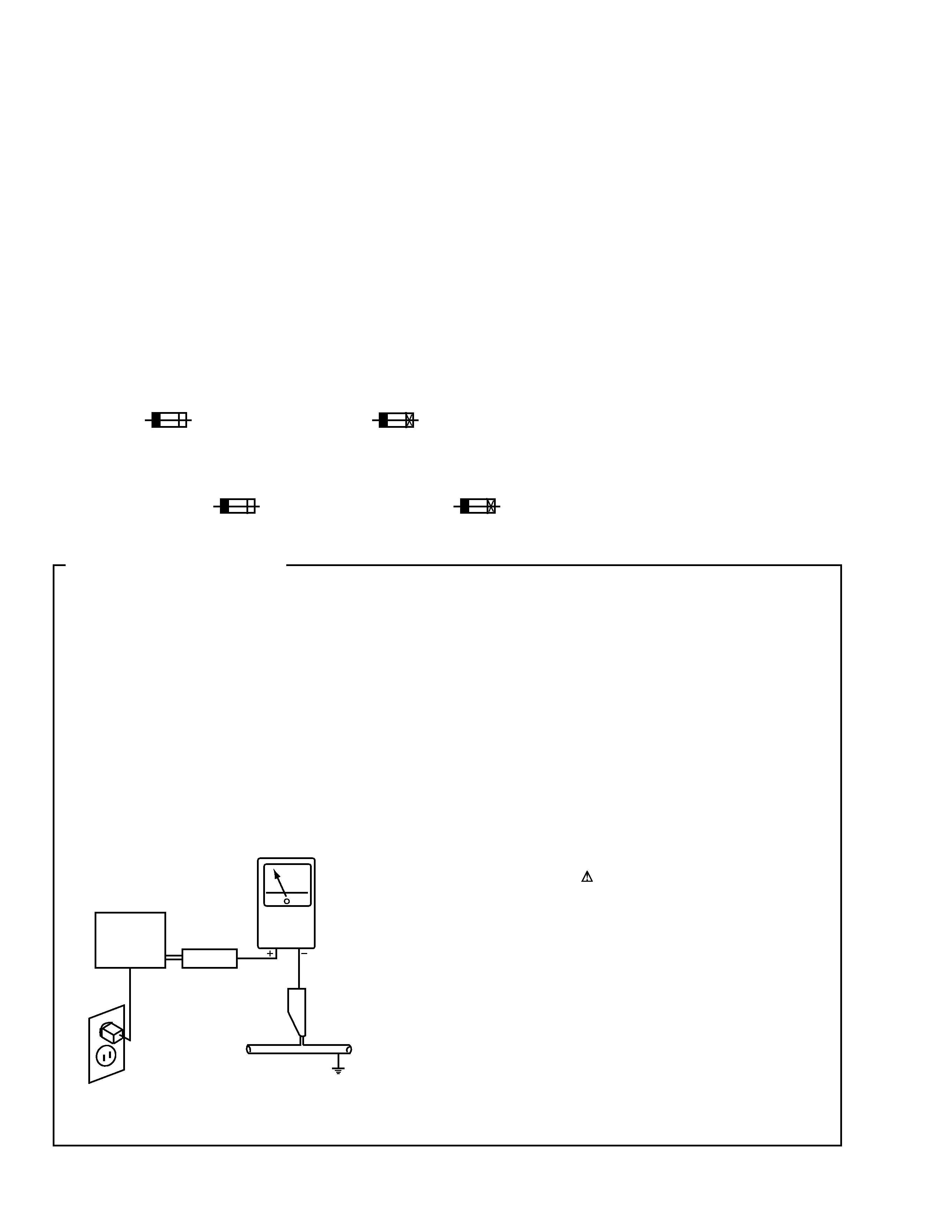
1. SAFETY PRECAUTIONS
The following check should be performed for the
continued protection of the customer and service
technician.
LEAKAGE CURRENT CHECK
Measure leakage current to a known earth ground (water
pipe, conduit, etc.) by connecting a leakage current tester
such as Simpson Model 229-2 or equivalent between the
earth ground and all exposed metal parts of the appliance
(input/output terminals, screwheads, metal overlays, control
shaft, etc.). Plug the AC line cord of the appliance directly
into a 120V AC 60Hz outlet and turn the AC power switch
on. Any current measured must not exceed 0.5mA.
(FOR USA MODEL ONLY)
Leakage
current
tester
Reading should
not be above
0.5mA
Device
under
test
Test all
exposed metal
surfaces
Also test with
plug reversed
(Using AC adapter
plug as required)
Earth
ground
AC Leakage Test
3
BD-V1100, BD-V1110
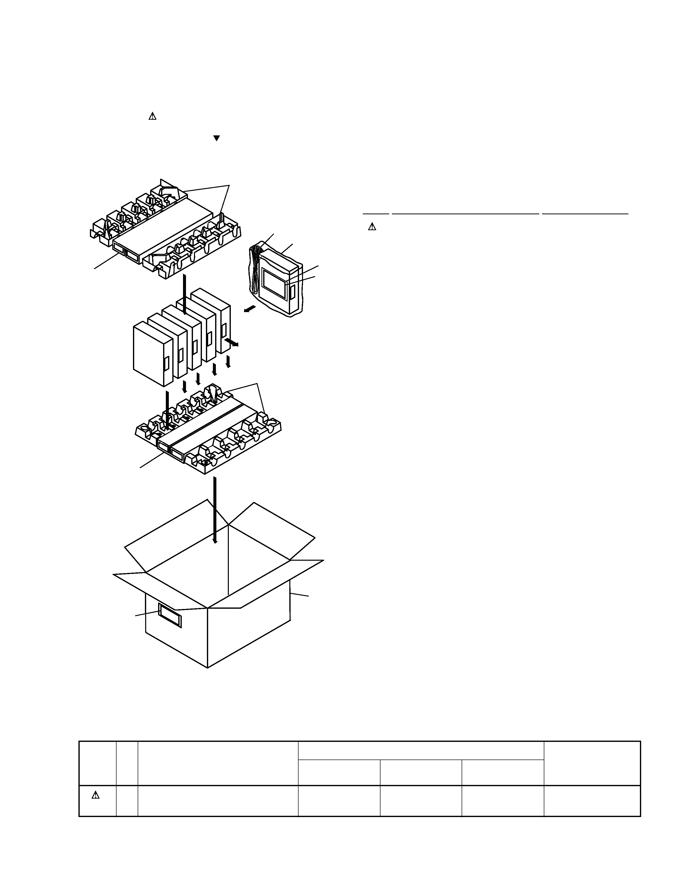
2.1 PACKING
1
AC Power Cord
See Contrast table(2)
2
Packing Case
See Contrast table(2)
3
Pulp Mold
BHX1021
4
Packing Sheet
BHG1063
5
Packing Spacer
BHA1150
6
Operating Instructions
BRB1057
(English)
NSP
7
Literature Bag
AHG-117
NSP
8
Bar-code Label
BAL1332
(1) PACKING PARTS LIST
Mark No.
Description
Part No.
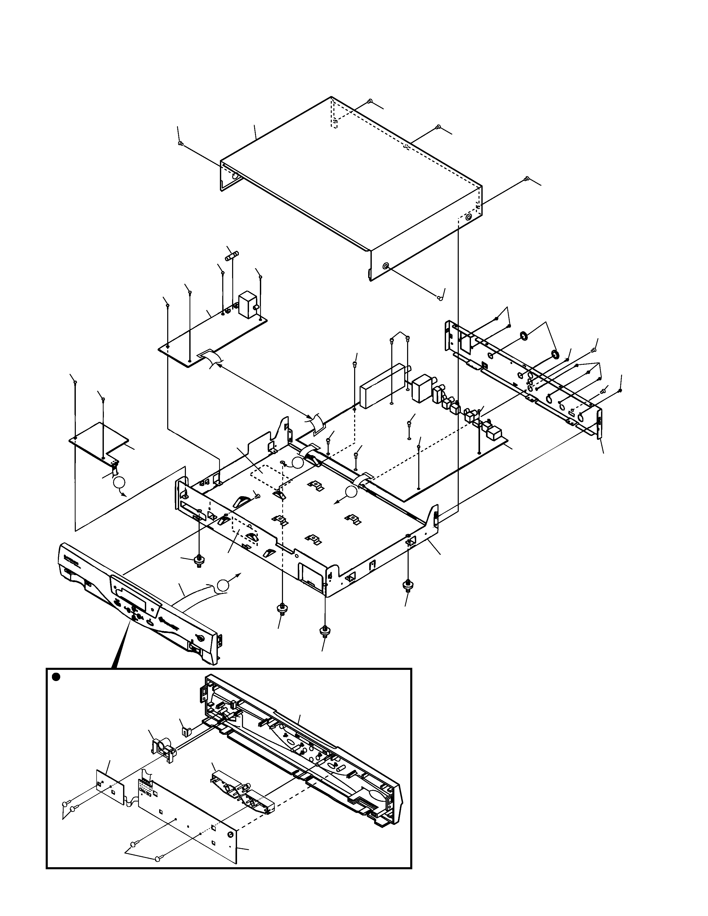
2. EXPLODED VIEWS AND PARTS LIST
NOTES:
· Parts marked by "NSP" are generally unavailable because they are not in our Master Spare Parts List.
· The mark found on some component parts indicates the importance of the safety factor of the part.
Therefore, when replacing, be sure to use parts of identical designation.
· Screws adjacent to mark on the product are used for disassembly.
FRONT
3
3
4
1
5
6
7
2
8
TOP
Front Side
5
Part No.
Remarks
Mark
BD-V1100
BD-V1100
BD-V1110
(2) CONTRAST TABLE
BD-V1100/KUXJ/1, /KU/1 and BD-V1110/KUXJ are constructed the same except for the following:
1
AC Power Cord
ADG7022
ADG7021
ADG7022
2
Packing Case
BHD1481
BHD1483
BHD1482
No.
Symbol and Description
/KUXJ/1
/KU/1
/KUXJ
4
BD-V1100, BD-V1110
2.2 EXTERIOR
27
27
27
27
32
27
26
30
30
30
30
31
13
28
2
29
29
29
29
3
29
29
7
29
29
29
29
6
9
14
21
20
14
8
C
C
B
B
14
22
23
Rear View
25
14
12
24
4
5
32
32
30
29
29
29
5
BD-V1100, BD-V1110
1
· · · · · · · · · · · · ·
2
MAIN Assy
BWX1141
3
SWITCHING POWER
BXF1136
SUPPLY Assy
4
FRONT PANEL Assy (PCB)
See Contrast table(2)
5
POWER SWITCH Assy
See Contrast table(2)
6
CARD Assy
See Contrast table(2)
7
FUSE (F1101 : 4A)
BEK1010
8
10P FFC (J9001)
BDD1040
(CARD CN4202
MAIN CN1203)
9
20P FFC (J9002)
BDD1041
(FRONT PANEL CN4103
MAIN CN2102)
10
· · · · · · · · · · · · ·
11
· · · · · · · · · · · · ·
12
Chassis
BNA1155
13
Rear Panel
See Contrast table(2)
14
Leg Assy
BEC1015
15
· · · · · · · · · · · · ·
16
· · · · · · · · · · · · ·
17
· · · · · · · · · · · · ·
18
· · · · · · · · · · · · ·
19
· · · · · · · · · · · · ·
20
Proposition 65 Label
BAX1249
21
UPC Label
See Contrast table(2)
22
Front Panel Assy
See Contrast table(2)
23
Indicator Lens
BAK1139
24
STATION Knob
BAD1119
25
POWER SW Knob
BAD1120
26
Bonnet
BNE1115
27
Screw
BBA1062
28
Nut
BBN1005
29
Screw
BBZ30P060FMC
30
Screw
BBZ30P080FZK
31
Screw
BMZ20P040FZK
32
Screw
BPZ26P080FMC
(1) EXTERIOR PARTS LIST
Mark No.
Description
Part No.
Part No.
Remarks
Mark
BD-V1100
BD-V1100
BD-V1110
(2) CONTRAST TABLE
BD-V1100/KUXJ/1, /KU/1 and BD-V1110/KUXJ are constructed the same except for the following:
4
FRONT PANEL ASSY
BWZ1905
BWZ1910
BWZ1905
5
POWER SWITCH ASSY
BWZ1906
BWZ1911
BWZ1906
6
CARD ASSY
BWZ1907
BWZ1912
BWZ1907
13
Rear Panel
BNC1164
BNC1164
BNC1165
21
UPC Label
BAX1277
BAX1278
BAX1279
22
Front Panel Assy
BMB1116
BMB1116
BMB1117
NSP
Name Label
Not used
BAL1399
Not used
No.
Symbol and Description
/KUXJ/1
/KU/1
/KUXJ