ORDER NO.
PIONEER CORPORATION 4-1, Meguro 1-chome, Meguro-ku, Tokyo 153-8654, Japan
PIONEER ELECTRONICS (USA) INC. P.O. Box 1760, Long Beach, CA 90801-1760, U.S.A.
PIONEER EUROPE NV Haven 1087, Keetberglaan 1, 9120 Melsele, Belgium
PIONEER ELECTRONICS ASIACENTRE PTE. LTD. 253 Alexandra Road, #04-01, Singapore 159936
PIONEER CORPORATION 2004
AVX-P7650TV/ES
CRT3236
7.0 INCH WIDE AV SYSTEM DISPLAY
AVX-P7650TV
/ES
For details, refer to "Important symbols for good services".
K-ZZU.JULY 2004 printed in Japan
AVX-P7650TV/ES
2
12
34
12
3
4
C
D
F
A
B
E
SAFETY INFORMATION
CAUTION
Danger of explosion if battery is incorrectly replaced.
Replaced only with the same or equivalent type.
Battery
Slide the tray out on the back of the
remote controller and insert the battery
with the (+) and () poles pointing in
the proper direction.
Note :
· Use a CR2025 (3V) lithium battery
only. Never use other types of battery
with this unit.
- Inverter for LCD back light becomes a high voltage.
NOTE:
- Service Precaution
1. You should conform to the regulations governing the product
(safety, radio and noise, and other regulations), and should keep
the safety during servicing by following the safety instructions
described in this manual.
This service manual is intended for qualified service technicians; it is not meant for the casual do-it-yourselfer.
Qualified technicians have the necessary test equipment and tools, and have been trained to properly and safely
complex products such as those covered by this manual.
Improperly performed repairs can adversely affect the safety and reliability of the product and may void the
If you are not qualified to perform the repair of this product properly and safely, you should not risk
and refer the repair to a qualified service technician.
repair
warranty.
trying to do so
AVX-P7650TV/ES
3
56
7
8
56
7
8
C
D
F
A
B
E
[ Important symbols for good services ]
In this manual, the symbols shown-below indicate that adjustments, settings or cleaning should be made securely.
When you find the procedures bearing any of the symbols, be sure to fulfill them:
2. Adjustments
To keep the original performances of the product, optimum adjustments or specification confirmation is indispensable.
In accordance with the procedures or instructions described in this manual, adjustments should be performed.
3. Cleaning
For optical pickups, tape-deck heads, lenses and mirrors used in projection monitors, and other parts requiring cleaning,
proper cleaning should be performed to restore their performances.
5. Lubricants, glues, and replacement parts
Appropriately applying grease or glue can maintain the product performances. But improper lubrication or applying
glue may lead to failures or troubles in the product. By following the instructions in this manual, be sure to apply the
prescribed grease or glue to proper portions by the appropriate amount.For replacement parts or tools, the prescribed
ones should be used.
4. Shipping mode and shipping screws
To protect the product from damages or failures that may be caused during transit, the shipping mode should be set or
the shipping screws should be installed before shipping out in accordance with this manual, if necessary.
1. Product safety
You should conform to the regulations governing the product (safety, radio and noise, and other regulations), and
should keep the safety during servicing by following the safety instructions described in this manual.

AVX-P7650TV/ES
4
12
34
12
3
4
C
D
F
A
B
E
CONTENTS
SAFETY INFORMATION ..................................................................................................................................... 2
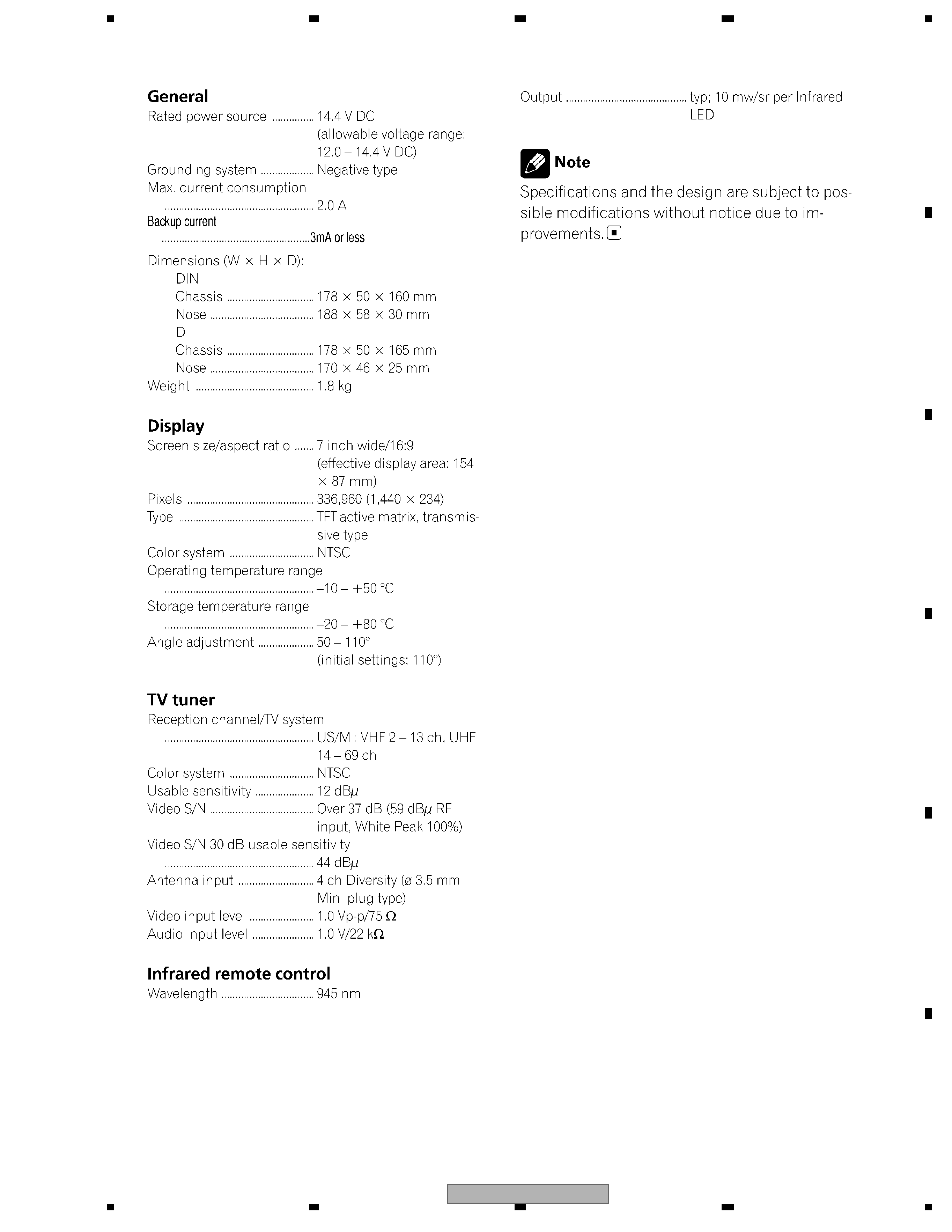
1. SPECIFICATIONS ............................................................................................................................................ 5
2. EXPLODED VIEWS AND PARTS LIST ............................................................................................................ 6
2.1 PACKING ................................................................................................................................................... 6
2.2 EXTERIOR(1) ............................................................................................................................................ 8
2.3 EXTERIOR(2) .......................................................................................................................................... 10
2.4 EXTERIOR(3) .......................................................................................................................................... 12
3. BLOCK DIAGRAM AND SCHEMATIC DIAGRAM ..........................................................................................14
3.1 BLOCK DIAGRAM ................................................................................................................................... 14
3.2 OVERALL CONNECTION DIAGRAM...................................................................................................... 16
3.3 MOTHER UNIT(MAIN)(GUIDE PAGE)..................................................................................................... 18
3.4 MOTHER UNIT(TV TUNER) .................................................................................................................... 24
3.5 KEYBOARD UNIT.................................................................................................................................... 26
3.6 MONITOR UNIT(GUIDE PAGE)............................................................................................................... 28
3.7 INVERTER PCB....................................................................................................................................... 34
3.8 MAIN UNIT, SW UNIT AND VOLUME UNIT ............................................................................................ 36
4. PCB CONNECTION DIAGRAM ..................................................................................................................... 38
4.1 MOTHER UNIT ........................................................................................................................................ 38
4.2 KEYBOARD UNIT.................................................................................................................................... 42
4.3 MONITOR PCB ........................................................................................................................................ 44
4.4 INVERTER PCB....................................................................................................................................... 48
4.5 UPPER PCB ............................................................................................................................................ 49
4.6 MAIN UNIT............................................................................................................................................... 50
4.7 SW UNIT AND VOLUME UNIT ................................................................................................................ 52
5. ELECTRICAL PARTS LIST ............................................................................................................................ 53
6. ADJUSTMENT ............................................................................................................................................... 67
6.1 JIG CONNECTION DIAGRAM................................................................................................................. 67
6.2 MOTHER PCB ADJUSTMENT ................................................................................................................ 68
6.3 MONITOR PCB ADJUSTMENT............................................................................................................... 71
6.4 INVERTER PCB ADJUSTMENT ............................................................................................................. 75
6.5 MONITOR TEST MODE .......................................................................................................................... 76
6.6 FREQUENCY CHECK FOR CLOCK ....................................................................................................... 81
7. GENERAL INFORMATION ............................................................................................................................. 82
7.1 DIAGNOSIS ............................................................................................................................................. 82
7.1.1 DISASSEMBLY ..................................................................................................................................... 82
7.1.2 CONNECTOR FUNCTION DESCRIPTION .......................................................................................... 87
7.2 IC ............................................................................................................................................................. 88
7.3 SYSTEM BLOCK DIAGRAM ................................................................................................................... 97
7.3.1 MECHANISM DESCRIPTIONS ............................................................................................................ 97
7.3.2 OPERATIONAL FLOW CHART .......................................................................................................... 103
8. OPERATIONS .............................................................................................................................................. 104
AVX-P7650TV/ES
5
56
7
8
56
7
8
C
D
F
A
B
E
1. SPECIFICATIONS