ORDER NO.
PIONEER CORPORATION 4-1, Meguro 1-chome, Meguro-ku, Tokyo 153-8654, Japan
PIONEER ELECTRONICS (USA) INC. P.O. Box 1760, Long Beach, CA 90801-1760, U.S.A.
PIONEER EUROPE NV Haven 1087, Keetberglaan 1, 9120 Melsele, Belgium
PIONEER ELECTRONICS ASIACENTRE PTE. LTD. 253 Alexandra Road, #04-01, Singapore 159936
PIONEER CORPORATION 2002
ANH-P9R/EW
CRT2877
NAVIGATION/CD TUNER
ANH-P9R
/EW
This service manual should be used together with the following manual(s):
Model No.
Order No.
Mech.Module
Remarks
CX-977
CRT2624
S9
CD Mech. module:Circuit Description, Mech.Description, Disassembly
For details, refer to "Important symbols for good services".
K-ZZS.JUNE 2002.printed in Japan
ANH-P9R/EW
A
B
C
D
12
34
12
3
4
2
SAFETY INFORMATION
This service manual is intended for qualified service technicians; it is not meant for the casual do-it-yourselfer.
Qualified technicians have the necessary test equipment and tools, and have been trained to properly and safely repair
complex products such as those covered by this manual.
Improperly performed repairs can adversely affect the safety and reliability of the product and may void the warranty.
If you are not qualified to perform the repair of this product properly and safely, you should not risk trying to do so
and refer the repair to a qualified service technician.
1. Safety Precautions for those who Service this Unit.
· When checking or adjusting the emitting power of the laser diode exercise caution in order to get safe, reliable
results.
Caution:
1. During repair or tests, minimum distance of 13cm from the focus lens must be kept.
2. During repair or tests, do not view laser beam for 10 seconds or longer.
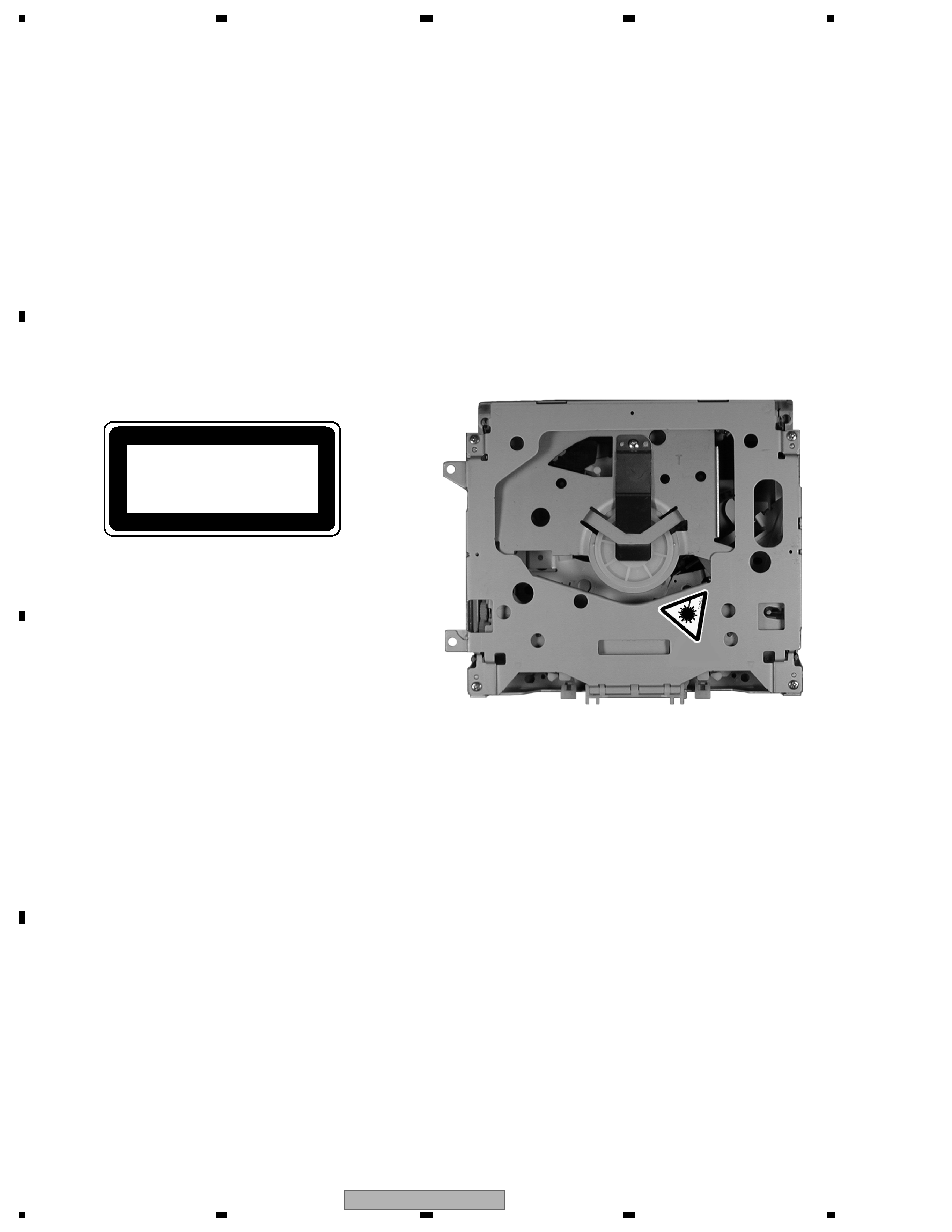
2. A "CLASS 1 LASER PRODUCT" label is affixed to the
bottom of the player.
3. The triangular label is attached to the mechanism
unit frame.
4. Specifications of Laser Diode
Specifications of laser radiation fields to which human access is possible during service.
Wavelength
=
800 nanometers
CLASS 1
LASER PRODUCT
ANH-P9R/EW
A
B
C
D
56
7
8
56
7
8
3
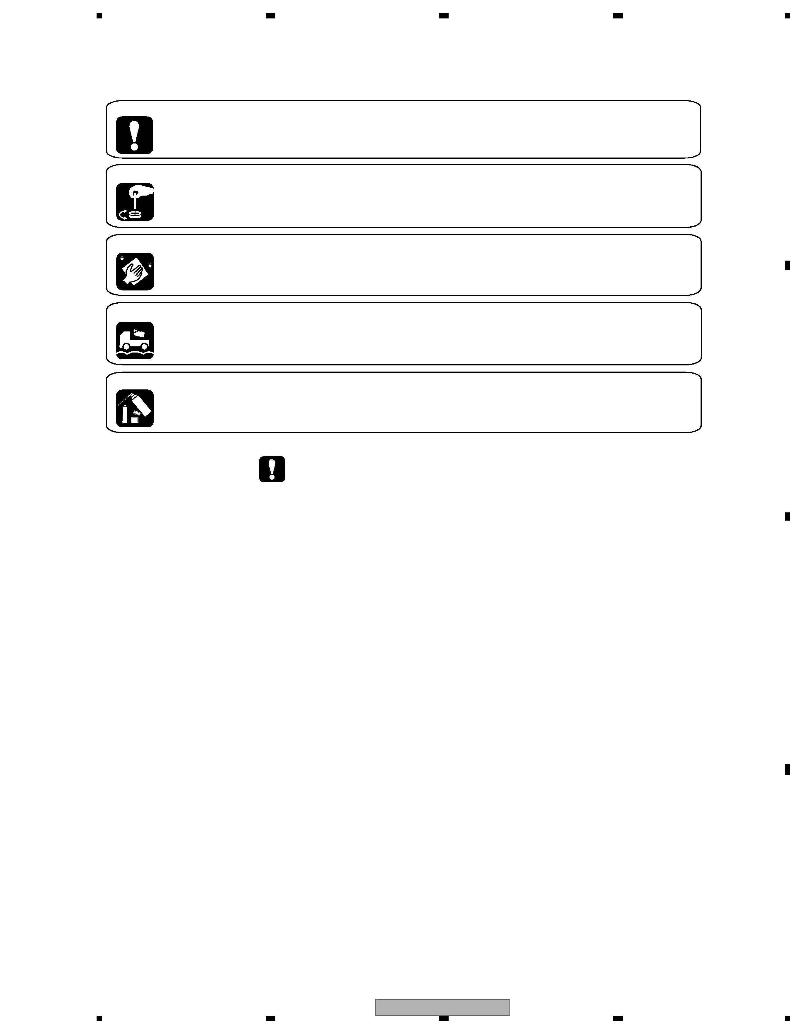
[ Important symbols for good services ]
In this manual, the symbols shown-below indicate that adjustments, settings or cleaning should be made securely.
When you find the procedures bearing any of the symbols, be sure to fulfill them:
2. Adjustments
To keep the original performances of the product, optimum adjustments or specification confirmation is indispensable.
In accordance with the procedures or instructions described in this manual, adjustments should be performed.
3. Cleaning
For optical pickups, tape-deck heads, lenses and mirrors used in projection monitors, and other parts requiring cleaning,
proper cleaning should be performed to restore their performances.
5. Lubricants, glues, and replacement parts
Appropriately applying grease or glue can maintain the product performances. But improper lubrication or applying
glue may lead to failures or troubles in the product. By following the instructions in this manual, be sure to apply the
prescribed grease or glue to proper portions by the appropriate amount.For replacement parts or tools, the prescribed
ones should be used.
4. Shipping mode and shipping screws
To protect the product from damages or failures that may be caused during transit, the shipping mode should be set or
the shipping screws should be installed before shipping out in accordance with this manual, if necessary.
1. Product safety
You should conform to the regulations governing the product (safety, radio and noise, and other regulations), and
should keep the safety during servicing by following the safety instructions described in this manual.
- CD section precaution
1. Before disassembling the unit, be sure to turn off the
power. Unplugging and plugging the connectors dur-
ing power-on mode may damage the ICs inside the
unit.
2. To protect the pickup unit from electrostatic dis-
charge during servicing, take an appropriate treat-
ment (shorting-solder) by referring to "the DISAS-
SEMBLY" on page 56.
3. After replacing the pickup unit, be sure to check the
grating. (See p.51.)

ANH-P9R/EW
A
B
C
D
12
34
12
3
4
4
CONTENTS
SAFETY INFORMATION . . . . . . . . . . . . . . . . . . . . . . . . . . . . . . . . . . . . . . . . . . . . . . . . .2
1. SPECIFICATIONS . . . . . . . . . . . . . . . . . . . . . . . . . . . . . . . . . . . . . . . . . . . . . . . . . . .5
2. EXPLODED VIEWS AND PARTS LIST . . . . . . . . . . . . . . . . . . . . . . . . . . . . . . . . . . . . . . . .6
2.1 PACKING . . . . . . . . . . . . . . . . . . . . . . . . . . . . . . . . . . . . . . . . . . . . . . . . . . . . .6
2.2 EXTERIOR. . . . . . . . . . . . . . . . . . . . . . . . . . . . . . . . . . . . . . . . . . . . . . . . . . . . .8
2.3 CD MECHANISM MODULE (S9ARROW) . . . . . . . . . . . . . . . . . . . . . . . . . . . . . . . . . . . . 10
3. BLOCK DIAGRAM AND SCHEMATIC DIAGRAM . . . . . . . . . . . . . . . . . . . . . . . . . . . . . . . . . . 12
3.1 BLOCK DIAGRAM . . . . . . . . . . . . . . . . . . . . . . . . . . . . . . . . . . . . . . . . . . . . . . . . 12
3.2 OVERALL CONNECTION DIAGRAM . . . . . . . . . . . . . . . . . . . . . . . . . . . . . . . . . . . . . . 14
3.3 MAIN UNIT(GUIDE PAGE) . . . . . . . . . . . . . . . . . . . . . . . . . . . . . . . . . . . . . . . . . . . 16
3.4 KEYBOARD UNIT . . . . . . . . . . . . . . . . . . . . . . . . . . . . . . . . . . . . . . . . . . . . . . . . 22
3.5 PANEL UNIT . . . . . . . . . . . . . . . . . . . . . . . . . . . . . . . . . . . . . . . . . . . . . . . . . . . 24
3.6 CD MECHANISM MODULE . . . . . . . . . . . . . . . . . . . . . . . . . . . . . . . . . . . . . . . . . . . 26
4. PCB CONNECTION DIAGRAM . . . . . . . . . . . . . . . . . . . . . . . . . . . . . . . . . . . . . . . . . . . 30
4.1 MAIN UNIT. . . . . . . . . . . . . . . . . . . . . . . . . . . . . . . . . . . . . . . . . . . . . . . . . . . . 30
4.2 KEYBOARD UNIT . . . . . . . . . . . . . . . . . . . . . . . . . . . . . . . . . . . . . . . . . . . . . . . . 34
4.3 PANEL UNIT . . . . . . . . . . . . . . . . . . . . . . . . . . . . . . . . . . . . . . . . . . . . . . . . . . . 35
4.4 CD MECHANISM MODULE . . . . . . . . . . . . . . . . . . . . . . . . . . . . . . . . . . . . . . . . . . . 36
5. ELECTRICAL PARTS LIST . . . . . . . . . . . . . . . . . . . . . . . . . . . . . . . . . . . . . . . . . . . . . 38
6. ADJUSTMENT . . . . . . . . . . . . . . . . . . . . . . . . . . . . . . . . . . . . . . . . . . . . . . . . . . . . 47
6.1 TEST MODE . . . . . . . . . . . . . . . . . . . . . . . . . . . . . . . . . . . . . . . . . . . . . . . . . . . 47
6.2 SERVICE GARAGE MODE . . . . . . . . . . . . . . . . . . . . . . . . . . . . . . . . . . . . . . . . . . . 48
6.3 CD ADJUSTMENT. . . . . . . . . . . . . . . . . . . . . . . . . . . . . . . . . . . . . . . . . . . . . . . . 49
6.4 CHECKING THE GRATING AFTER CHANGING THE PICKUP UNIT . . . . . . . . . . . . . . . . . . . . . 51
6.5 ERROR CODE(CD) . . . . . . . . . . . . . . . . . . . . . . . . . . . . . . . . . . . . . . . . . . . . . . . 53
7. GENERAL INFORMATION . . . . . . . . . . . . . . . . . . . . . . . . . . . . . . . . . . . . . . . . . . . . . . 56
7.1 DIAGNOSIS . . . . . . . . . . . . . . . . . . . . . . . . . . . . . . . . . . . . . . . . . . . . . . . . . . . 56
7.1.1 DISASSEMBLY . . . . . . . . . . . . . . . . . . . . . . . . . . . . . . . . . . . . . . . . . . . . . . . . 56
7.1.2 CONNECTOR FUNCTION DESCRIPTION . . . . . . . . . . . . . . . . . . . . . . . . . . . . . . . . . . 60
7.2 IC . . . . . . . . . . . . . . . . . . . . . . . . . . . . . . . . . . . . . . . . . . . . . . . . . . . . . . . . 61
7.3 OPERATIONAL FLOW CHART . . . . . . . . . . . . . . . . . . . . . . . . . . . . . . . . . . . . . . . . . 71
7.4 CLEANING. . . . . . . . . . . . . . . . . . . . . . . . . . . . . . . . . . . . . . . . . . . . . . . . . . . . 72
8. OPERATIONS . . . . . . . . . . . . . . . . . . . . . . . . . . . . . . . . . . . . . . . . . . . . . . . . . . . . 73

ANH-P9R/EW
A
B
C
D
56
7
8
56
7
8
5
1. SPECIFICATIONS
General
Power source .................. 14.4 V DC
(10.8 15.1 V allowable)
Grounding system .......... Negative type
Max. current consumption
......................................... 10.0 A
Backup current
.........................................Less than 6 mA
Dimensions (W x H x D):
Chassis (DIN) ........... 178 x 50 x 157 mm
Nose ......................... 188 x 58 x 18.0 mm
Weight ............................. 2.0 kg
Navigation
(GPS receiver)
System ............................. L1, C/Acode GPS
SPS (Standard Positioning
Service)
Reception system ........... 12ch
Reception frequency ...... 1,575.42 MHz
Sensitivity ....................... 130 dbm
Position update frequency
Approx. once per second
(Common)
Maximum current consumption
......................................... 10 A
Power source ......................... DC 14.4 V (10.815.1 V allowed)
Ground type ........................... Negative type
(GPS antenna)
Aerial ............................... Micro strip flat
antena/right-handed
helical polarizaton
Aerial cable ..................... 5.0 m
(Dimensions)
Main unit ............................... 178 (W) x 50 (H) x 157 (D) mm
GPS antenna .................... 46 (W) x 46 (H) x 13 (D) mm
(Weight)
Main unit .......................... 1.5 kg
GPS aerial ......................... 115 g
Audio
Maximum power output 50 W x 4
50 W x 2 ch/4
+ 70 W x 1 ch/2
(for subwoofer)
Continuous power output
27 W x 4
(DIN 45324, +B=14.4 V)
Load impedance ............. 4
(4 8 [2 for 1 ch]
allowable)
Preout max output level/output impedance
......................................... 2.2 V/1 k
Equalizer (3-Band Parametric Equalizer):
(Low)
Frequency ......... 40/80/100/160 Hz
Q Factor ............. 0.35/0.59/0.95/1.15
(+6 dB when boosted)
Gain ...................
±12 dB
(Mid)
Frequency ......... 200/500/1 k/2 k Hz
Q Factor ............. 0.35/0.59/0.95/1.15
(+6 dB when boosted)
Gain ...................
±12 dB
(High)
Frequency ......... 3.15 k/8 k/10 k/12.5 k Hz
Q Factor ............. 0.35/0.59/0.95/1.15
(+6 dB when boosted)
Gain ...................
±12 dB
Loudness contour:
(Low) ........................ +3.5 dB (100 Hz)
+3 dB (10 kHz)
(Mid) ......................... +10 dB (100 Hz)
+6.5 dB (10 kHz)
(High) ....................... +11 dB (100 Hz)
+11 dB (10 kHz)
(Volume: 30 dB)
Tone controls:
(Bass)
Frequency ......... 40/63/100/160 Hz
Gain ...................
±12 dB
(Treble)
Frequency ......... 2.5 k/4 k/6.3 k/10 k Hz
Gain ...................
±12 dB
Subwoofer:
Frequency ......... 50/80/125 Hz
Slope ................. 12 dB/oct
Gain ...................
±12 dB
CD player
System ............................ Compact disc audio
system
Usable discs .................... Compact disc
Signal format:
Sampling frequency 44.1 kHz
Number of quantization bits
.................................. 16; linear
Frequency characteristics
......................................... 5 20,000 Hz (
±1 dB)
Signal-to-noise ratio ....... 94 dB (1 kHz)
(IEC-A network)
Dynamic range ................ 92 dB (1 kHz)
Number of channels ....... 2 (stereo)
FM tuner
Frequency range ............. 87.5 108.0 MHz
Usable sensitivity ........... 9 dBf (0.8
µV/75 , mono,
S/N: 30 dB)
50 dB quieting sensitivity
15 dBf (1.5
µV/75 , mono)
Signal-to-noise ratio ....... 70 dB (IEC-A network)
Distortion ........................ 0.3% (at 65 dBf, 1 kHz,
stereo)
Frequency response ....... 30 15,000 Hz (
±3 dB)
Stereo separation ........... 40 dB (at 65 dBf, 1 kHz)
MW tuner
Frequency range ............. 531 1,602 kHz (9 kHz)
Usable sensitivity ........... 18
µV (S/N: 20 dB)
Selectivity ....................... 50 dB (
±9 kHz)
LW tuner
Frequency range ............. 153 281 kHz
Usable sensitivity ........... 30
µV (S/N: 20 dB)
Selectivity ....................... 50 dB (
±9 kHz)