A-307R
Operating Instructions
Manual de instrucciones
STEREO AMPLIFIER
AMPLIFICADOR ESTEREOFONICO
2
Mains voltages in Saudi Arabia are 127 V and
220 V only. Never use this model with the 110
V setting in Saudi Arabia.
H019 En
LINE VOLTAGE SELECTOR SWITCH H038 En
The line voltage selector switch is located on the rear panel.
Check that it is set properly before plugging the power cord
into the outlet. If the voltage is not properly set or if you move
to an area where the voltage requirements differ, adjust the
selector switch as follows:
¶ Be sure to disconnect the power cord from its outlet before
making this adjustment.
¶ Use a medium-sized (flat blade) screwdriver. Insert the tip
of the screwdriver into the groove of the selector switch
and turn it so that the power voltage marking of your area
points to the arrow.
CAUTION 220 V
Power source voltage is factory adjusted 220 volts. If your area
is different, change voltage selectors settings.
H038 En
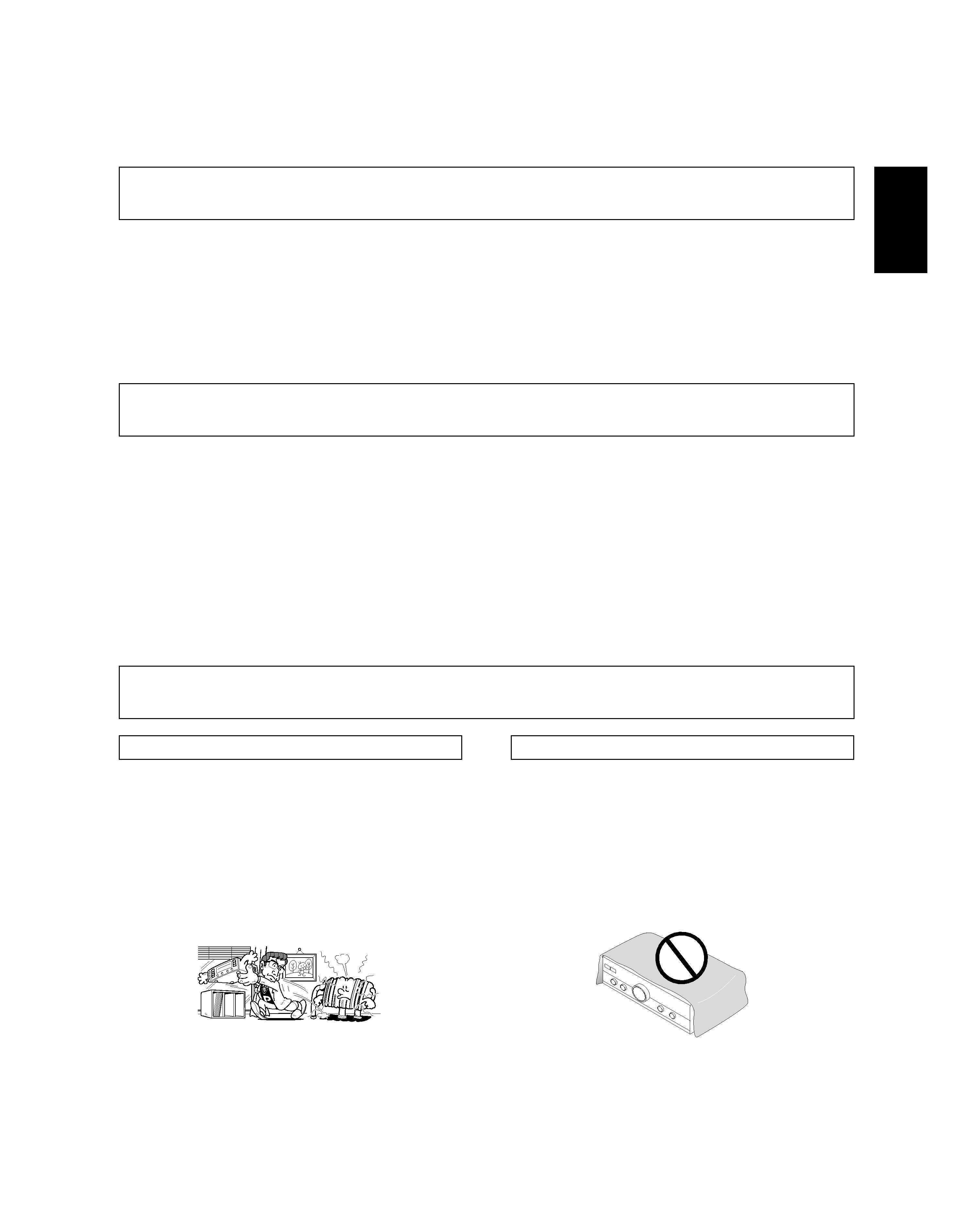
Operating Environment H045 En
Operating environment temperature and humidity:
+5°C +35°C (+41°F +95°F); less than 85%RH (cooling vents
not blocked)
Do not install in the following locations
÷ Location exposed to direct sunlight or strong artificial light
÷ Location exposed to high humidity, or poorly ventilated
location
220V
110V
120-127V
240V
3
English
When installing this unit, make sure to leave space around the
unit for ventilation to improve heat radiation (at least 60 cm at
top, 10 cm at rear, and 30 cm at each side).
WARNING: Slot and openings in the cabinet are provided for
ventilation and to ensure reliable operation of the product and
to protect it from overheating, to prevent fire hazard, the openings
should never be blocked and covered with items, such as
newspapers, table-cloths, curtains, etc. Also do not put the
apparatus on the thick carpet, bed, sofa, or fabric having a thick
pile.
H040En
CONTENTS
FEATURES
7 Direct Energy MOS Power Amp
Pioneer introduces amp circuitry featuring HEX power
MOS FET devices for high performance. Together with
Pioneer's original Wide Range Linear Circuit technology,
this helps achieve reducing power consumption, while
maintaining the power of current models.
In terms of performance, it contributes to flat damping
factor characteristics across the audio spectrum, and im-
proved power linearity.
7 Low power consumption design
7 High-power Output........ 80 W + 80 W/4 (DIN)
55 W + 55 W/8
(DIN)
7 Wide-Range Linear Circuit
This new current feedback circuit assures improved
operating stability for flat output impedance and stable
driving of speakers across the full range of frequencies.
7 Silent microprocessor system
INSTALLATION
LOCATION
Install the unit in a well ventilated location where it
will not be exposed to high temperature or humidity.
Do not install the unit in a location which is exposed to direct
rays of the sun, or near hot appliances or radiators. Excessive
heat can adversely affect the cabinet and internal components.
Installation of the unit in a damp or dusty environment may
also result in a malfunction or an accident. (Avoid installation
near cookers etc., where the unit may be exposed to oily
smoke, steam or heat.)
Do not install the unit on a tottered stand, nor on an unstable
or inclined surface.
VENTILATION
FEATURES ......................................................................... 3
INSTALLATION .................................................................. 3
CONNECTIONS ................................................................. 4
PANEL FACILITIES ............................................................ 7
OPERATIONS .................................................................. 10
REMOTE CONTROL ........................................................ 11
TROUBLESHOOTING ...................................................... 13
SPECIFICATIONS ............................................................. 14
Thank you for buying this PIONEER product.
Please read through these operating instructions so you will know how to operate your model properly. After you have finished
reading the instructions, put them away in a safe place for future reference.
4
SPEAKERS
RL
R
A
B
L
ª·
·
ª
SIGNAL
GND
L
R
PHONO
IN
TUNER
IN
CD
IN
LINE
IN
TAPE 1/MD
REC
PLAY
REC
PLAY
TAPE 2 MONITOR
OUT
IN
OUT
IN
L
R
AC INLET
REC
PLAY
L
R
REC
PLAY
L
R
CD
OUT
L
R
IN
OUT
L
R
FM-AM
OUT
L
R
L
R
L
R
ª
·
ª
·
L
L
R
R
L
R
L
R
L
R
L
R
ª
·
ª
L
AUDIO OUT
L
R
L
R
L
R
L
R
MINIDISC
CONTROL
OUT
R
L
R
L
R
L
·
L
R
L
L
R
R
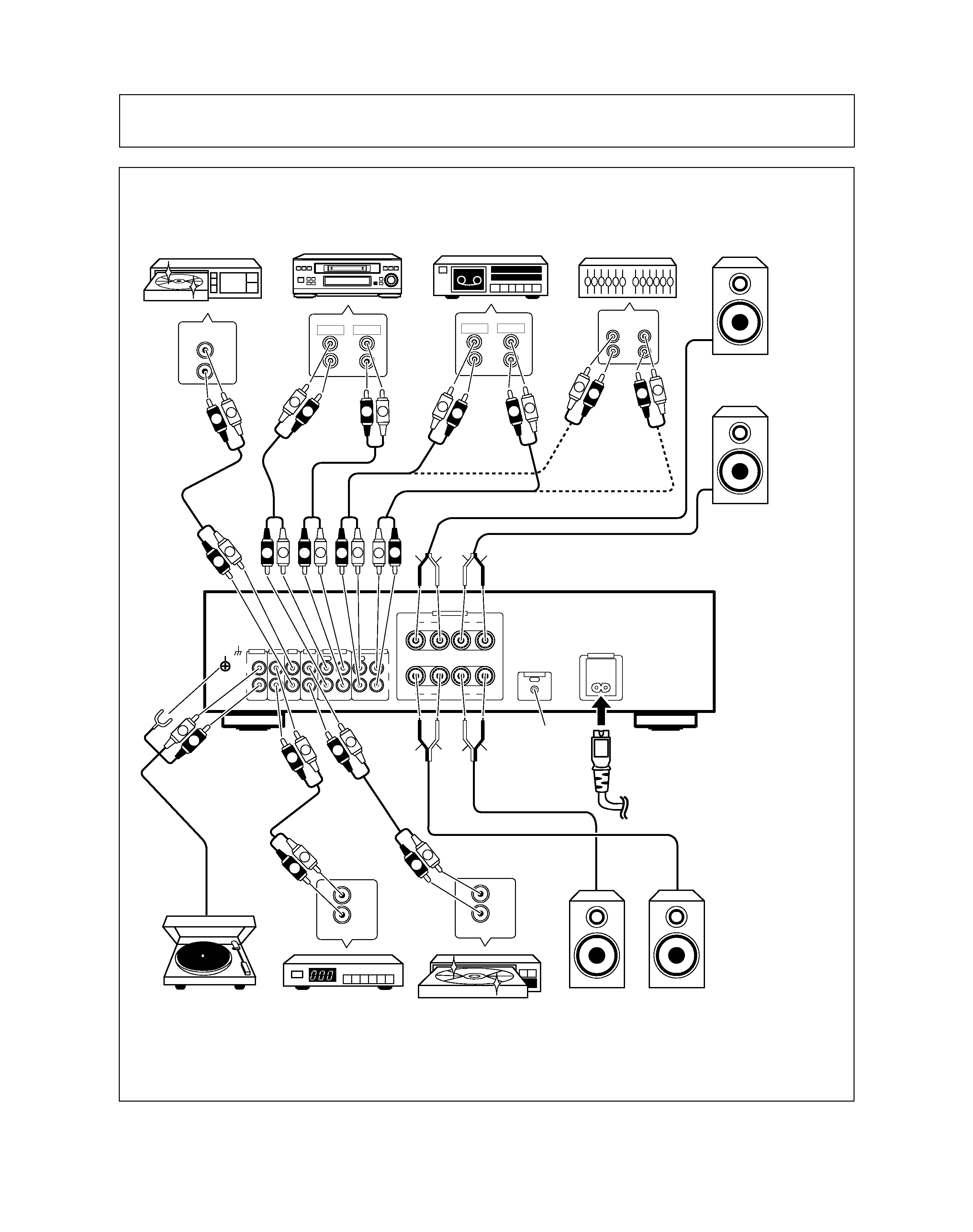
CONNECTIONS
To an AC wall socket.
See page 5.
Left (L)
Speaker system A
Right (R)
Turntable
Cassette deck/MD recorder
Tuner
LD player, VCR, etc.
Speaker system B
Adaptor component
(graphic equalizer, etc.)
Cassette deck
CD player
Right (R)
Left (L)
Before making or changing the connections, switch off the power and disconnect the power cord from the AC
outlet.
H029BEn
See page 6.
5
English
L
R
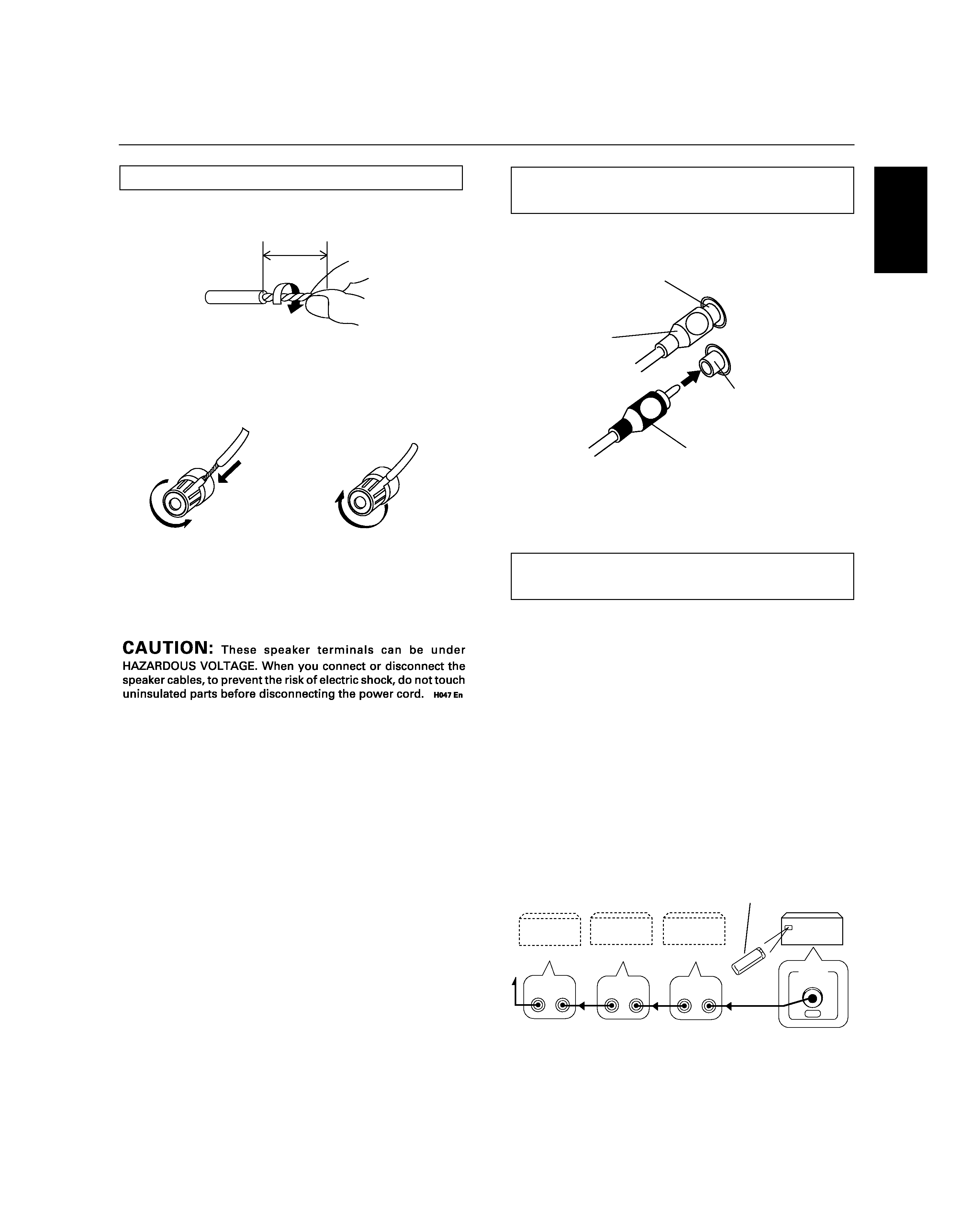
CONNECTIONS
CONNECTING THE SPEAKER CORDS
2. Loosen the knob and insert the wire core into the
terminal hole.
3. Tighten the knob to fix the wire core in place.
1. Strip off the vinyl covering and twist the tip of the
wire core.
10mm
Twist the wire core.
NOTE:
Do not allow any of the cord conductors to protrude from the
terminals or touch any other conductors. Malfunctioning or
breakdowns may occur when conductors come into contact
with each other.
Speaker Impedance
When speaker systems are connected to only SPEAKERS A
or SPEAKERS B terminals, such speakers should have rated
impedance in the range of 416
.
When speaker are connected to both A and B terminals, they
should have a rated impedance in the range of 8 32
.
\
CONNECTING THE INPUT/OUTPUT
CORDS
Connect the white plug to the L (left) channel, and the red plug
to the R (right) channel. Be sure to push the plugs securely.
Left channel
White plug
Right channel
Red plug
REMOTE CONTROL CORD
CONNECTIONS
By interconnecting the CONTROL jacks of Pioneer units with
the
Î mark, the entire system can be operated with this
remote control unit, although some of the units (AM/FM
tuner, CD player, cassette deck, etc.) may not be equipped
with remote sensors. The entire system can be operated by
a remote control unit by connecting PIONEER stereo
components to each other using the control input (CONTROL
IN) jack on each component. Use the remote control cord
supplied with the respective unit for the connection. An
example is shown in the figure. As long as you connect
"OUT" to "IN", the connecting sequence is arbitrary. When
a unit has only an "IN" connector, however, connect it last.
NOTE:
When the POWER switch is set to OFF, the components
connected to the CONTROL OUT jack can not be operated
with the remote control unit.
AM/FM
tuner
CD player
Cassette
deck
3
2
1
A-307R
Remote
control unit
CONTROL
OUT
CONTROL
OUT
IN
CONTROL
OUT
IN
CONTROL
OUT
IN