TX-SR804/804E
SERVICE MANUAL
SERVICE MANUAL
Ref. No. 3950
102006
120V AC, 60Hz
230-240V AC, 50Hz
120/220-240V AC, 50/60Hz
220-230V AC, 50Hz
TX-SR804 Black, Golden and Silver models
B MDC, S MDC
B MPA, S MPA
G MWT
G MGK, G MGR, G MGQ
TX-SR804E Black and Silver models
230-240V AC, 50Hz
B MPP, S MPP
AV RECEIVER
MODEL
TX-SR804E
SAFETY-RELATED COMPONENT
WARNING!!
COMPONENTS IDENTIFIED BY MARK
ON THE
SCHEMATIC DIAGRAM AND IN THE PARTS LIST ARE
CRITICAL FOR RISK OF FIRE AND ELECTRIC SHOCK.
REPLACE THESE COMPONENTS WITH ONKYO
PARTS WHOSE PART NUMBERS APPEAR AS SHOWN
IN THIS MANUAL.
MAKE LEAKAGE-CURRENT OR RESISTANCE
MEASUREMENTS TO DETERMINE THAT EXPOSED
PARTS ARE ACCEPTABLY INSULATED FROM THE
SUPPLY CIRCUIT BEFORE RETURNING THE
APPLIANCE TO THE CUSTOMER.
MODEL
TX-SR804
RC-620M
THX
10
--/---
11
12
REMOTE MODE
HDD
RECEIVER
TAPE/AMP
DVD
CD
ZONE2
SAT
TV
VCR
CABLE
MD
CDR
STEREO
SURR
DIRECT
SUBTITLE
AUDIO
ALLST
PLAY MODE
VIDEO OFF
REPEAT
RANDOM
REC
PLAYLIST
OPEN/CLOSE
Re-EQ
+
-
TV CH
TV VOL
ENTER
SET
UP
TO
P M
ENU
MEN
U
VOL
+
-
CH
DISPLAY
PREV
CH
DIMMER
SLEEP
MUTING
LISTENING MODE
INPUT SELECTOR
3
2
MACRO
1
+10
0
CLEAR
12
3
45
6
78
9
INPUT
I
ON
STANDBY
TV
CD
V1
V2
V3
MULTI CH
DVD
TUNER
PHONO
DISC
ALBUM
V4
TAPE
PURE A
TEST TONE
CH SEL
LEVEL
LEVEL
L NIGHT
RE
TURN
RC-620M
STANDBY/ON
STANDBY
MASTER VOLUME
PHONO
ZONE 2
DISPLAY
PURE AUDIO
TUNER
TAPE
VIDEO 4
VIDEO 3
VIDEO 2
VIDEO 1
DVD
MULTI CH
CD
OFF
ON
POWER
PUSH TO OPEN
TX-SR804
TX-SR804/804E
SERVICE PROCEDURE
1. Replacing the fuses
This symbol located near the fuse indicates that the
fuse used is show operating type, For continued protection against
fire hazard, replace with same type fuse, For fuse rating, refer to
the marking adjacent to the symbol.
Ce symbole indique que le fusible utilise est e lent.
Pour une protection permanente, n'utiliser que des fusibles de meme
type. Ce demier est indique la qu le present symbol est apposre.
2. To initialize the unit
This model uses a battery-less memory backup system in order to retain radio presets and other settings
when it's unplugged or in the case of a power failure.
Although no batteries are required, the unit must be plugged into an AC outlet in order to charge the
backup system. Once it has been charged, the unit will retain the settings for several weeks,
although this depends on the environment and will be shorter in humid climates.
1. Press and hold down VIDEO 1 button, then press STANDBY/ON button when the unit is Power on.
2. After " Clear " is displayed, the preset memory and each mode stored in the memory are initialized and will
return to the factory settings, and turn to Standby mode.
4. Memory Backup
3. Safety check out
REF NO.
PART NAME
DESCRIPTION
PART NO.
REMARKS
F901
FUSE
10A-UL/T-233
252330GR
!, <DC>
F902
FUSE
6.3A-SE-EAK
252079GR
!, <WT>
F951
FUSE
6.3A-SE-EAK
252079GR
!
F952
FUSE
6.3A-SE-EAK
252079GR
!
F6901
FUSE
12A-TUL-250V
252301GR
!
F6902
FUSE
12A-TUL-250V
252301GR
!
<Notes>
<GK>
: TX-SR804 Korean model
<GQ>
: TX-SR804 Hong kong model
<GR>
: TX-SR804 Chinese model
<PA>
: TX-SR804 Australian model
<WT> : TX-SR804 World wide model
<PP>
: TX-SR804E European model
<DC>
: TX-SR804 Canadian model
F901
FUSE
6.3A-SE-EAK
252079GR
!, <WT,GQ,GR,GK,PA,PP>
F903
FUSE
2.5A-SE-EAK
252075GR
!, <WT,GQ,GR,GK,PA,PP>
F903
FUSE
5A-UL/T-233
252326GR
!, <DC>
F931
FUSE
1.6A-SE-EAK
252073GR
!
F932
FUSE
1.6A-SE-EAK
252073GR
!
(U.S.A. model only)
After correcting the original service problem, perform the following safety check before releasing the unit to
the customer.
.
Leakage current Check
Measure the leakage current to a known earth ground (water pipe or conduct etc.) by connecting a leakage current
tester between the earth ground and exposed metal parts of the unit (input/output ground terminals, screw heads or
metal overlays etc.).
Plug the power supply cord directly into a 120Vac 60Hz wall socket and turn STANDBY button on.
Any current measured must not exceed 0.5mA.
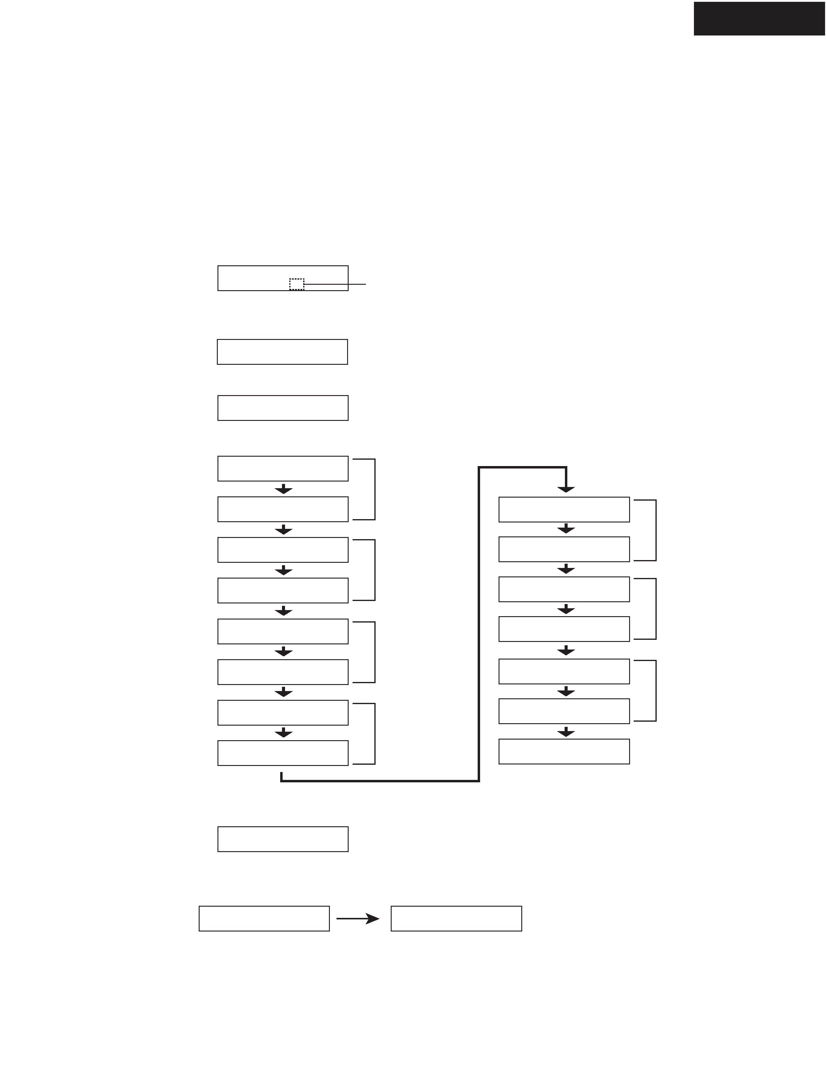
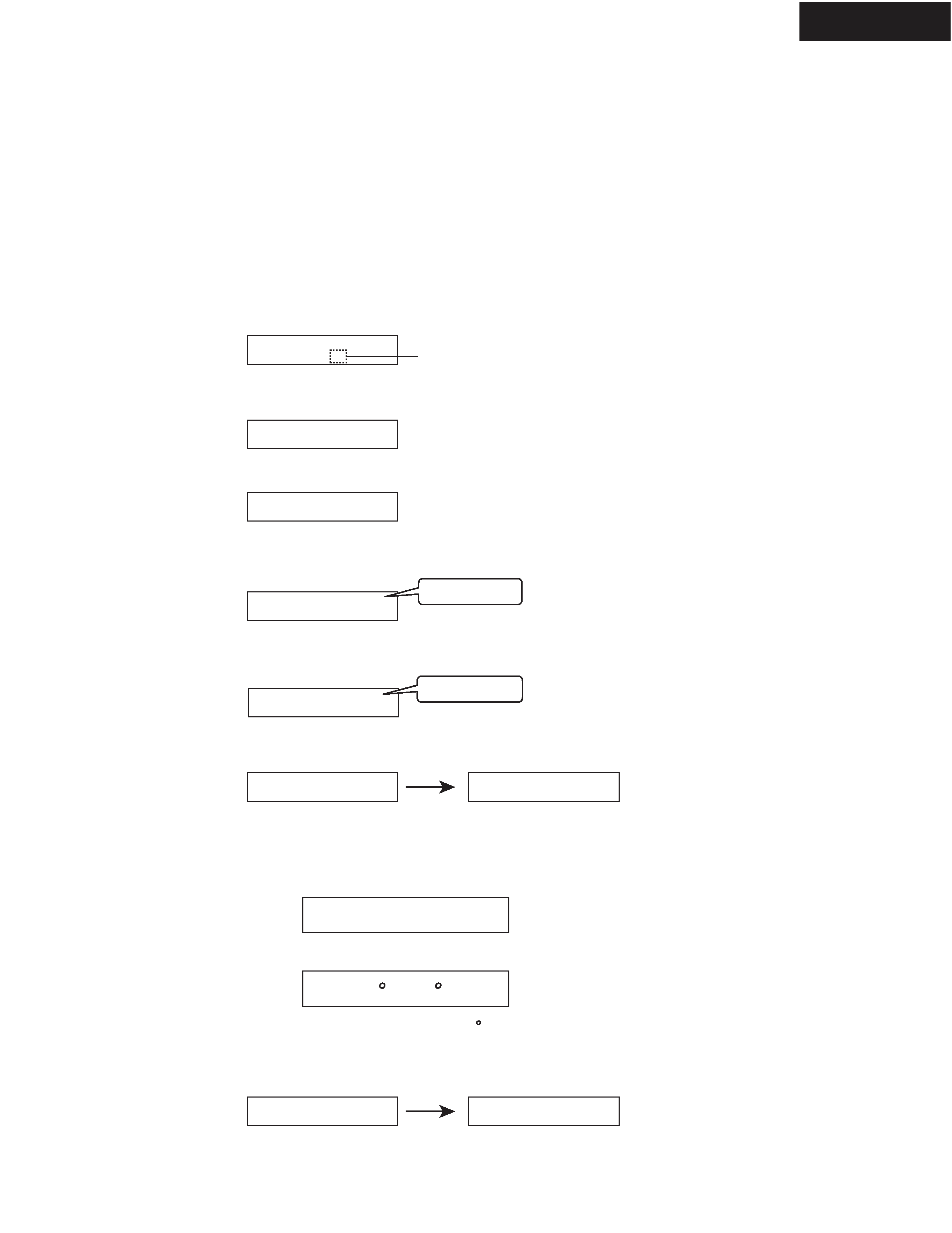
OPERATION CHECK-1
SPEAKER PROTECT-1 (DC VOLTAGE DETECTION)
1. Press and hold down CD button, then press STANDBY/ON button while the unit is Power ON.
" Test - _ " is displayed only for 5 seconds.
2. Press VIDEO 3 button, while the characters of " Test - _ " are displayed.
The unit will be in the state of " Test-4-00 ".
3. Repeatedly press TONE
+ button until the characters of " Test-4-21 " are displayed.
[Procedure]
<Note>
No load. No input signal.
Test - _
Test - 4-00
[When]
1. Exchange power transistors (Q6050 - Q6056, Q6060 - Q6066).
2. Exchange amplifier PC board ass'y (NAAF-8678, NAAF-8682).
Test - 4-21
Check whether the operation starts and continues automatically as follows.
Test - 4-21
Test - 4-22
Test - 4-25
Test - 4-23
Test - 4-24
Protect OK
Protect OK
Protect
Protect OK
Protect OK
Protect OK
Test - 4-35
Clear
Turn off
Front L ch
Check
If all channels are OK, the characters of " Test - 4 - 35 " are finally displayed.
4. Press STANDBY/ON button.
Front R ch
Check
Center ch
Check
Surround L ch
Check
Surround R ch
Check
Blinks
Test - 4-26
Protect OK
Surround Back L ch
Check
Test - 4-27
Protect OK
Surround Back R ch
Check
TX-SR804/804E
TX-SR804/804E
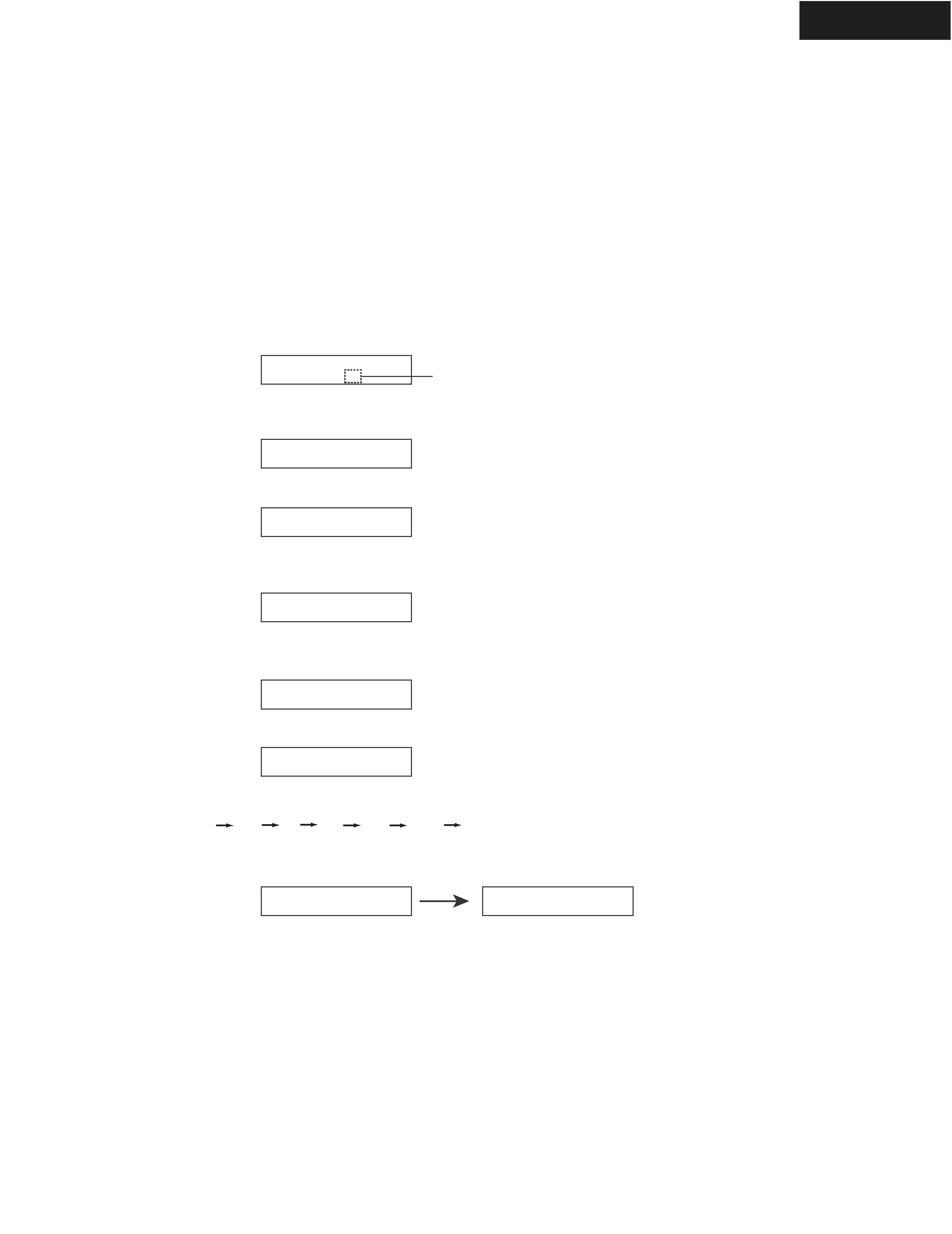
OPERATION CHECK-2
SPEAKER PROTECT-2 (CURRENT DETECTION)
1. Press and hold down CD button, then press STANDBY/ON button while the unit is Power ON.
" Test - _ " is displayed only for 5 seconds.
2. Press VIDEO 3 button, while " Test - _ " is displayed.
The unit will be in the state of " Test-4-00 ".
3. Repeatedly press TONE
+ button until " Test-4-35 " is displayed.
4. Connect a dummy load of 3 ohms to the Front L ch speaker terminals.
At this time, confirm that the speaker relay is not turned off.
5. Connect a dummy load of 1 ohm to the Front L ch speaker terminals.
At this time, confirm that the speaker relay is turned off and " Protect " will bev displayed.
Disconnect the dummy load immediately after checking the display of " Protect ".
6. Check other channels according to the same procedure as 4 and 5.
[Procedure]
<Note>
No input signal.
Do not check two or more channels at the same time.
Do not connect a dummy load to speaker terminals longer than 2 seconds.
Test - _
Test - 4-00
[When]
1. Exchange power transistors (Q6050 - Q6056, Q6060 - Q6066).
2. Exchange amplifier PC board ass'y (NAAF-8678, NAAF-8682).
Test - 4-35
Clear
Turn off
7. Press STANDBY/ON button.
Test - 4-35
Protect
Test - 4-35
Blinks
FL
FR
C
SL
SR
SBL
SBR
TX-SR804/804E
OPERATION CHECK-3
CONTROL OF POWER SUPPLY (SPEAKER OUTPUT SENSOR AND THERMAL DETECTOR)
Test - _
Test - 4-00
Test - 4-36
Clear
Turn off
Test - 4-36
FM STEREO
Blinks
Ver. 1.01/06920a
<Ex.>
<Ex.>
T: 25 C/ 77 F
Clear
Turn off
Output Sensor
1. Press and hold down CD button, then press
STANDBY/ON button while the unit is Power ON.
" Test - _ " will be displayed only for 5 seconds.
2. Press VIDEO 3 button while " Test - _ " is displayed.
The unit will be in the state of " Test-4-00 ".
3. Repeatedly press TONE
+ button until " Test-4-36 " is displayed.
4. At this time, confirm that the red characters of " FM STEREO " is displayed.
And, confirm that the relays (RL6901 and RL6902) are turned off in 2 or 3 seconds. (FL+FR+C+SL check)
6. Press STANDBY/ON button.
[Procedure]
<Note>
No output. No input.
[When]
1. Exchange power transistors (Q6050 - Q6056, Q6060 - Q6066).
2. Exchange power amplifier PC board ass'y (NAAF-8678, NAAF-8682).
3. Exchange thermal sensor PC board ass'y (NAETC-8680).
Thermal Detector
1. Press and hold down DISPLAY button, then press STANDBY button when the unit is power ON.
The main microprocessor version will be displayed only for 3 seconds.
2. Press TONE button while the version is displayed, then the temperature will be displayed.
3. Confirm that the displayed temperature is within +/-20 C from the ambient temperatures.
4. Press STANDBY/ON button.
Test - 4-37
5. Press TONE
+ button and confirm that the red characters of " FM STEREO " is displayed and
the relays (RL6901 and RL6902) are turned off in 2 or 3 seconds as well as 4. (C+SR+SBL+SBR check)
FM STEREO