BMDD
120V AC, 60Hz
BMPP,BMPA,SMPP,GMPA
230~240V AC, 50Hz
BMWT,GMWT,GMWR
120/220~230V AC, 50/60Hz
GMGK
220V AC, 50Hz
TX-SR700/E
SERVICE MANUAL
SERVICE MANUAL
AV RECEIVER
Black, Golden and Silver models
MODEL
TX-SR700/E
Ref. No. 3731
062002
RC-482M
SAFETY-RELATED COMPONENT
WARNING!!
COMPONENTS IDENTIFIED BY MARK
ON THE
SCHEMATIC DIAGRAM AND IN THE PARTS LIST ARE
CRITICAL FOR RISK OF FIRE AND ELECTRIC SHOCK.
REPLACE THESE COMPONENTS WITH ONKYO
PARTS WHOSE PART NUMBERS APPEAR AS SHOWN
IN THIS MANUAL.
MAKE LEAKAGE-CURRENT OR RESISTANCE
MEASUREMENTS TO DETERMINE THAT EXPOSED
PARTS ARE ACCEPTABLY INSULATED FROM THE
SUPPLY CIRCUIT BEFORE RETURNING THE
APPLIANCE TO THE CUSTOMER.
Page 1

AMPLIFIER SECTION
Continuous average power output (FTC)
All channels:
100W per channel min. RMS at 8 ohm,
2 channels driven from 20 Hz to 20
kHz with no more than 0.08% total
harmonic distortion.
125 W min. RMS at 6 ohm, 2 channels
driven from 1 kHz with no more
than 0.1% total harmonic distortion.
Continuous power output (DIN) 130 W at 6 ohm
Maximum power output (EIAJ)
160 W at 6 ohm
Dynamic power output (stereo)
2
250 W at 3 ohm
2
210 W at 4 ohm
2
130 W at 8 ohm
Total harmonic distortion:
0.08% at rated power
0.08% at 1 W output
IM distortion:
0.08% at rated power
0.08% at 1 W output
Damping factor:
60 at 8 ohm
Input sensitivity and impedance
LINE (CD, TAPE, DVD,
VIDEO 1-4):
200 mV, 47 kohm
MULTICHANNEL INPUT
(FRONT L/C/R, SURROUND
L/R):
200 mV, 47 kohm
(SUBWOOFER):
36 mV, 47 kohm
COAXIAL (DIGITAL):
0.5 Vp-p, 75 ohm
DVD, VIDEO 1, 2, 3, 4:
1 Vp-p, 75 ohm
1 Vp-p, 75 ohm (Y)
0.28 Vp-p, 75 ohm (C)
COMPONENT VIDEO 1, 2:
1 Vp-p, 75 ohm (Y)
0.7 Vp-p, 75 ohm (PB, PR)
Output level and impedance
Rec out (TAPE, VIDEO 1):
200 mV, 470 ohm
Pre out:
1 V, 470 ohm
VIDEO (VIDEO 1,
MONITOR OUT):
1 Vp-p, 75 ohm
1 Vp-p, 75 ohm (Y)
0.28 p-p, 75 ohm(C)
COMPONENT VIDEO OUT:
1 Vp-p, 75 ohm (Y)
0.7 Vp-p, 75 ohm (PB, PR)
Frequency response:
10 Hz to 100 kHz:+1/-3 dB
(CD in Direct mode)
Tone control
Bass:
±12 dB at 50 Hz
Treble:
±12 dB at 20,000 Hz
Signal-to-noise ratio (stereo)
CD/Tape:
100 dB (IHF A, 0.5 V input)
Muting:
- 50 dB
TUNER SECTION
FM
Tuning range:
87.5-108.0 MHz (50-kHz steps)
Usable sensitivity
Mono:
11.2 dBf, 1.0 µV (75 ohm IHF)
0.9 µV (75 ohm DIN)
Stereo:
17.2 dBf, 2.0 µV (75 ohm IHF)
23 µV (75 ohm DIN)
50 dB quieting sensitivity
Mono:
17.2 dBf, 2.0 µV (75
ohm )
Stereo:
37.2 dBf, 20 µV (75
ohm )
Capture ratio:
2.0 dB
Image rejection ratio
USA & Canadian models:
40 dB
Other area models:
85 dB
IF rejection ratio:
90 dB
Signal-to-noise ratio
Mono:
76 dB
Stereo:
70 dB
Alternate channel attenuation:
55 dB
Selectivity:
50 dB (DIN)
AM suppression ratio:
50 dB
Total harmonic distortion
Mono:
0.2%
Stereo:
0.3%
Frequency response:
30 Hz - 15 kHz, ±1.0 dB
Stereo separation:
45 dB at 1 kHz
30 dB at 100 Hz -10 kHz
AM
Tuning range
USA & Canadian models:
530 to 1,710 kHz (10-kHz steps)
European & Australian models: 522 to 1,611 kHz (9-kHz steps)
Worldwide models:
531 to 1,602 kHz (9-kHz steps)
530 to 1,710 kHz (10-kHz steps)
Usable sensitivity:
30 µV
Image rejection ratio:
40 dB
IF rejection ratio:
40 dB
Signal-to-noise ratio:
40 dB
Total harmonic distortion:
0.7%
GENERAL
Power supply
USA & Canadian models:
AC 120 V, 60 Hz
European & Australian models: AC 230 - 240 V, 50 Hz
Some Asian models:
AC 220 - 230 V, 50/60 Hz
Worldwide models:
AC 220 - 230 and 120 V
50/60 Hz
Power consumption
USA & Canadian models:
6.7 A
Other models:
550 W
Dimensions (W H
D):
435
175 431.5 mm
17-1/8"
6-7/8" 16-15/16"
Weight
USA & Canadian models:
27.8 lbs.
Other models:
13.1 kg
REMOTE CONTROLLER
Transmitter:
Infrared
Signal range:
Approx. 16 ft., 5 meters
Power supply:
Two "AA" batteries (1.5 V 2)
Specifications and features are subject to change without notice.
RIAA deviation:
20 Hz to 20 kHz:±0.8 dB
Phono overload:
70mV RMS at 1 kHz,0.5% T.H.D.
Phono:
80 dB (IHF A, 5 m V input)
PHONO:
2.5 mV, 47 k ohm
switchable,
TX-SR700/E
SPECIFICATIONS
Page 2
4. Memory Preservation
This unit does not require memory preserv ation batteries. A
built-in memory power back-up system preserves the contents
of the memory during po wer f ailures and e ven when the unit is
unplugged. The unit must be plugged in order to char ge the
back-up system.
The memory preserv ation period after the unit has been
unplugged v aries depending on climate and placement of the
unit. On the average, memory contents are protected over a
period of a fe w weeks after the last time the unit has been
unplugged. This period is shorter when the unit is e xposed to a
highly humid climate.
2. To initialize the unit
This device employs a microprocessor to perform various
functions and operations. If interference generated by an external
power supply, radio wave, or other electrical source results in
accident which causes the specified operations and functions to
operate abnormally.
To perform a result, please follow the procedure below.
1.Press and hold down the VIDEO-1 button, then press the
STANDBY/ON button.
2.After "clear" is displayed, the preset memory and each
mode stored in the memory, such as surround, are
initialized and will return to the factory setting.
3. Safety-check out
(Only U.S.A. model)
After correcting the original service problem, perform the
following safety check before releasing the set to the customer.
Connect the insulating-resistance tester between the plug of power
supply cord and screw on the back panel.
Specifications: 3.3Mohm+/-10% at 500V.
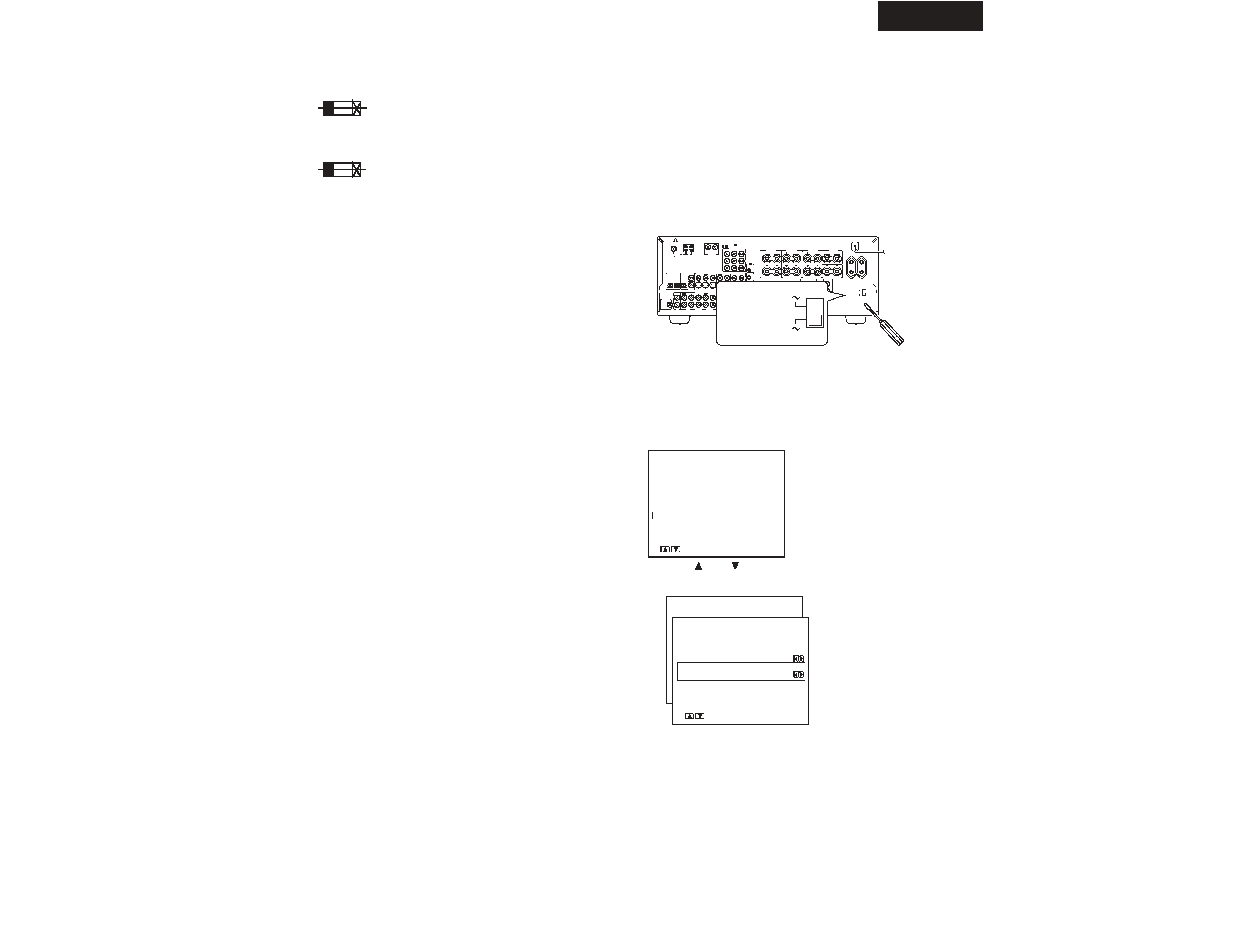
1. Replacing the fuses
This symbol located near the fuses indicates that the
fuse used is fast operating type. For continued protection against
fire hazard, replace with same type fuse. For fuse rating refer to
the marking adjacent to the symbol.
Ce symbole indique que le fusible utlise est a rapide.
Pour une protection permanente, n'untiliser que fusibles de
meme type. Ce darnier est la qu le present symbol est
appse.
CIRCUIT NO. PART NO.
DESCRIPTION
Note: <D>:120V model only
<O>: Other models except 120V model
<T>: Asian model only for 230V
<R>: Chinese model only
5.Setting the voltage selector (Worldwide models
only)
Worldwide models are equipped with a voltage selector to conform
with local power supplies. Be sure to set this switch to match the
voltage of the power supply in your area before plugging in the unit.
Determine the proper voltage for your area: 220-230 V or 120 V. If
the preset voltage is not correct for your area, insert a screwdriver
into the groove in the switch. Slide the switch all the way to the
upper (120 V) or to the lower (220-230 V), whichever is appropriate.
6.Setting the AM tuning step frequency
(Worldwide models only)
1. Press the MENU button on the front panel or SETUP
button on the remote controller.
The main menu appears.
* Menu *****************
1.Speaker Config
2.Speaker Distance
3.Level Calibration
4.Input Setup
5.OSD Setup
6.Preference
|ENTER|Quit:|SETUP|
2. Use the
and
cursor buttons to select " 6.
Preference
" and then press the ENTER button.
* Menu *****************
1.Speaker Config
2.Speaker Distance
3.Level Calibration
4.Input Setup
5.OSD Setup
6.Preference
6.Preference
***********************
a.Headphones Level
: 0dB
b.AM Frequency Step
:9 kHz
Quit:|SETUP|
b. AM Frequency Step
This setting only appears on the worldwide model. It determines the
increment amount or decrement amount when adjusting the AM
tuner frequency. The initial setting is 9 kHz, and this needs only to be
changed if you are using the unit in a 10-kHz region.
F6901,F6902
252100
10A-EAK,Fuse <O>
252196
12A-UL/T-314,Fuse <D>
F901
252199
10A-UL,Fuse <D/T/R>
F902
252078,
5A-SE-EAK,
252244 or
5A-SE-TL250V or
252278
5A-SE-TL250V,Fuse <O>
F903
252075,
2.5A-SE-EAK,
252241 or
2.5A-SE-TL250V or
252275
2.5A-SE-TL250V,Fuse <O>
F9501
252160 or
2.5A-UL/T-237 or
252254
2.5A-T/UL-ST2,Fuse <D>
252075,
2.5A-SE-EAK,
252241 or
2.5A-SE-TL250V or
252275
2.5A-SE-TL250V,Fuse <O>
L
27122974
REMOTE
CONTROL
CAUTION: SPEAKER IMPEDANCE
6 OHMS MIN. /SPEAKER
ANTENNA
FM
75
AM
COAXIAL
OPTICAL
1
2
IN
IN
IN
IN
FRONT
SURR
CENTER
SUB
WOOFER
VIDEO 2
VIDEO 1
OUT
OUT
DIGITAL INPUT
VIDEO 2
DVD
MONITOR
OUT
DVD
TAPE
CD
SUBWOOFER
PRE OUT
L
R
FRONT
SPEAKERS
ZONE 2
SPEAKERS
SURROUND
SPEAKERS
CENTER
SPEAKER
R
L
R
L
FRONT SURROUND
CENTER
ZONE 2
SURROUND
BACK
R
L
R
L
PRE OUT
R
VIDEO 3
VIDEO 1
V
12V
TRIGGER
OUT
ZONE 2
VIDEO 3
OPTICAL
COAXIAL
DIGITAL
INPUT
IN
IN
IN
OUT
IN
DIGITAL
OUTPUT
IN
INPUT 1
INPUT 2
OUTPUT
COMPONENT VIDEO
L
R
PHONO IN
PR
PB
Y
GND
OUT
OUT
S
IR
IN
SURROUND
BACK
SPEAKER
AC OUTLETS
AV RECEIVER
MODEL NO.
TX-SR700E
120V
VOLTAGE
SELECTOR
220-230V
SWITCHED
TOTAL 100W MAX.
120V
VOLTAGE
SELECTOR
220-230V
TX-SR700/E
SERVICE PROCEDURES
Page 3
1
2
4
5
6
7
8
9
10
11
13
14
15
16
21
22
23
24
25
26
31
32
33
34
41
51
52
F6901
F901
F902
F9501
P101
P2602
P6931
P7501
P7502
P901
Q6050
Q6066
Q6056
Q6060
T901
U1
U2
U3
U4
U5
U6
U11
U12
U8
U14
U15
U16
U18
U17
U19
U20
U21
U27
U28
U24
U26
U29
U31
U32
U36
42
42
9
42
4
4
4
14
6
3
12
46
47
48
24
F6902
U23
36
36
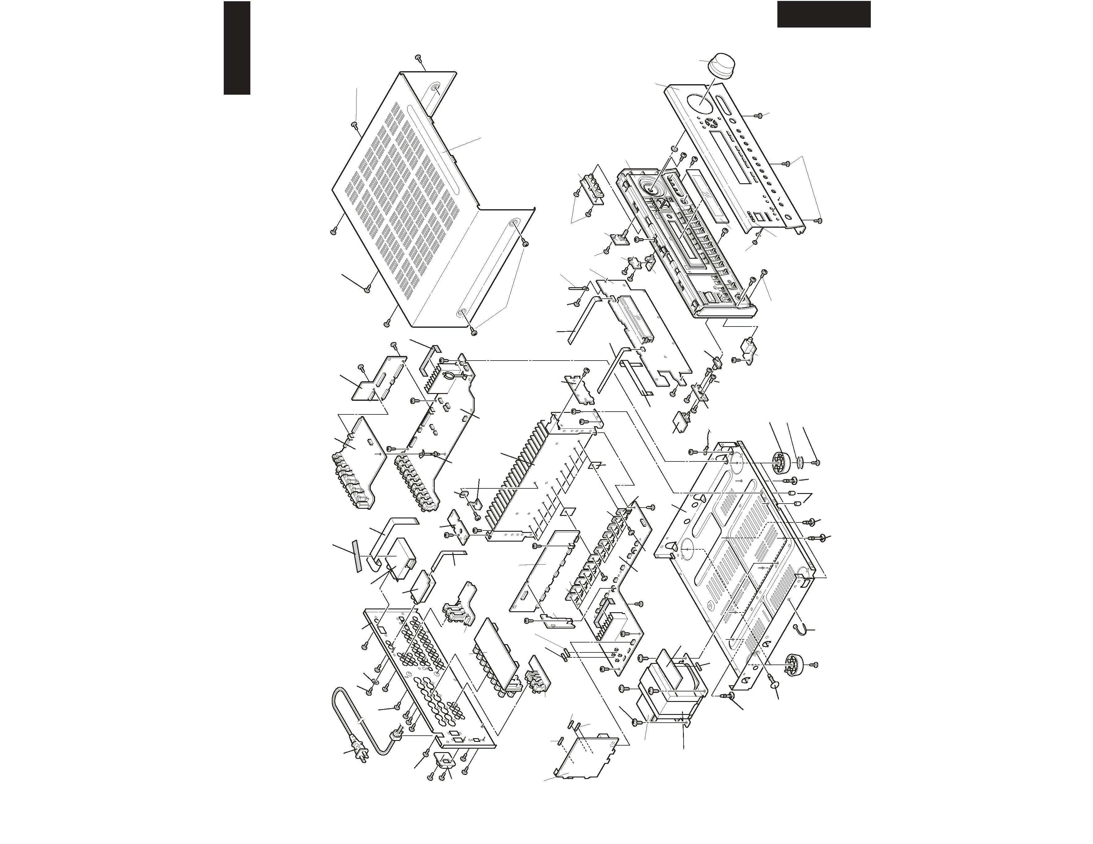
TX-SR700/E
EXPLODED VIEW
TX-SR700/E
F903
Page 4
REF.NO.
PART NO.
DESCRIPTION
T901
2301587
!
NPT-1439D,Power transformer <D>
2301588
!
NPT-1439P,Power transformer <P/A>
2301589
!
NPT-1439DG,Power transformer <T/R/K>
U1
1A929560-1N
NADG-7460-1N,Main circuit PC board ass'y <D>
1A929560-1O
NADG-7460-1O,Main circuit PC board ass'y <P>
1A929560-1P
NADG-7460-1P,Main circuit PC board ass'y <A/K>
1A929560-1Q
NADG-7460-1Q,Main circuit PC board ass'y <T/R>
U2
1A929561-1N
NADIS-7461-1N,Display circuit PC board ass'y <D>
1A929561-1O
NADIS-7461-1O,Display circuit PC board ass'y <O>
U3
1A929562-1N
NASW-7462-1N,Volume PC board ass'y <D>
1A929562-1O
NASW-7462-1O,Volume PC board ass'y <O>
U4
1A929563-1N
NAETC-7463-1N,Headphone terminal PC board ass'y <D>
1A929563-1O
NAETC-7463-1O,Headphone terminal PC board ass'y <O>
U5
1A929564-1N
NAVD-7464-1N,Video terminal PC board ass'y <D>
1A929564-1O
NAVD-7464-1O,Video terminal PC board ass'y <O>
U6
1A929565-1N
NAVD-7465-1N,Component video terminal PC board ass'y <D>
1A929565-1O
NAVD-7465-1O,Component video terminal PC board ass'y <O>
U8
1A929567-1N
NAVD-7467-1N,Front video PC board ass'y <D>
1A929567-1O
NAVD-7467-1O,Front video PC board ass'y <O>
U11
1A929570-1N
NADG-7470-1N,Front optical input PC board ass'y <D>
1A929570-1O
NADG-7470-1O,Front optical input PC board ass'y <O>
U12
1A929571-1N
NAETC-7471-1N,PC board for holder <D>
1A929571-1O
NAETC-7471-1O,PC board for holder <O>
U14
1A929573-1N
NAAF-7473-1N,Equalizer amplifier PC board ass'y <D>
1A929573-1O
NAAF-7473-1O,Equalizer amplifier PC board ass'y <O>
U15
1A929574-1N
NAAF-7474-1N,Power amplifier PC board ass'y <D>
1A929574-1O
NAAF-7474-1O,Power amplifier PC board ass'y <O>
U16
1A929576-1N
NAETC-7476-1N,Speaker terminal PC board ass'y <D>
1A929576-1O
NAETC-7476-1O,Speaker terminal PC board ass'y <O>
U17
1A929577-1N
NAPS-7477-1N,Secondary circuit PC board ass'y <D>
1A929577-1O
NAPS-7477-1O,Secondary circuit PC board ass'y <O>
U18
1A929578-1N
NAETC-7478-1N,Preoutput PC board ass'y <D>
1A929578-1O
NAETC-7478-1O,Preoutput PC board ass'y <O>
U19
1A929579-1N
NAETC-7479-1N,PC board for holder <D>
1A929579-1O
NAETC-7479-1O,PC board for holder <O>
U20
1A929580-1N
NAETC-7480-1N,Thermal detector PC board ass'y <D>
1A929580-1O
NAETC-7480-1O,Thermal detector PC board ass'y <O>
U21
1A929581-1N
NAETC-7481-1N,PC board for holder <D>
1A929581-1O
NAETC-7481-1O,PC board for holder <O>
U23
1A929583-1N
NAAF-7483-1N,Driver circuit PC board ass'y <D>
1A929583-1O
NAAF-7483-1O,Driver circuit PC board ass'y <P>
1A929583-1P
NAAF-7483-1P,Driver circuit PC board ass'y <A>
1A929583-1Q
NAAF-7483-1Q,Driver circuit PC board ass'y <R>
1A929583-1R
NAAF-7483-1R,Driver circuit PC board ass'y <T>
1A929583-1U
NAAF-7483-1U,Driver circuit PC board ass'y <K>
REF.NO.
PART NO.
DESCRIPTION
U24
1A929584-1N
NAPS-7484-1N,Primary circuit PC board ass'y <D>
1A929584-1O
NAPS-7484-1O,Primary circuit PC board ass'y <P>
1A929584-1P
NAPS-7484-1P,Primary circuit PC board ass'y <A>
1A929584-1Q
NAPS-7484-1Q,Primary circuit PC board ass'y <R>
1A929584-1R
NAPS-7484-1R,Primary circuit PC board ass'y <T>
1A929584-1U
NAPS-7484-1U,Primary circuit PC board ass'y <K>
U26
1A929586-1N
NAETC-7486-1N,Connector PC board ass'y <D>
1A929586-1O
NAETC-7486-1O,Connector PC board ass'y <P>
1A929586-1P
NAETC-7486-1P,Connector PC board ass'y <A>
1A929586-1Q
NAETC-7486-1Q,Connector PC board ass'y <R>
1A929586-1R
NAETC-7486-1R,Connector PC board ass'y <T>
1A929586-1U
NAETC-7486-1U,Connector PC board ass'y <K>
U27
1A929587-1O
NASW-7487-1O,Power switch PC board ass'y <P>
1A929587-1P
NASW-7487-1P,Power switch PC board ass'y <A>
1A929587-1Q
NASW-7487-1Q,Power switch PC board ass'y <R>
1A929587-1R
NASW-7487-1R,Power switch PC board ass'y <T>
1A929587-1U
NASW-7487-1U,Power switch PC board ass'y <K>
U28
1A929588-1O
NAETC-7488-1O,PC board for holder <P>
1A929588-1P
NAETC-7488-1P,PC board for holder <A>
1A929588-1Q
NAETC-7488-1Q,PC board for holder <R>
1A929588-1R
NAETC-7488-1R,PC board for holder <T>
1A929588-1U
NAETC-7488-1U,PC board for holder <K>
U29
1A929589-1N
NAPS-7489-1N,Terminal PC board ass'y <D>
1A929589-1O
NAPS-7489-1O,Terminal PC board ass'y <P>
1A929589-1P
NAPS-7489-1P,Terminal PC board ass'y <A>
1A929589-1Q
NAPS-7489-1Q,Terminal PC board ass'y <R>
1A929589-1R
NAPS-7489-1R,Terminal PC board ass'y <T>
1A929589-1U
NAPS-7489-1U,Terminal PC board ass'y <K>
U31
1A929591-1N
NAETC-7491-1N,PC board for holder <D>
1A929591-1O
NAETC-7491-1O,PC board for holder <P>
1A929591-1P
NAETC-7491-1P,PC board for holder <A>
1A929591-1Q
NAETC-7491-1Q,PC board for holder <R>
1A929591-1R
NAETC-7491-1R,PC board for holder <T>
1A929591-1U
NAETC-7491-1U,PC board for holder <K>
U32
1A929592-1N
NAETC-7492-1N,PC board for holder <D>
1A929592-1O
NAETC-7492-1O,PC board for holder <P>
1A929592-1P
NAETC-7492-1P,PC board for holder <A>
1A929592-1Q
NAETC-7492-1Q,PC board for holder <R>
1A929592-1R
NAETC-7492-1R,PC board for holder <T>
1A929592-1U
NAETC-7492-1U,PC board for holder <K>
U33
1A929593-1U
NAPS-7493-1U,AC outlet PC board ass'y <K>
U36
240138A,
ENG06501QR,
240134A or
TFCE1U114B or
240141
FAE350-A13F,Tuner unit <D>
240139A,
ENG07501QR,
240135 or
TFCE1E512A or
240142
FAE404-E13F,Tuner unit <O>
NOTE: THE COMPONENTS IDENTIFIED BY MARK !
ARE CRITICAL FOR RISK OF FIRE AND
ELECTRIC SHOCK. REPLACE ONLY WITH
PART NUMBER SPECIFIED.
Note:
<D>: 120V model only
<P>: European model only
<T>: 230-240 model only
<K>: Korean model only
<A>: Australian model only
<R>: Chinese model only
<O>: Other models except
120V model
TX-SR700/E
EXPLODED VIEW-PARTS LIST 2
TX-SR700/E
Page 5