TX-DS898
SAFETY-RELATED COMPONENT
WARNING!!
COMPONENTS IDENTIFIED BY MARK
ON THE
SCHEMATIC DIAGRAM AND IN THE PARTS LIST ARE
CRITICAL FOR RISK OF FIRE AND ELECTRIC SHOCK.
REPLACE THESE COMPONENTS WITH ONKYO
PARTS WHOSE PART NUMBERS APPEAR AS SHOWN
IN THIS MANUAL.
MAKE LEAKAGE-CURRENT OR RESISTANCE
MEASUREMENTS TO DETERMINE THAT EXPOSED
PARTS ARE ACCEPTABLY INSULATED FROM THE
SUPPLY CIRCUIT BEFORE RETURNING THE
APPLIANCE TO THE CUSTOMER.
SERVICE MANUAL
AV RECEIVER
Black, Golden and Silver models
MODEL
TX-DS898
092001
BMDD
BMPP,SMPP,BMPA,GMPA
BMWT,GMWT,GMWR
GMGT
120V AC, 60Hz
230-240V AC, 50Hz
120/220-230V AC, 50/60Hz
220V AC, 50Hz
STANDBY/ON
OFF
ON
POWER
STANDBY
MASTER VOLUME
FM
AM
PHONO
C D
TAPE
DVD
VIDEO
3
VIDEO
5
VIDEO
4
VIDEO
2
VIDEO
1
ZONE
2 (
)
GRN
REC (
)
RED
AUDIO
SELECTOR
DISPLAY
PURE AUDIO
UPSAMPLING
TX-DS
898
PUSH TO OPEN
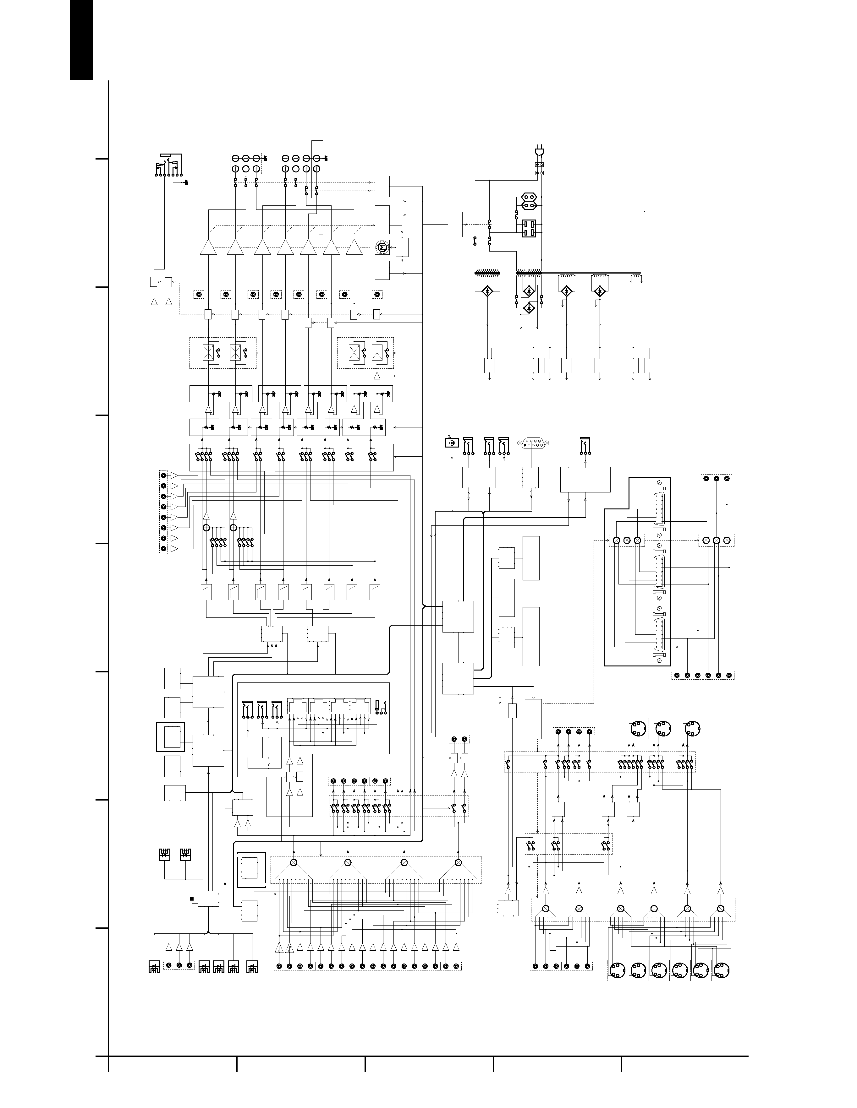
TX-DS898
BLOCK DIAGRAM
A
1
2
3
4
5
B
C
D
E
F
G
H
S U R R O U N D S P E A K E R S
L E F T
R I G H T
S U R R O U N D B A C K S P E A K E R S
/ Z O N E 2 S P E A K E R S
R I G H T / B A C K
L E F T
D C 2 4 V
4 A I N
M U L T I C H A N N E L I N P U T
L
R
C
S W
S L
S R
S B L
S B R
1 4
8
7
1
D 4 V I D E O O U T P U T
1 4
8
7
1
D 4 V I D E O I N P U T 2
1 4
8
7
1
D 4 V I D E O I N P U T 1
F R O N T S P E A K E R S
R I G H T
L E F T
C E N T E R
C O M P
R E C / Z 2
C O M P
I N P
C
R E C / Z 2
C
I N P
Y
R E C / Z 2
R I G H T
R E C / Z 2
A C O U T L E T
F U S E
F U S E
R S 2 3 2
Y
C
V I D E O 1
Y
C
S - V I D E O O U T P U T
M O N I T O R
Y
C
V I D E O 2
Y
C
V I D E O 5
( F R O N T )
Y
C
S - V I D E O I N P U T
D V D
Y
C
V I D E O 1
Y
C
V I D E O 2
Y
C
V I D E O 3
Y
C
V I D E O 4
R I G H T
P R E O U T
L E F T
S U R R O U N D
L E F T
S U R R O U N D
R I G H T
S U R R O U N D
B A C K
/ Z O N E 2 L E F T
S U R R O U N D
B A C K
/ Z O N E 2 R I G H T
C E N T E R
S U B W O O F E R
C O O L I N G F A N
I R
D E -
M O D U L A T O R
M U T E
M U T E
I R 5 6 K
R E -
M O D U L A T O R
1 2 V
T R I G G E R
C O N T R O L
I R
D E -
M O D U L A T O R
1 2 V T R I G G E R
+ B 3
R E L A Y
+ B 2
R E L A Y
D R I V E R
F L A C
F L T U B E
F L A C
M A I N A M P
+ B 1 / - B 1
- 2 7 V
- V P
- 1 5 V
A U D I O
- 5 V
V I D E O
+ 5 V
V I D E O
+ 5 V
D S P
+ 1 5 V
A U D I O
I S D E T
R E L A Y
D R I V E R
V O L T A G E S E N S O R
C U R R E N T S E N S O R
T H E R M A L
S E N S O R
F A N
D R I V E R
R I
I N T E R F A C E
+ 5 . 6 V
S T A N D B Y
Z O N E 2
L I N E O U T
L
R
L V I D E O 2
R
V I D E O 5 L
R
( F R O N T )
2 4 . 5 7 6 M H Z
R E C O U T
L T A P E
R
L V I D E O 1
R
C O M P O S I T E
V I D E O O U T
M O N I T O R
V I D E O 1
V I D E O 2
Z O N E 2
V I D E O 3 L
R
V I D E O 4 L
R
V I D E O 1 L
R
V I D E O 2 L
R
T A P E L
R
D V D L
R
A U D I O I N P U T
P H O N O L
R
C D L
R
C O A X I A L 1
C O A X I A L 2
C O A X I A L 3
C O M P O N E N T V I D E O O U I T P U T
Y
C B
C R
C O M P O N E N T
V I D E O
1
Y
C B
C R
I N P U T
2
Y
C B
C R
V I D E O 3
V I D E O 4
V I D E O 5
( F R O N T )
C O M P O S I T E V I D E O I N P U T
D V D
V I D E O 1
V I D E O 2
H E A D P H O N E
R E M O T E S E N S O R
I R O U T 1
4 0 K
I R O U T
5 6 K
I R O U T
I R O U T 2
4 0 K
I R I N
R I
T 9 0 2
T 9 0 1
A C I N
T O N E
N J U 7 3 0 6 G
N J U 7 3 0 6 G
O P T I C A L 1
D I G I T A L A U D I O O U T P U T
O P T I C A L 2
O P T I C A L 4
O P T I C A L 3
O P T I C A L 1
O P T I C A L 2
D I G I T A L A U D I O I N P U T
O P T I C A L
V I D E O 5
( F R O N T )
S U B M P U
C S 4 9 3 0 0 2
P O S T
P R O C E S S I N G
( T H X C I N E M A )
( T H X S U R R O U N D E X )
C S 4 9 3 0 0 2
D E C O D I N G
( A C - 3 , D T S , A A C )
( D T S - E S )
( P L I I , N E O : 6 )
M A I N M P U
- 1
- 1
Z O N E D
Z O N E C
Z O N E B
Z O N E A
A - B U S
B U 1 9 2 3
R D S
D E C O D E R
T C 9 2 4 6 F
2 N D P L L
F M / A M
T U N E R
P A C K
M P D 4 4 1 0 0 0
S R A M
1 M M I N .
M P D 4 4 1 0 0 0
S R A M
1 M M I N .
M B M 2 9 L V 0 0 2
F L A S H R O M
2 M M I N .
M B M 2 9 L V 0 0 2
F L A S H R O M
2 M M I N .
L E D D R I V E R
M 6 6 0 0 4 F P
F L D R I V E R
O S D
L C 7 4 7 6 1
- 9 1 8 9
A K 4 3 5 6
1 9 2 / 2 4
D / A
A K 4 5 2 8
9 6 / 2 4
D / A
( 2 / 2 )
A K 4 5 2 8
9 6 / 2 4
A / D
( 1 / 2 )
A K 4 1 1 4
D I R
M P D 4 7 2 1 G S
R S 2 3 2
I N T E R F A C E
5 0 K L P F
5 0 K L P F
5 0 K L P F
5 0 K L P F
5 0 K L P F
5 0 K L P F
5 0 K L P F
5 0 K L P F
T C 9 4 A 0 7 F
T C 9 4 A 0 7 F
T C 9 4 A 0 7 F
M A S T E R V O L U M E
T C 9 4 A 0 7 F
C U T
B O O S T
T C 9 4 8 2 F
M C L
B L
T L
D L
B R
T R
M C R
D R
Z 2 R
Z 2 L
D S B L
M C S R
M C S B L
D S W
M C S W
D C
M C C
D S B R
M C S B R
D S R
D S L
M C S L
B P L S
S W - > R
B P L S
S W - > L
B Y P A S S
B Y P A S S
C - > L
S L - > L
C - > R
S R - > R
B Y P A S S
B Y P A S S
T V - 5
P O W E R S W
T V - 8
Z O N E 2
R X 0
R X 1
H P E N
R X 2
R X 3
T X 0
R X 4
R X 5
D A U X
R X 6
R X 7
B
P
L
S
J a p a n m o d e l o n l y
D T R - 8 . 2 / 7 . 2 o n l y
- 6 d B
- 6 d B
Z o n e 2 L E D
R e c O u t L E D
E x c e p t f o r M D D
T C 9 2 7 4 N - 0 0 8
T C 9 2 7 3 F - 0 1 7
J a p a n m o d e l o n l y
E u r o p e a n m o d e l o n l y
1 5 d B / 3 0 d B
T C 9 1 6 3
T C 9 1 6 4
T C 9 2 7 3 N - 0 0 4
+ 2 9 d B
P o w e r A m p l i f i e r
+ 2 9 d B
1 1 d B
1 1 d B
R N 1 2 4 1 x 2 2
P A L
N T S C
S E P
S E P
Y - C
Y - C
M I X
Y - C
R N 1 2 4 1 x 6
F L T
V o l u m e C o n t r o l
K e y M a t r i x
0 d B
6 d B
6 d B
+ 2 9 d B
+ 2 9 d B
+ 2 9 d B
+ 2 9 d B
+ 2 9 d B
6 d B
6 d B
6 d B
6 d B
7 4 H C 4 0 5 1 x 6
M U T E
M U T E
M U T E
M U T E
M U T E
M U T E
M U T E
M U T E
M U T E
M U T E
M U T E
M U T E
M U T E
M U T E
TX-DS898
ADJUSTMENT AND CONFIRMATION PROCEDURES
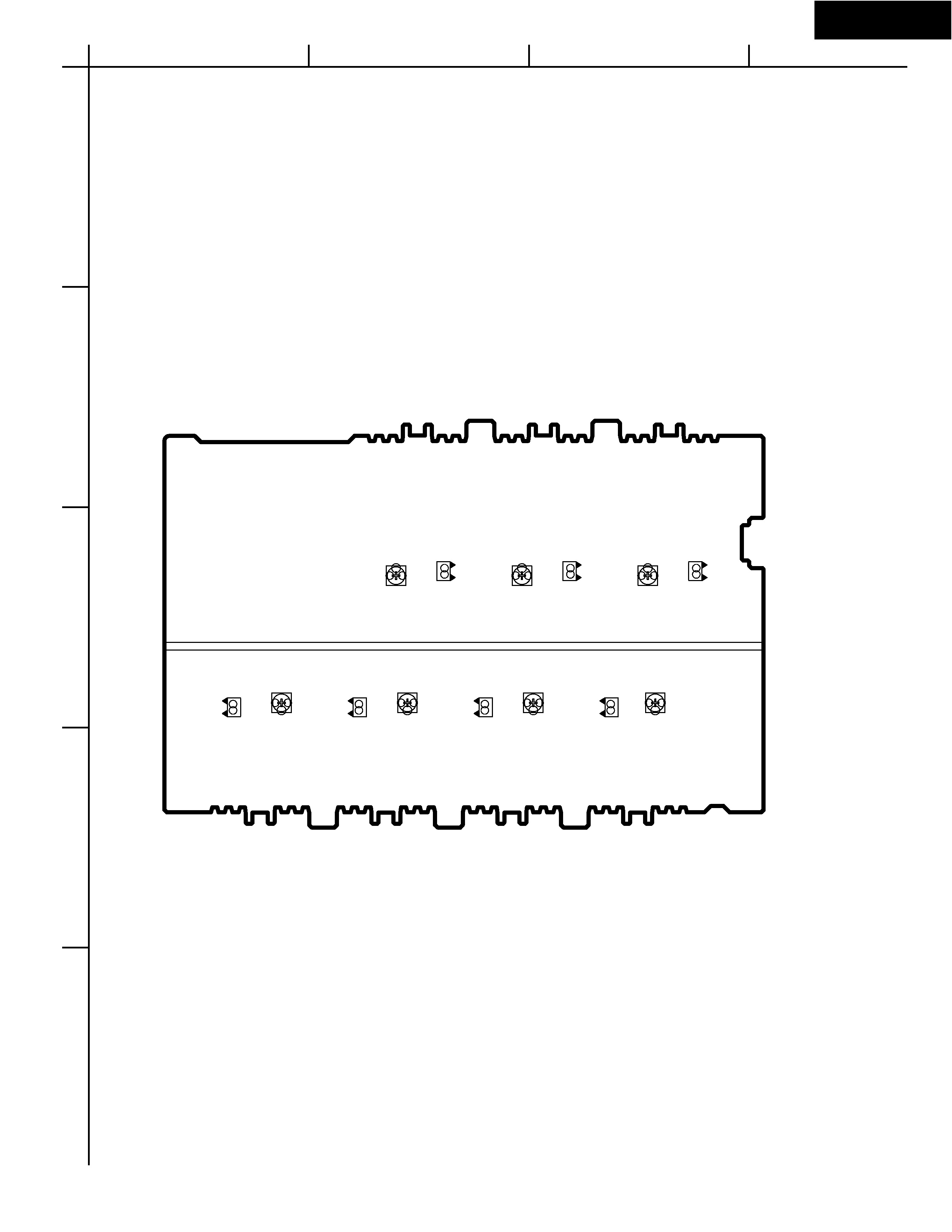
Idling current adjustment
Before Idling adjustment, turn the trimming resistors R6040 to R6046 to counter clockwise.
Connect the DC voltmeter to sockets P6080 to P6086.
After turn POWER to ON, adjust the trimming resistors R6040, R6041 and R6042 so that the reading of
voltmeter becomes 7.0 mV. (Front and center channels)
Adjust the trimming resistors R6043, R6044, R6045 and R6046 so that the reading of
After adjustment, attach the top cover.
voltmeter becomes 5.0 mV. (Surround and surround back channels)
Confirm the voltage of points above after about five minutes.
Front and center channels
When less than 9.0 mV, readjust the resistors above so that the voltage becomes 9.0 mV.
When 9.0 mV to 11.0 mV, you are not necessary to adjust.
When more than 11.0 mV, readjust the resistors above so that the voltage becomes 11.0 mV.
Surround and surround back channels
When less than 6.0 mV, readjust the resistors above so that the voltage becomes 6.0 mV.
When 6.0 mV to 8.0 mV, you are not necessary to adjust.
When more than 8.0 mV, readjust the resistors above so that the voltage becomes 8.0 mV.
Note: No load and No signal
L ch.
P6080
R6042 P6082
R6041 P6081
R6043
R6044
R6045
R6046
P6083
P6084
P6085
P6086
R ch.
C ch.
SR ch.
SL ch.
SBL ch.
SBR ch.
NAAF-7250
R6040
+ID
-ID
+ID
-ID
+ID
-ID
+ID
-ID
+ID
-ID
+ID
-ID
+ID
-ID
Confirmation of protection circuit
1. Confirmation of operation of speaker relay
Confirm that the speaker relays turn ON approximate. 5 seconds after the power switch is turned ON.
Confirm that the speaker relays turn OFF immediately after the power switch is turned OFF.
2. Confirmation of DC detection circuit
Press and hold down CD button, then press STANDBY/ON and DISPLAY buttons to set the unit to
"TEST-1" mode.
After "TEST-1" on the FL tube light on, press VIDEO 1 button to set the unit to "TEST-1-00".
Apply DC 1.5 to 3V to MULTI CHANNEL INPUT terminal with no load.
Confirm that the speaker relay turns OFF.
Apply DC -1.5 to -3V to MULTI CHANNEL INPUT terminal with no load.
Confirm that the speaker relay turns OFF.
Caution: Don't apply DC voltage more than 1 sec..
A
1
2
3
4
5
B
C
D
E
F
G
H
TX-DS898
ADJUSTMENT AND CONFIRMATION PROCEDURES
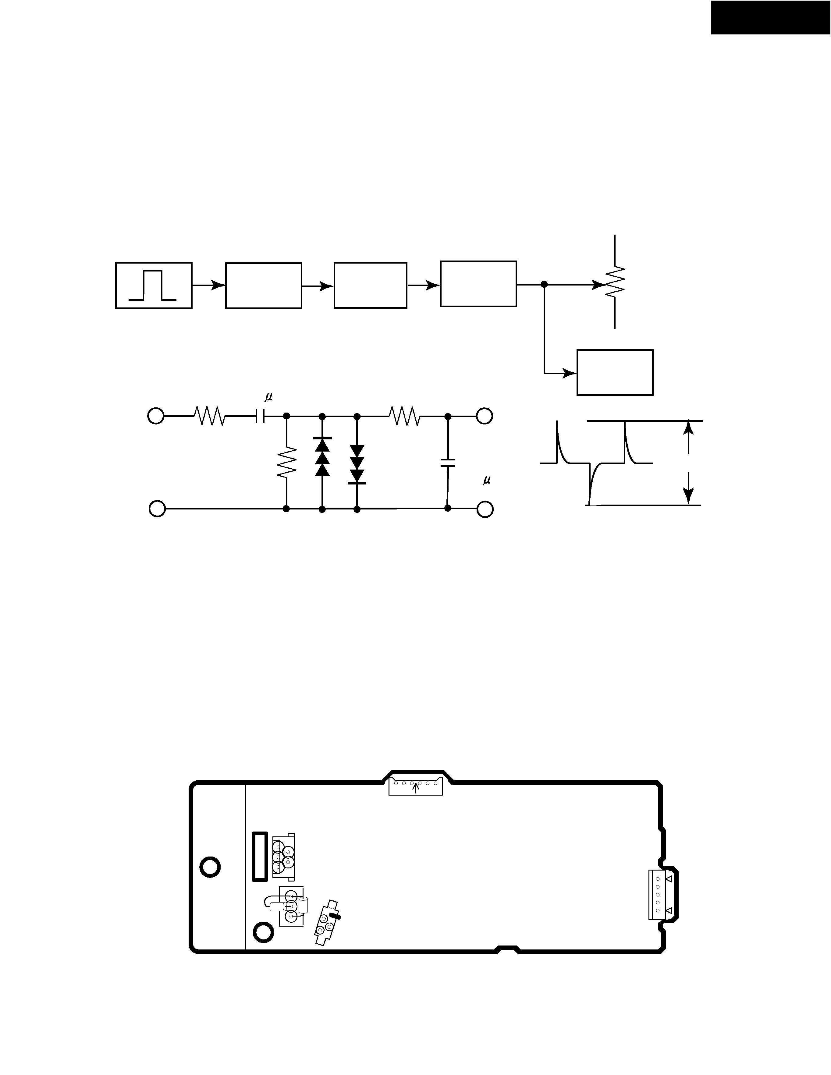
3. Confirmation of Current detection circuit
Set the unit to "TEST-1-00".
Connect the differentiating circuit and apply the 200Hz square signal to MULTI CHANNEL INPUT terminal.
of each channel.
Adjust the attenuator or Volume so that the output level becomes 35V p-p.
Confirm that the speaker relay does not turn OFF when a 3.0 ohm load is connected.
Confirm that the speaker relay turns OFF when a 1.5 ohm load is connected.
CR
OSCILLATOR
DIFFEREN-
TIATING
CIRCUIT
ATTENU-
ATOR
UNIT
SPEAKER
TERMINAL
MULTI
CHANNEL
INPUT
INPUT
OUT-
PUT
3.3k
10k
1SS133
3.3k
GND
0.01 F
0.1 F
OSCILLO-
SCOPE
Differentiating Circuit
200Hz
SQUARE
35Vp-p
Confirmation of fan
Set the unit to "TEST-1-00".
Apply the 1kHz -30dBV signal to the left channel of MULTI-CH terminal with no load.
Confirm that the fan rotates slow speed after few seconds.
Connect the 1.2 kohm/1W resistor between terminals COM and TH-1 of P6401 with no input signal.
Confirm that the fan rotates slow speed after few seconds.
Next apply the 1kHz -30dBV signal to the left channel of MULTI-CH terminal with no load.
Confirm that the fan rotates high speed after few seconds.
Connect the 1.2 kohm/1W resistors between terminals COM-TH-1 and COM-TH-2 of P6401 respectively with no input signal.
Confirm that the fan rotates high speed after few seconds.
P
69
31
P
77
01
B
P9503A
JL
69
33
A
P
64
01
COM
TH1
TH2
NAETC-7238
TX-DS898
ADJUSTMENT AND CONFIRMATION PROCEDURES 3
Test Mode
1. Turn POWER button on.
2. Press and hold down CD button, then press DISPLAY and STANDBY/ON buttons.
3. After "TEST-1" on the FL tube is displayed, press CD button to set the unit to the test mode of FL tube.
Note: VIDEO 1:TEST-1 VIDEO 2 :TEST-2 ZONE2: UP
VIDEO 3 :TEST-3 VIDEO 4:TEST-4 REC OUT: DOWN
Test-X YZ
Item
FL TUBE
The segments of even
number light on .
All segments
light on.
"FEDCBA987654321"
light on.
"AA BB CC DD EE"
light on.
Test mode of FL tube
REC OUT
ZONE 2
Press POWER button
to finish the test mode of FL tube.
AA:Model "89":TX-DS898 "79":TX-DS797
BB:Video Mode "NS": NTSC "PL": PAL AUTO
CC:12V TRIGGER "TR": Available " ":No available
DD:RDS "RD": Available " ":No available
The segments of odd
number light on .
Confirmation of voltage sensor
1. Set the unit to TEST-3-4.
2. Apply the signal 1kHz, -15dBV to the MULTI-CH
input. Confirm that the FM STEREO is displayed.
Confirm the all channels except SUBWOFFER.
3. When connect the resistor 1.2 kohm/1 W between
the terminals COM and TH1 of P6401, confirm that
"MEMORY" light on.
Note: No input signal.
4.When change set the unit to "TEST-4-39,confirm
that the speaker relays of RL6901 and RL6902
turn off.
Note: No input signal.
EE:Tuner band EU:Europe US: USA SA:Worldwide JP:Japan