FM STEREO/AM TUNER
AMPLIFIER
MODEL R-805TX
Silver model
230-240V AC, 50Hz
120 V AC, 60 Hz
SUPP, SUPT
SUDT
SAFETY-RELATED COMPONENT WARNING!!
COMPONENTS IDENTIFIED BY MARK
ON THE
SCHEMATIC DIAGRAM AND IN THE PARTS LIST
ARE CRITICAL FOR RISK OF FIRE AND ELEC-
TRIC SHOCK. REPLACE THESE COMPONENTS
WITH ONKYO PARTS WHOSE PARTS NUMBERS
APPEAR AS SHOWN IN THIS MANUAL.
MAKE LEAKAGE-CURRENT OR RESISTANCE
MEASUREMENTS TO DETERMINE THAT EXPO-
SED PARTS ARE ACCEPTABLY INSULATED FORM
THE SUPPLY CIRCUIT BEFORE RETURNING THE
APPLIANCE TO THE CUSTOMER.
Ref. No. 3681
052001
R-805TX
SERVICE MANUAL
STANDBY / ON
DISPLAY
PHONES
MEMORY
CLEAR
FM MODE
PRESET
TUNING
R-805TX
FM STEREO / AM TUNER AMPLIFIER
ENERGY SAVE
ACOUSTIC
PRESENCE
OFF / 1 /2/3
CD
MD
CDR/PC
LINE/DVD
FM
AM
TAPE
INPUT
VOLUME
WIDE RANGE AMPLIFIER
TECHNOLOGY
WIDE RANGE AMPLIFIER
TECHNOLOGY
ACCUCLOCK
STANDBY / ON
DISPLAY
PHONES
MEMORY
CLEAR
FM MODE
PRESET
TUNING
R-805TX
FM STEREO / AM TUNER AMPLIFIER
ENERGY SAVE
ACOUSTIC
PRESENCE
OFF / 1 /2/3
CD
MD
CDR
LINE/DVD
FM
AM
TAPE
INPUT
VOLUME
Asian model
European model

SPECIFICATIONS
Fr
T
Amplier Section
Power output
20 watts per channel, min RMS, at 4
ohms, both channels driven 1 kHz,
with no mor e than 0.6% THD
15 watt per channel, min RMS, at
8 ohms, both channels driven 1 kHz,
with no mor e than 0.6% THD
2 X 20 watts at 4 ohms, 1 kHz, DIN
2 X 17 watts at 6 ohms, 1 kHz, DIN
2 X 15 watts at 8 ohms, 1 kHz, DIN
2 X 29 watts at 4 ohms, 1 kHz, EIAJ
Dynamic power output
2 X 24 watts at 4 ohms
2 X 17 watts at 8 ohms
otal harmonic distortion
0.6% at rated power
IM distortion
0.6% at rated power
Damping factor
30 at 8 ohms
Input Sensitivity and Impedance
TAPE/MD PLAY: 150 mV, 50 kohms
LINE IN: 150 mV, 50 kohms
equency and r esponse
10 to 50,000 Hz +0 / 3 dB
one contr ol
ACOUSTIC PRESENCE 1
+4 dB at 82 Hz
ACOUSTIC PRESENCE 2
+3 dB at 20.5 Hz, + 3 dB at 82 Hz
ACOUSTIC PRESENCE 3
+3 dB at 20.5 Hz, + 6 dB at 82 Hz
BASS
±8 dB at 100 Hz
TREBLE
±8 dB at 10 kHz
Signal to noise ratio
TAPE: 100 dB (IHF-A)
Muting
dB
Tuner Section
Tuning range
FM: 87.9 to 107.9 MHz (200 kHz steps)
(U.S. & Canadian models)
87.5 to 108.00 MHz (50 kHz steps)
(Other area models)
AM: 530 to 1710 kHz (10 kHz steps)
(U.S. & Canadian models)
522 to 1611 kHz (9 kHz steps)
(Other area models)
Usable sensitivity
FM: Mono 11.2 dBf,
1.0 µV (75 ohms IHF)
0.9 µV (75 ohms DIN)
Stereo 17.2 dBf,
2.0 µV (75 ohms IHF)
23.0 µV (75 ohms DIN)
AM: 30 µV
50 dB Quieting sensitivity
FM: Mono 17.2 dBf, 2.0 µV (75 ohms)
Stereo 37.2 dBf, 20.0 µV (75 ohms)
Captur e ratio
FM: 2.0 dB
Image r ejection ratio
FM: 40 dB (U.S. & Canadian models)
85 dB (Other area models)
AM: 40 dB
IF rejection ratio
FM: 90 dB
AM: 40 dB
Signal to noise ratio
FM: Mono 73 dB, IHF
Stereo 67 dB, IHF
AM: 40 dB
Selectivity
FM: 50 dB DIN
(±300 kHz at 40 kHz Devi.)
AM Suppr ession Ratio
50 dB
Harmonic distortion
FM: Mono 0.2%
Stereo 0.3%
AM: 0.7 %
Frequency r esponse
FM: 30 to 15,000 Hz (±1.5 dB)
Stereo separation
FM: 45 dB at 1,000 Hz
30 dB at 100 to 10,000 Hz
Stereo thr eshold
FM: 17.2 dBf, 2.0 µV (75 ohms)
General
Clock precision
monthly error: +/-30 seconds
(at 25 degrees Celsius)
Power supply
AC 120 V, 60 Hz
AC 230 V, 50 Hz
Power consumption
61 W (120 V, 50 Hz)
54 W (230 V, 60 Hz)
Dimensions (W X H X D)
205 X 91 X 302 mm
8-1/16" X 3-9/16" X 11-7/8"
Weight
3.4 kg, 7.5 lbs
Specications and external appearance are
subject to change without notice as a result
of product improvement.
R-805TX

5. Changing the AM band step
The tuning step selector switch is not provided in this model.
When you change the band step, change the parts as shown
below.
To 10kHz
To 9kHz
R715
3.3k
10k
R716
5.6k
Open
6. Adjustment of clock frequency
1. Connect the frequency counter to the terminal TP701.
2. Press and hold down the MEMORY button, then press the
DISPLAY button.(All segments on FL tube light on)
3. Adjust the trimmer capacitor C707 so that the reading of
frequency counter becomes 524.288 kHz+/-1Hz.
4. Memory Preservation
This unit does not require memory preservation batteries. A
built-in memory power back-up system preserves the contents
of the memory during po wer f ailures and ev en when the unit is
unplugged.The unit must be plugged in order to char ge the
back-up system.
The memory preserv ation period after the unit has been
unplugged varies depending on climate and placement of the
unit. On the a v erage, memory contents are protected ov er a
period of a fe w weeks after the last time the unit has been
unplugged. This period is shorter when the unit is exposed to a
highly humid climate.
2. To initialize the unit
This device employs a microprocessor to perform various
functions and operations. If interference generated by an external
power supply, radio wave, or other electrical source results in
accident which causes the specified operations and functions to
operate abnormally.
To perform a result, please follow the procedure below.
1. Press and hold down the MEMORY button, then press the
DISPLAY button.
2. Press the STANDBY/ON button.
After "clear" is displayed, the preset memory and each
mode stored in the memory, such as surround, are
initialized and will return to the factory setting.
3. Safety-check out
(120V model only)
After correcting the original service problem, perform the
following safety check before releasing the set to the customer.
Connect the insulating-resistance tester between the plug of power
supply cord and screw on the back panel.
Specifications: 3.3Mohm+/-10% at 500V.
1. Replacing the fuses
This symbol located near the fuses indicates that the
fuse used is fast operating type. For continued protection against
fire hazard, replace with same type fuse. For fuse rating refer to
the marking adjacent to the symbol.
Ce symbole indique que le fusible utlise est a rapide.
Pour une protection permanente, n'untiliser que fusibles de
meme type. Ce darnier est la qu le present symbol est
appse.
CIRCUIT NO.
PART NO.
DESCRIPTION
F901
F902
252158
252083
252069
Note: <D>: 120V model only
<P/T>: 230V model only
1.6A-UL/T237, Primary <D>
0.4A-SE-EAWK, Primary
<P/T>
0.8A-SE-EAK,AC outlet
<P/T>
SERVICE PROCEDURES
R-805TX
STANDBY/ON button
Input source indicators
Multi display
Timer setting
Frequency
indicators
MUTING indicator
indicators
Sleep time indicator
STEREO
MUTING
MIN
kHz
MHz
MONO
PM
RDS
AM
AUTO
TIMER
W.DAY
W.END
REC
SLEEP
MEMORY
WIDE RANGE AMPLIFIER
TECHNOLOGY
ACCUCLOCK
STANDBY / ON
DISPLAY
PHONES
MEMORY
CLEAR
FM MODE
PRESET
TUNING
R-805TX
FM STEREO / AM TUNER AMPLIFIER
ENERGY SAVE
ACOUSTIC
PRESENCE
OFF / 1 / 2 / 3
CD
MD
CDR
LINE/DVD
FM
AM
TAPE
INPUT
VOLUME
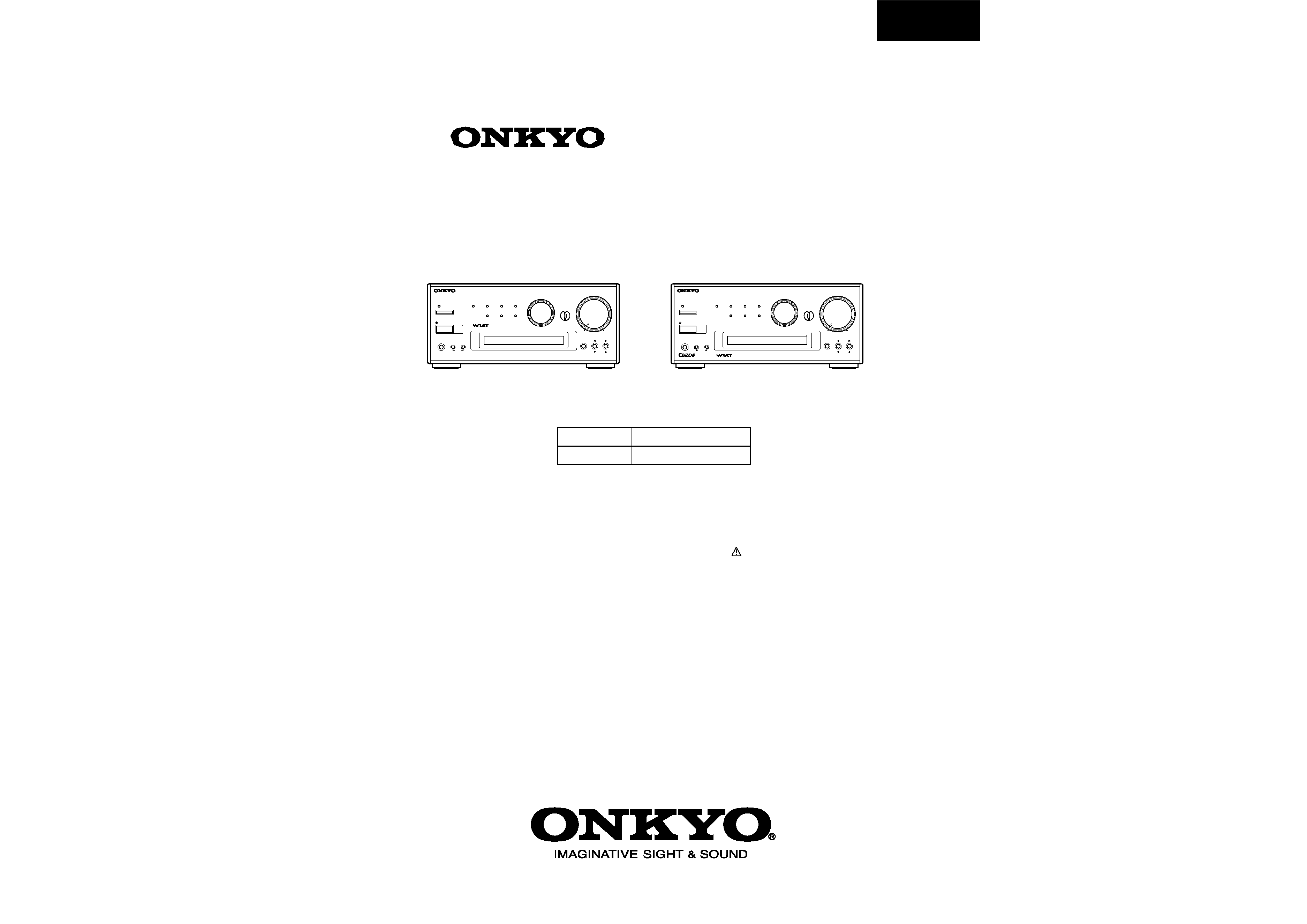
Remote control sensor
INPUT selector
VOLUME control
PHONES jack
ACOUSTIC PRESENCE button
ENERGY SA VE indicator
PRESET
buttons
TUNING
buttons
DISPLAY button
MEMORY button
CLEAR or
FM MODE button
ENERGY SA VE button
Display
AUTO/MONO indicator
MEMORY indicator
Tuning indicator
STEREO indicator
AM/PM indicator
RDS indicator
(non-U.S., non-Canadian models only)
European models front panel shown.
PANEL VIEWS
FRONT PANEL
REAR PANEL
L
R
SPEAKERS
OUT
IN
L
R
OUT
MD
CDR
TAPE
CD
IN
LINE/DVD
PROCESSOR
OUT
IN
OUT
IN
REMOTE
CONTROL
L
R
L
R
L
R
AM
FM
75
ANTENNA
CAUTION:
SPEAKER
IMPEDANCE
4 OHMS MIN.
/SPEAKER
AC OUTLET
AC 230-240V
50Hz
SWITCHED
100W MAX.
(PLAY)
(REC)
(PLAY)
(REC)
OUT
IN
L
R
(REC)
(PLAY)
OUT
MD
CDR
TAPE
CD
IN
LINE/DVD
PROCESSOR
OUT
IN
OUT
IN
REMOTE
CONTROL
L
R
L
R
L
R
CD recorder
Stereo cassette
tape deck
PLAY
OUTPUT
REC
INPUT
PLAY
OUTPUT
REC
INPUT
PLAY
OUTPUT
REC
INPUT
AUDIO
OUTPUT
: Signal flow
This unit (R-805TX)
(illustration is European model)
CD player
MD recorder
DVD, LD or Video equipment
OUTPUT
For the Asian model:
In addition to a CD
recorder , you can
connect a digital
audio processor to
this connector .
Connecting a sound processor (other than U.S. & Canadian models)
-
.
Connections
1 Remove the jumper plugs.
2 Connect the sound processor to the unit.
OUT
IN
PRO
CES
SOR
Jumper plug
L
R
SPEAKERS
OUT
IN
L
R
OUT
MD
CDR
TAPE
CD
IN
LINE/DVD
PROCESSOR
OUT
IN
OUT
IN
REMOTE
CONTROL
L
R
L
R
L
R
AM
FM
75
ANTENNA
CAUTION:
SPEAKER
IMPEDANCE
4 OHMS MIN.
/SPEAKER
AC OUTLET
AC 230-240V
50Hz
SWITCHED
100W MAX.
OUT
IN
PROCESSOR
L
R
OUTPUT
: Signal flow
This unit (R-805TX)
INPUT
Sound processor
R-805TX
·
You can control the other
-connected components with the supplied remote controller.
·
The remote controller buttons operate in the same way as the buttons on each component
with the same indication.
·
For actual operations, please refer to the Instruction Manual for each component.
CLOCK
SLEEP
EFFECT
GRAPHIC EQ
MODE
1
2
3
4
5
6
7
8
9
10/0
--/---
VOLUME
PRESET
FM
AM
PLAY MODE
PLAY MODE
REPEAT
CLEAR
SCROLL
MEMORY
REPEAT
CLEAR
DISC
REPEAT
CLEAR
ACOUSTIC
PRESENCE
TONE
RANDOM
TIMER
UP/DOWN
ENTER
MUTING
INPUT
TUNER
M D
DVD
C D
CDR
TAPE
REC
REC
PAUSE/STEP
STANDBY/ ON
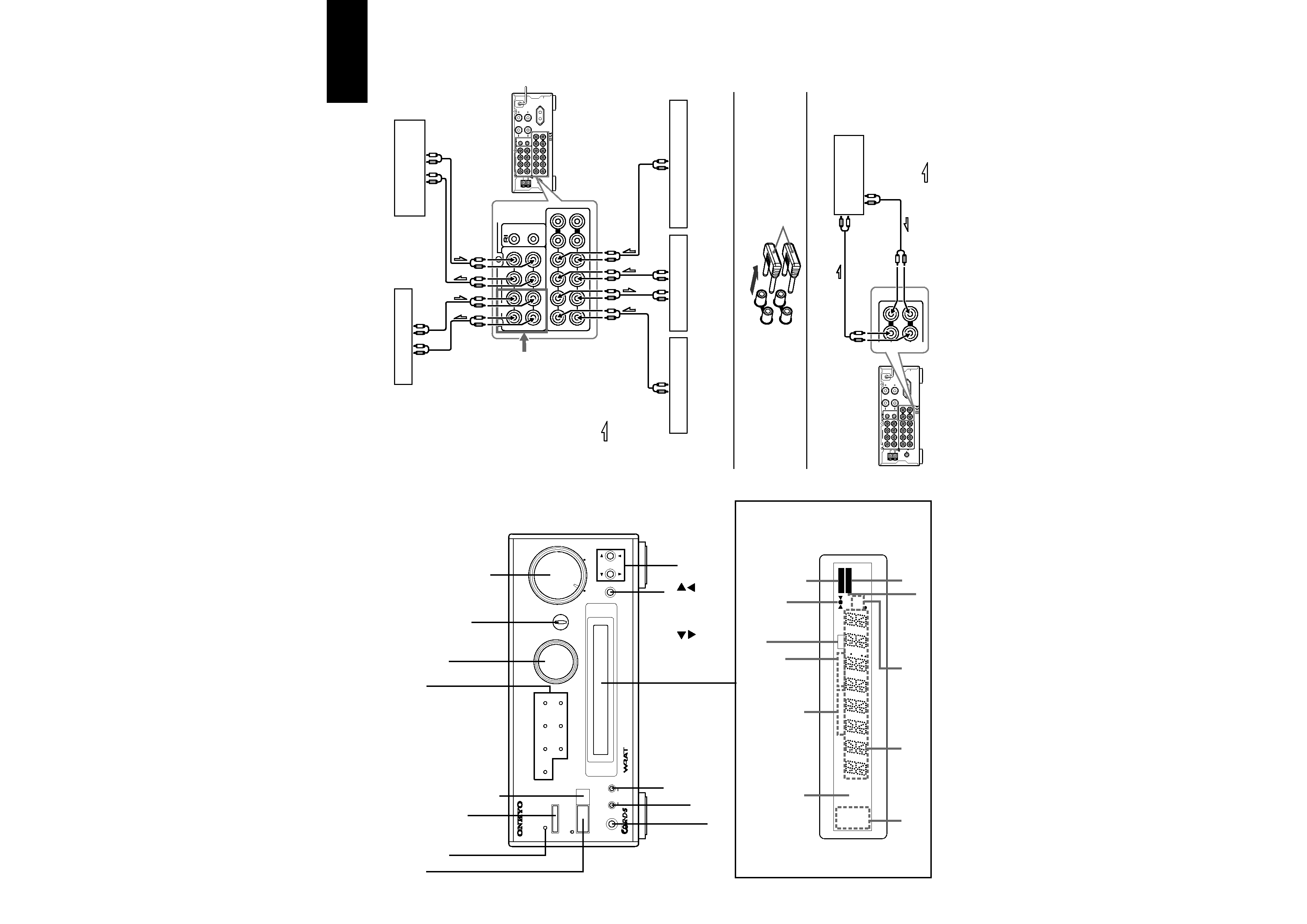
REMOTE CONTROLLER
RC-
456S
CLOCK button
Press this button to
display the current
time.
SLEEP button
Enables you to
make the Sleep
time setting.
INPUT button
Enables you to
select a listening
source.
MUTING button
Mutes the sound
temporarily .
VOLUME
/
but-
tons
Enables you to
increase or decrease
the volume level.
ACOUSTIC PRES-
ENCE button
Switches acoustic
presence of f and
types.
Number buttons
Used to set the
time/day and select
the PRESET stations.
STANDBY/ON button
Toggles between STANDBY and
ON.
Tuner control
PRESET
: Tuner preset select
buttons
FM : FM band select button
AM : AM band select button
Enables you to set the tone.
TIMER:
Pressing this button
repeatedly to select one of the
following eight settings.
WEEKDAY: Timer playback on
the specified day(s) of the week.
WEEKEND:Timer playback on
the specied day(s) of the week.
REC:Timer record setting
DAYSET:Sets the day of the
week (WEEKDAY & WEEKEND).
ADJUST:Sets the current time
and the day of the week.
24H/12H: Enables you to select
24-hour display or 12-hour dis-
play by pressing the ENTER but-
ton and using the UP
/DOWN
buttons.
UP
/DOWN
: Enables you to
select a parameter after you
press the TIMER or TONE but-
ton. Press the ENTER button to
confirm the selection.
ENTER:Press this button to con-
firm the selection made via the
TIMER, TONE, UP
, or
DOWN
button.
·
Use the following buttons to control components that are connected to the
- system.
CLOCK
SLEEP
EFFECT
GRAPHIC EQ
MODE
1
2
3
4
5
6
7
8
9
10/0
--/---
VOLUME
PRESET
FM
AM
PLAY MODE
PLAY MODE
REPEAT
CLEAR
SCROLL
MEMORY
REPEAT
CLEAR
DISC
REPEAT
CLEAR
ACOUSTIC
PRESENCE
TONE
RANDOM
TIMER
UP/DOWN
ENTER
MUTING
INPUT
TUNER
M D
DVD
C D
CDR
TAPE
REC
REC
PAUSE/STEP
STANDBY/ ON
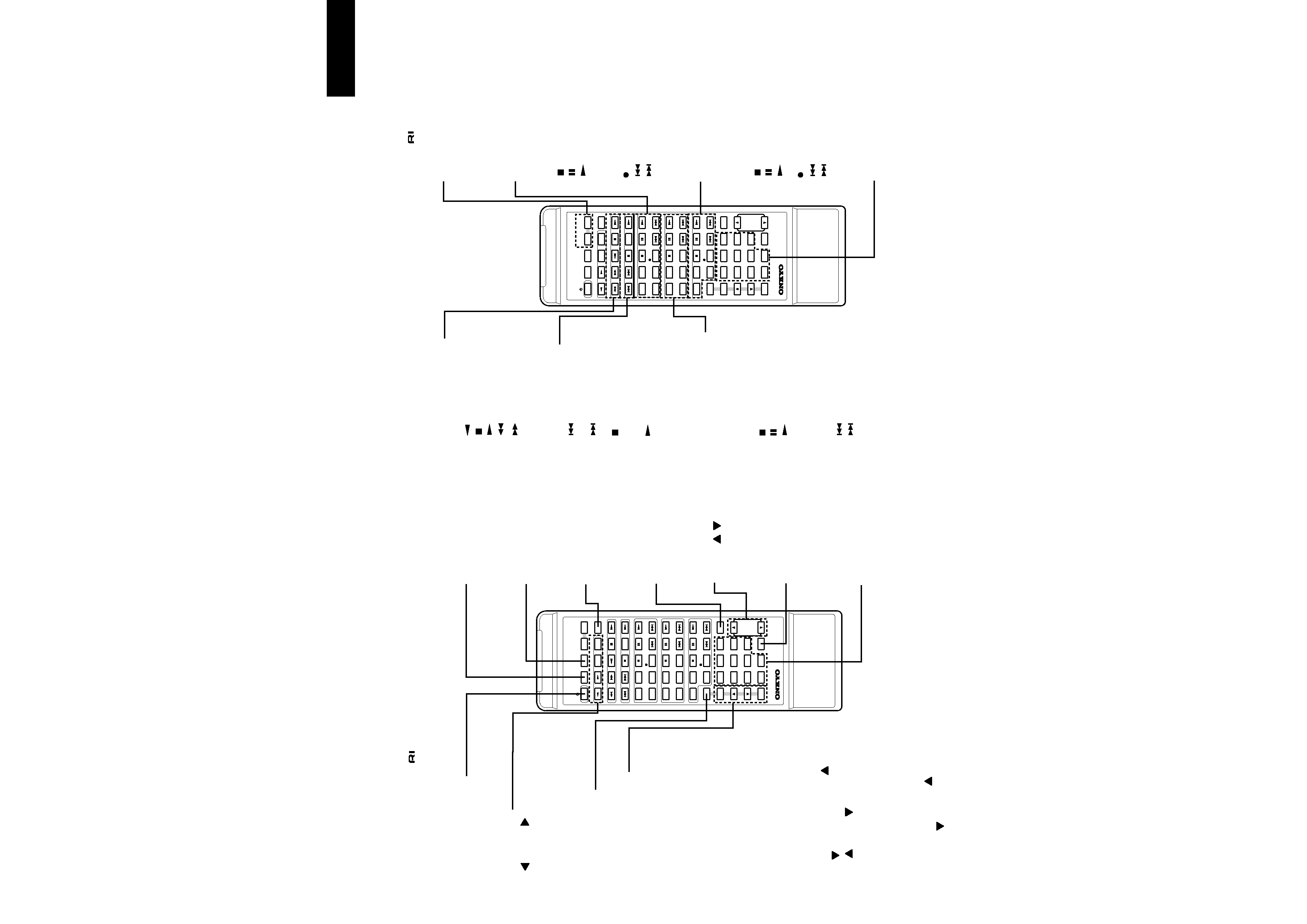
REMOTE CONTROLLER
RC-
456S
Graphic equalizer con-
tr ol
EFFECT: Ef fect select button
MODE: Mode select button
MD recorder control
REPEAT : Repeat mode
button
SCROLL : Scroll button
: Stop button
: Pause button
: Play button
PLAY MODE:Play mode
selection button
CLEAR:Clear button
REC:Recording button
: Track down button
: Track up button
CD recorder contr ol
REPEAT : Repeat mode
button
PLAY MODE : Play mode
selection button
: Stop button
: Pause button
: Play button
CLEAR:Clear button
REC:Recording button
: Track down button
: Track up button
CD player (or changer) /
MD r ecorder /
CD recorder control
1~9, 10/0 : Number buttons
--/---
: Ten's hold button
Stereo cassette tape
deck control
: Reverse play button
: Stop button
: Play button
: Rewind button
: Fast-forward button
DVD player control
: Chapter/track down
button
: Chapter/track up
button
: Stop button
PAUSE/STEP : Pause/Step
forward button
: Play button
CD player (or changer)
control
REPEAT : Repeat mode button
RANDOM :Random play
button
: Stop button
: Pause button
: Play button
MEMORY:Memory button
CLEAR : Clear button
DISC : Disc button for CD
changer
: Track down button
: Track up button
REMOTE CONTROLLER
R-805TX
Mode Select buttons
TONE button