R-801A
SAFETY-RELATED COMPONENT
WARNING!!
COMPONENTS IDENTIFIED BY MARK
ON THE
SCHEMATIC DIAGRAM AND IN THE PARTS LIST ARE
CRITICAL FOR RISK OF FIRE AND ELECTRIC SHOCK.
REPLACE THESE COMPONENTS WITH ONKYO
PARTS WHOSE PART NUMBERS APPEAR AS SHOWN
IN THIS MANUAL.
MAKE LEAKAGE-CURRENT OR RESISTANCE
MEASUREMENTS TO DETERMINE THAT EXPOSED
PARTS ARE ACCEPTABLY INSULATED FROM THE
SUPPLY CIRCUIT BEFORE RETURNING THE
APPLIANCE TO THE CUSTOMER.
SERVICE MANUAL
SERVICE MANUAL
FM STEREO/AM TUNER AMPLIFIER
MODEL
R-801A
Ref. No. 3719
102001
230-240V AC, 50Hz
120V AC, 50/60Hz
220-230V,50/60Hz
MPP
MDT
MGT,MGR
DISPLAY
R-
801A
STANDBY / ON
STANDBY
INPUT
ACOUSTIC
PRESENCE
TUNING
MEMORY
FM MODE
CLEAR
PHONES
TUNER AMPLIFIER
VOLUME
European models front panel shown.

R-801A
SPECIFICATIONS
Amplifier Section
Power output
17 watts per channel, min RMS, at 4
ohms, both channels driven 1 kHz,
with no more than 0.8% THD
13 watt per channel, min RMS, at
8 ohms, both channels driven 1 kHz,
with no mor e than 0.8% THD
2 X 17 watts at 4 ohms, 1 kHz, DIN
2 X 15 watts at 6 ohms, 1 kHz, DIN
2 X 13 watts at 8 ohms, 1 kHz, DIN
2 X 24 watts at 4 ohms, 1 kHz, EIAJ
Dynamic power output
2 X 21 watts at 4 ohms
2 X 14 watts at 8 ohms
Total harmonic distortion
0.8% at rated power
IM distortion
0.8% at rated power
Damping factor
20 at 8 ohms
Input Sensitivity and Impedance
TAPE, MD, CD/DVD, CDR/PC:
150 mV, 50 kohms
Frequency and response
10 to 100 kHz ±3 dB
Tone control
ACOUSTIC PRESENCE 1
+4.5 dB at 41 Hz
ACOUSTIC PRESENCE 2
+5.5 dB at 82 Hz
ACOUSTIC PRESENCE 3
+6 dB at 41 Hz, + 6 dB at 82 Hz
ACOUSTIC PRESENCE 4
+6 dB at 41 Hz, + 6 dB at 82 Hz,
+5 dB at 10 Hz
Signal to noise ratio
TAPE: 100 dB (IHF-A)
Muting
50 dB
Tuner Section
Tuning range
FM: 87.9 to 107.9 MHz (200 kHz steps)
(U.S. & Canadian models)
87.5 to 108.00 MHz (50 kHz steps)
(Other area models)
AM: 530 to 1710 kHz (10 kHz steps)
(U.S. & Canadian models)
522 to 1611 kHz (9 kHz steps)
(Other area models)
Usable sensitivity
FM: Mono 11.2 dBf,
1.0 µV (75 ohms IHF)
0.9 µV (75 ohms DIN)
Stereo 17.2 dBf,
2.0 µV (75 ohms IHF)
23.0 µV (75 ohms DIN)
AM: 30 µV
50 dB Quieting sensitivity
FM: Mono 17.2 dBf, 2.0 µV (75 ohms)
Stereo 37.2 dBf, 20.0 µV (75 ohms)
Captur e ratio
FM: 2.0 dB
Image r ejection ratio
FM: 40 dB (U.S. & Canadian models)
85 dB (Other area models)
AM: 40 dB
IF rejection ratio
FM: 90 dB
AM: 40 dB
Signal to noise ratio
FM: Mono 73 dB, IHF
Stereo 67 dB, IHF
AM: 40 dB
Selectivity
FM: 50 dB DIN
(±300 kHz at 40 kHz Devi.)
AM Suppr ession Ratio
50 dB
Harmonic distortion
FM: Mono 0.2%
Stereo 0.3%
AM: 0.7 %
Frequency response
FM: 30 to 15,000 Hz (±1.5 dB)
Stereo separation
FM: 45 dB at 1,000 Hz
30 dB at 100 to 10,000 Hz
Stereo threshold
FM: 17.2 dBf, 2.0 µV (75 ohms)
General
Clock precision
monthly error: +/-30 seconds
(at 25 degrees Celsius)
Power supply
AC 120 V, 60 Hz
AC 230-240 V, 50 Hz
AC 220-230 V, 50 Hz/60 Hz
Power consumption
44 W
Dimensions (W X H X D)
155 X 94 X 285 mm
6-1/8" X 3-1/16" X 11-1/4"
Weight
2.9 kg, 6.4 lbs
Specifications and external appearance are
subject to change without notice as a result
of product improvement.
R-801A
SERVICE PROCEDURES
4. Memory Preservation
This unit does not require memory preservation batteries. A
built-in memory power back-up system preserves the contents
of the memory during po wer f ailures and ev en when the unit is
unplugged.The unit must be plugged in order to char ge the
back-up system.
The memory preserv ation period after the unit has been
unplugged varies depending on climate and placement of the
unit. On the a v erage, memory contents are protected ov er a
period of a fe w weeks after the last time the unit has been
unplugged. This period is shorter when the unit is exposed to a
highly humid climate.
2. To initialize the unit
This device employs a microprocessor to perform various
functions and operations. If interference generated by an external
power supply, radio wave, or other electrical source results in
accident which causes the specified operations and functions to
operate abnormally.
To perform a result, please follow the procedure below.
1. Press and hold down the MEMORY button, then press the
DISPLAY button.
2. Press the STANDBY/ON button.
After "clear" is displayed, the preset memory and each
mode stored in the memory, such as surround, are
initialized and will return to the factory setting.
3. Safety-check out
(120V model only)
After correcting the original service problem, perform the
following safety check before releasing the set to the customer.
Connect the insulating-resistance tester between the plug of power
supply cord and screw on the back panel.
Specifications: 3.3Mohm+/-10% at 500V.
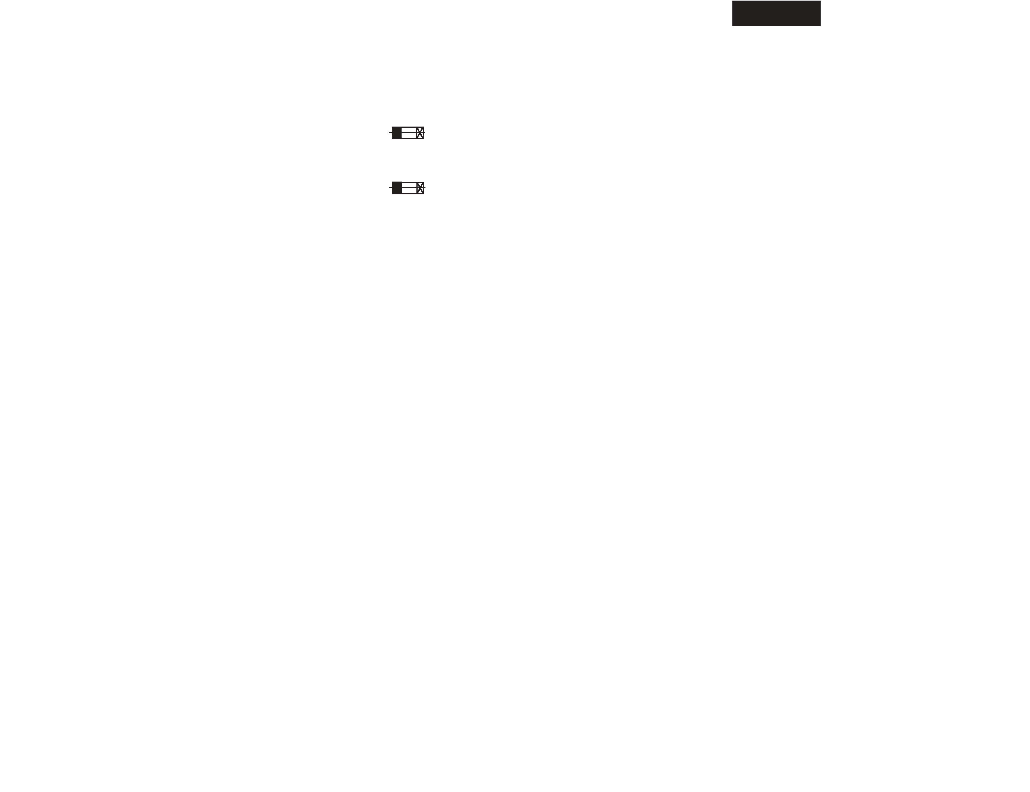
1. Replacing the fuses
This symbol located near the fuses indicates that the
fuse used is fast operating type. For continued protection against
fire hazard, replace with same type fuse. For fuse rating refer to
the marking adjacent to the symbol.
Ce symbole indique que le fusible utlise est a rapide.
Pour une protection permanente, n'untiliser que fusibles de
meme type. Ce darnier est la qu le present symbol est
appse.
CIRCUIT NO.
PART NO.
DESCRIPTION
F901
252082 or
252232 or
252266
252156 or
Note: <PP>: 230-240V model only
<DT>: 220V model only
<GT>: 120V model only
<GR>: 220-230V model only
0.315A-EAWK,Fuse <PP,GT,GR>
315MA-SE-TL250V,Fuse
315MA-SE-TL350V,Fuse
1A-UL/T-237,Fuse<DT>
252250
1A-T/UL-ST2,Fuse
R-801A
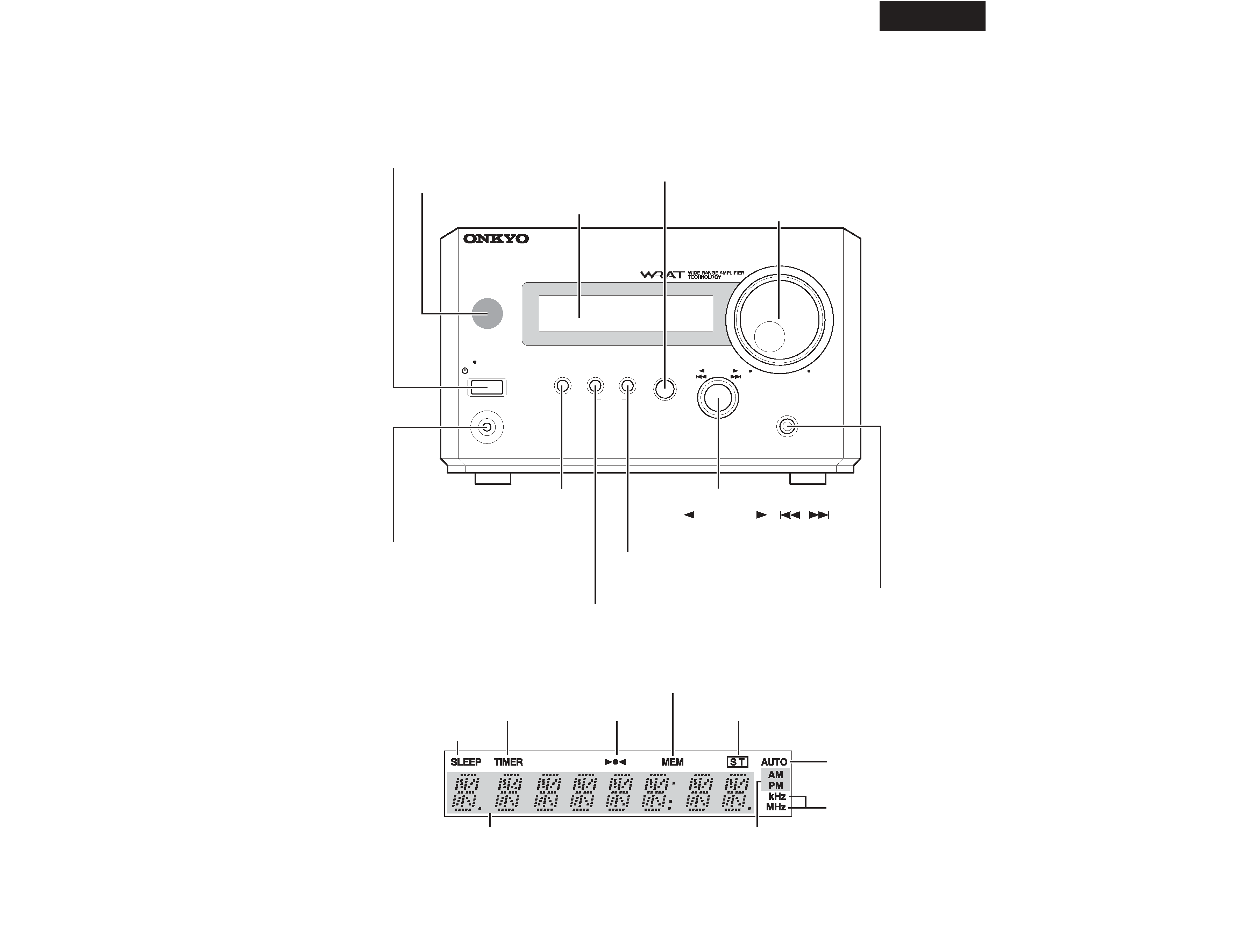
PANEL VIEW
FRONT PANEL
DISPLAY
R-
801A
STANDBY / ON
STANDBY
INPUT
ACOUSTIC
PRESENCE
TUNING
MEMORY
FM MODE
CLEAR
PHONES
TUNER AMPLIFIER
VOLUME
PHONES jack
Display
,
Display section
STANDBY/ON button
Remote control sensor
INPUT select button
VOLUME control
DISPLAY button
MEMORY button
FM MODE button
TUNING control
ACOUSTIC PRESENCE button
TIMER setting indicator
SLEEP timer indicator
Tuning indicator
MEMORY indicator
Multi display
STEREO indicator
AM/PM indicator
AUTO indicator
Frequency
indicator
(
TUNING
/
)
R-801A
A1
A2
A3
A4
A5
A6
A7
A8
A10
A11
A12
A13
A14
A15
A16
A17
S1
S2
S3
S4
E901
F901
P105
P701
P901
P961
P962
P963
Q511
Q512
Q611
Q612
U10
U1
U2
U3
U4
U5
U6
U7
U8
U9
A5
P961
S5
S6
S5
S5
S1
S1
S1
S1
S1
S4
S1
S1
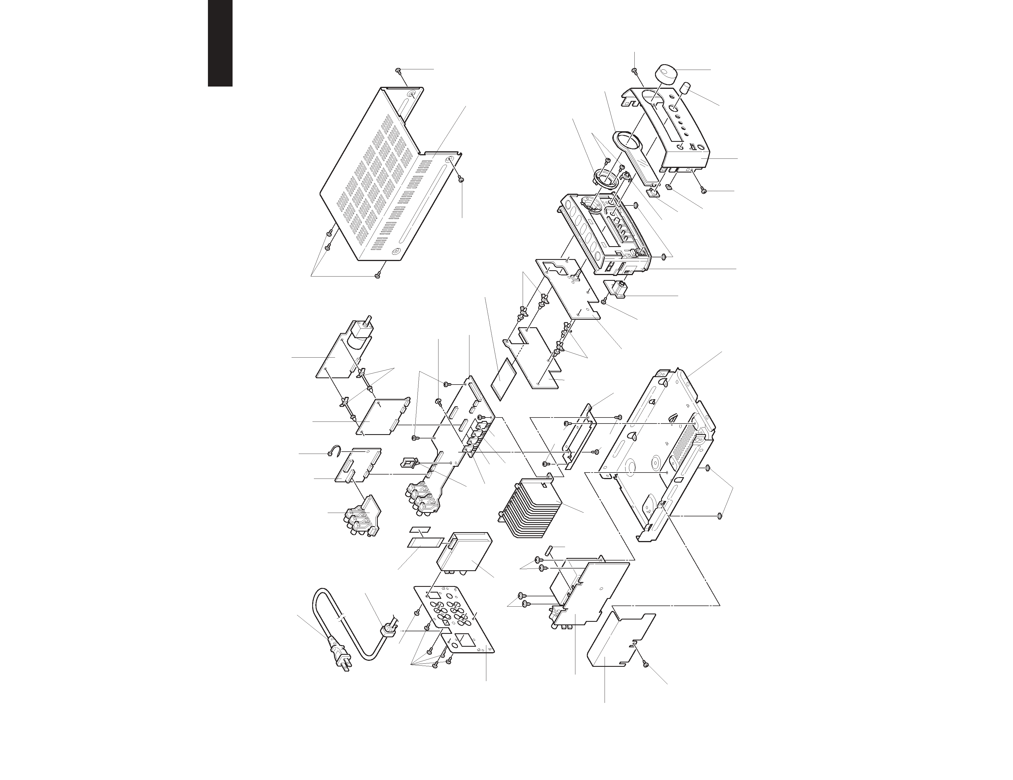
EXPLODED VIEW