NC-500
SERVICE MANUAL
SERVICE MANUAL
Audio Network Receiver
Silver model only
MODEL
NC-500
120V AC, 60Hz
TUDD
Ref. No. 3751
112002
AUDIO NETWORK RECEIVER
NC-
500
STANDBY / ON
VOLUME
AUDIO
INPUT
DISPLAY
PHONES
SELECT
SETUP
STANDBY
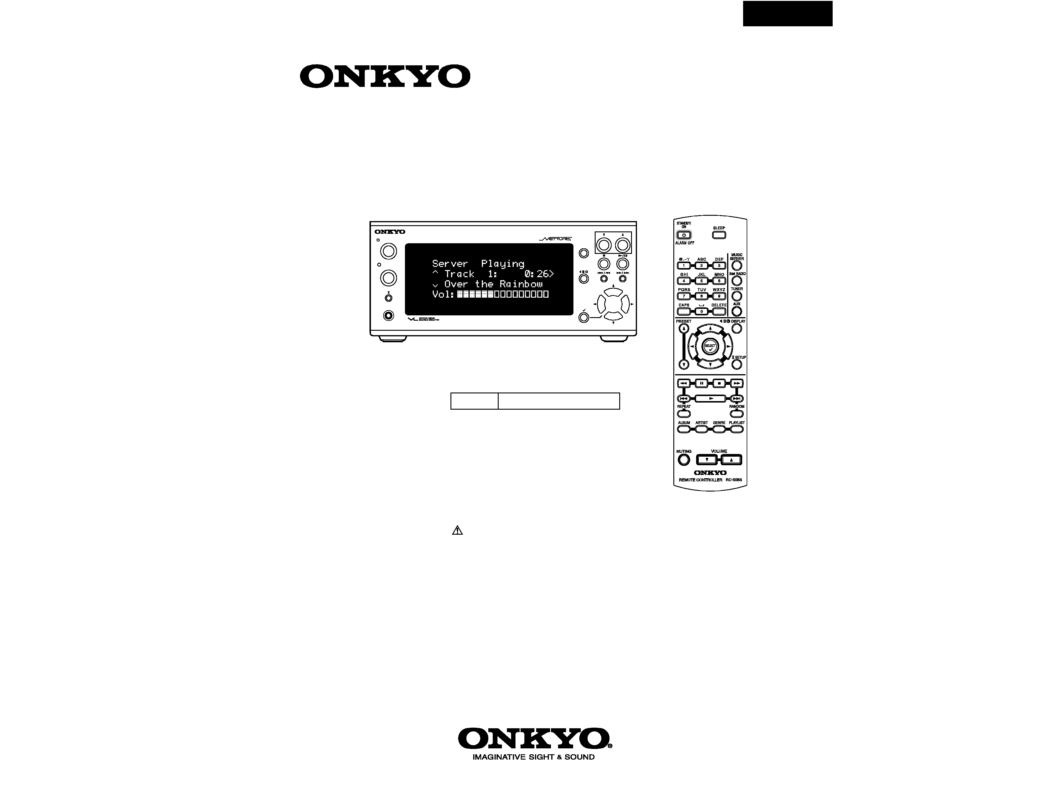
Restoring the factory default settings:
To reset all the stored settings to the factory
default conditions, while the power to the NC-500
is on, press and hold down the STOP button on
the unit, and press STANDBY/ON button.
SAFETY-RELATED COMPONENT
WARNING!!
COMPONENTS IDENTIFIED BY MARK
ON THE
SCHEMATIC DIAGRAM AND IN THE PARTS LIST ARE
CRITICAL FOR RISK OF FIRE AND ELECTRIC SHOCK.
REPLACE THESE COMPONENTS WITH ONKYO
PARTS WHOSE PART NUMBERS APPEAR AS SHOWN
IN THIS MANUAL.
MAKE LEAKAGE-CURRENT OR RESISTANCE
MEASUREMENTS TO DETERMINE THAT EXPOSED
PARTS ARE ACCEPTABLY INSULATED FROM THE
SUPPLY CIRCUIT BEFORE RETURNING THE
APPLIANCE TO THE CUSTOMER.

NC-500
Specifications
Amplifier Section
Power output
FTC
15 watts per channel, min RMS, at 8 ohms,
both channels driven 1 kHz, with no more
than 0.1%
DIN
2
× 17 watts at 6 , 1 kHz
2
× 15 watts at 8 , 1 kHz
Dynamic power output
2
× 27 watts at 6
2
× 24 watts at 8
Total harmonic distortion
0.1% at rated power
IM distortion
0.6% at rated power
Damping factor
30 at 8
Input Sensitivity and Impedance
TAPE/MD PLAY: 150 mV, 50 k
LINE IN: 150 mV, 50 k
Frequency and response
10 to 50,000 Hz +0 /3 dB
Signal to noise ratio
100 dB (IHF-A)
Muting
60 dB
Tuner Section
Tuning range
FM: 87.50108.00 MHz (100 kHz steps)
(U.S. & Canadian models)
87.5108.00 MHz (50 kHz steps)
(Other area models)
AM: 5301710 kHz (10 kHz steps)
(U.S. & Canadian models)
5221611 kHz (9 kHz steps)
(Other area models)
Usable sensitivity
FM: Mono 11.2 dBf,
1.0 µV (75
IHF)
0.9 µV (75
DIN)
Stereo 17.2 dBf,
2.0 µV (75
IHF)
23.0 µV (75
DIN)
AM: 30 µV
50 dB Quieting sensitivity
FM: Mono 17.2 dBf, 2.0 µV (75
)
Stereo 37.2 dBf, 20.0 µV (75
)
Capture ratio
FM: 2.0 dB
Image rejection ratio
FM: 40 dB (U.S. & Canadian models)
85 dB (Other area models)
AM: 40 dB
IF rejection ratio
FM: 90 dB
AM: 40 dB
Signal to noise ratio
FM: Mono 73 dB, IHF
Stereo 67 dB, IHF
AM: 40 dB
Selectivity
FM: 50 dB DIN
(±300 kHz at 40 kHz Devi.)
AM Suppression Ratio
50 dB
Harmonic distortion
FM: Mono 0.2%
Stereo 0.3%
AM: 0.7 %
Frequency response
FM: 3015,000 Hz (±1.5 dB)
Stereo separation
FM: 45 dB at 1,000 Hz
30 dB at 100 to 10,000 Hz
Stereo threshold
FM: 17.2 dBf, 2.0 µV (75
)
NC-500
OPERATING INSTRUCTIONS
SAFETY PRECAUTIONS
WARNING
WARNING
RISK OF ELECTRIV SHOCK
DO NOT OPEN
AVIS
AVIS
RISQUE DE CHOC ELECTRIQUE NE
PAS OUVRIR
WARNING : TO REDUCE THE RISK. OF
ELECTRIC SHOCK, DO NOT REMOVE
COVER(OR BACK). NO USERSERVICEABLE
PART INSIDE, REFER SERVICING TO
QUALIFIED SERVICE PERSONNEL.
The lightning flash with arrowhead symbol, within an equilateral triangle, is
intended to alert the user to the presence of uninsulated "dangerous voltage"
within the product's enclosure that may be of sufficient magnitude to constitute
a risk of electric shock to persons.
The exclamation point within an equilateral triangle is intended to alert the user
to the presence of important operating and maintenance (servicing) instruction
in the literature accompanying the appliance.
TO REDUCE THE RISK OF FIRE OR ELECTRIC SHOCK, DO NOT EXPOSE THIS APPLIANCE TO RAIN
OR MOISTURE. DANGEROUS HIGH VOLTAGES ARE PRESENT INSIDE THE ENCLOSURE. DO NOT OPEN THE
CABINET. REFER SERVICING TO QUALIFIED PERSONNEL ONLY.
TO PREVENT ELECTRIC SHOCK, MATCH WIDE BLADE OF PLUG TO WIDE SLOT, FULLY INSERT.
POUR EVITER LES CHOCS ELECTRIQUE, INTRODUIRE LA LAME LA PLUS LARGE DA LA FICHE DANS LA
BORNE CORRESPONDANTE DA LA PRISE ET POUSSER JUSQU' AU FOND.
WARNING :
CAUTION :
ATTENTION :
PRECAUTIONS
1. Replacing the fuses
For continued protection against risk fire, replace only with same type and same rating fuse.
CIRCUIT No.
PART No.
DESCRIPTION
F911 <UD>
252166
6.3A-UL/T-237
E LENT. POUR UNE PROTECTION PERMANENTE,N'UTILISER
CE SYMBOLE INDIQUE QUE LE FUSIBLE UTLISE EST
INDIQUE LA QU LE PRESENT SYMBOL EST APPOSE.
QUE DES FUSIBLES DE MEME TYPE. CE DARNIER EST
RATING REFER TO THE MARKING ADJACENT TO THE SYMBOL
FOR CONTINUED PROTECTION AGAINST FIRE
HAZARD,REPLACE WITH SAME TYPE FUSE. FOR FUSE
THIS SYMBOL LOCATED NEAR THE FUSE INDICATES
THAT THE FUSE USED IS SLOW OPERATING TYPE
ATTENTION
V
A
ET CALIBRATION COMME INDIQUE.
D'INCENDIE, REMPLACER UNIQUEMENT
PERMANENTE CONTRE LES RISQUES
AFIN D'ASSURER UNE PROTECTION
PAR UN FUSIBLE DE MEME TYPE
AGAINST FIRE HAZARD, REPLACE
V
A
FOR CONTINUED PROTECTION
AND RATING INDICATED.
ONLY WITH FUSE OF SAME TYPE
CAUTION
2. Safety-check out (Only U.S.A. model)
After correcting the original service problem, perform the following safety check before releasing the set
to the customer. Connect the insulating-resistance tester between the plug of power supply cord and screw
on the back panel.
Specifications: 3.3Mohm+/-10% at 500V.
NC-500
NC-500
Remote Controller
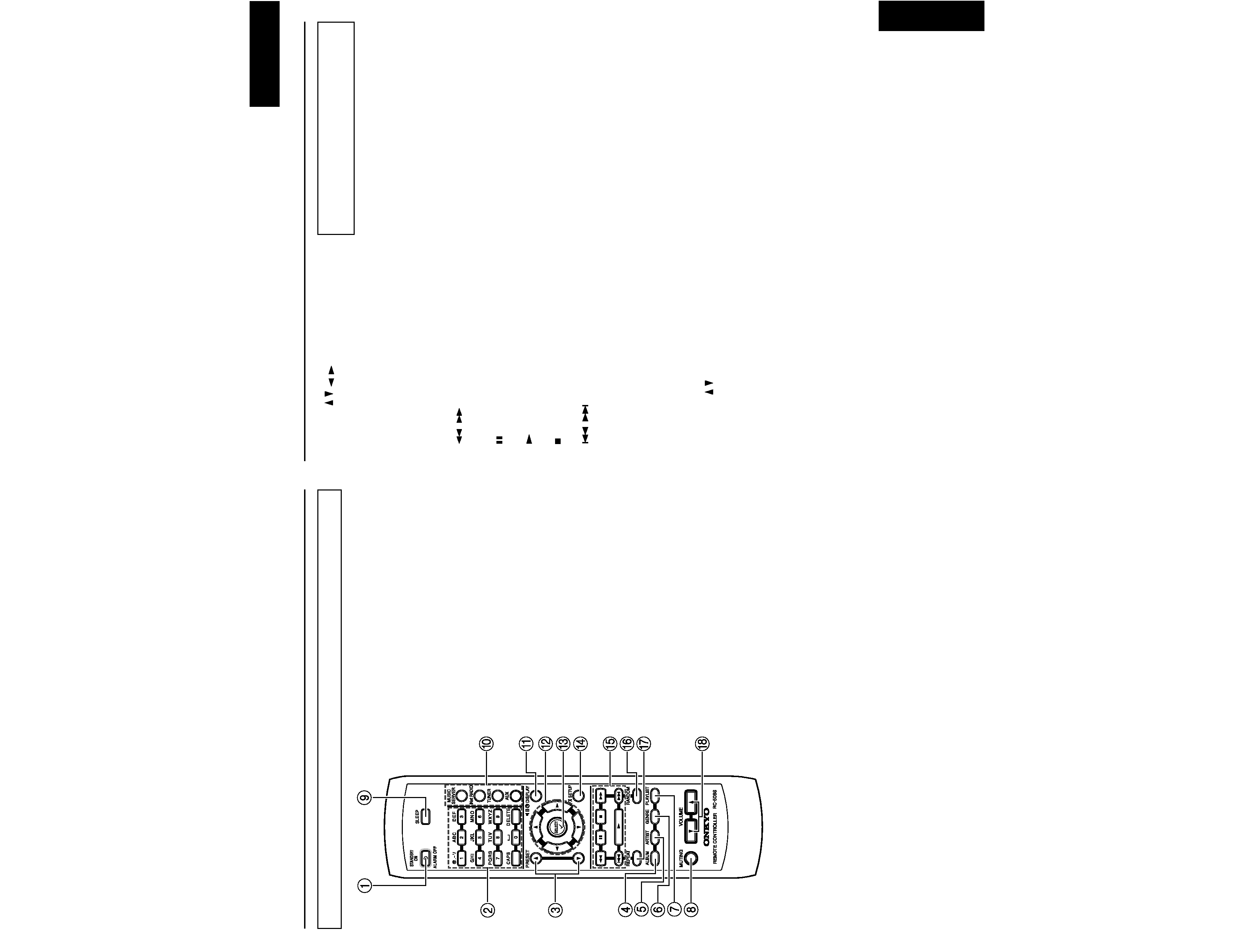
Index parts and facilities
1 STANDBY/ON button
Turns on the NC-500 or place it in standby
mode. When the NC-500 is in standby mode,
you can use this button to turn off the alarm.
2 Numeric keys
Press to select one of the preset stations or the
track you want to play. When entering text,
you use these buttons to type in letters and
special characters.
3 PRESET Up/Down buttons
Press to navigate through preset stations for
Internet radio or FM/AM radio.
4 ALBUM button
Press to invoke the Album selection menu
when working with the Net-Tune Central.
5 ARTIST button
Press to invoke the Artist selection menu
when working with the Net-Tune Central.
6 GENRE button
Press to invoke the Genre selection menu
when working with the Net-Tune Central.
7 PLAYLIST button
Press to invoke the Playlist selection menu
when working with the Net-Tune Central.
8 MUTING button
Press to activate the mute function. Press the
button again to disable the mute function.
9 SLEEP button
Press to set the sleep function.
0 MUSIC SERVER/iNetRADIO/TUNER/
AUX buttons
Press to select an input source. The TUNER
button toggles between FM and AM.
A DISPLAY button
Press to change the display mode.
Index parts and facilities
B Cursor / / /
buttons
Press to locate your selection.
C SELECT button
Press to save a new setting.
D SETUP button
Press to set up the NC-500.
E Operation buttons
,
(FR/FF) buttons
Press to fast-rewind or fast-forward the
current track.
(Pause) button
Press to pause the playback.
(Play) button
Press to start playback.
(Stop) button
Press to stop the playback.
,
B/F-Skip buttons
Press to move to the previous or next track.
F RANDOM button
Press to play the selected track list at random.
G REPEAT button
Press to repeat the selected single track or
track list.
H VOLUME / buttons
Press to adjust the volume.
Changing the remote controller
mode
When you use any Onkyo products other than the
NC-500 in the same room, the operations made
with the NC-500's remote controller may also
cause the other Onkyo products to operate. To
avoid this, you can change the remote controller
mode both for the NC-500 and its remote
controller choosing from three modes (1, 2 or 3).
To change the remote controller mode for the
remote controller, hold the STANDBY button on
the remote controller and press the SELECT
button, then release these buttons simultaneously.
Within 5 seconds after releasing the buttons, enter
the appropriate mode (1, 2 or 3) using the numeric
keys. The default mode is 1 for both the remote
controller and NC-500.
After changing the remote controller mode, make
sure that the remote control code on the NC-500 is
set to the same mode as the remote controller. (see
Page 63)
NC-500
NC-500
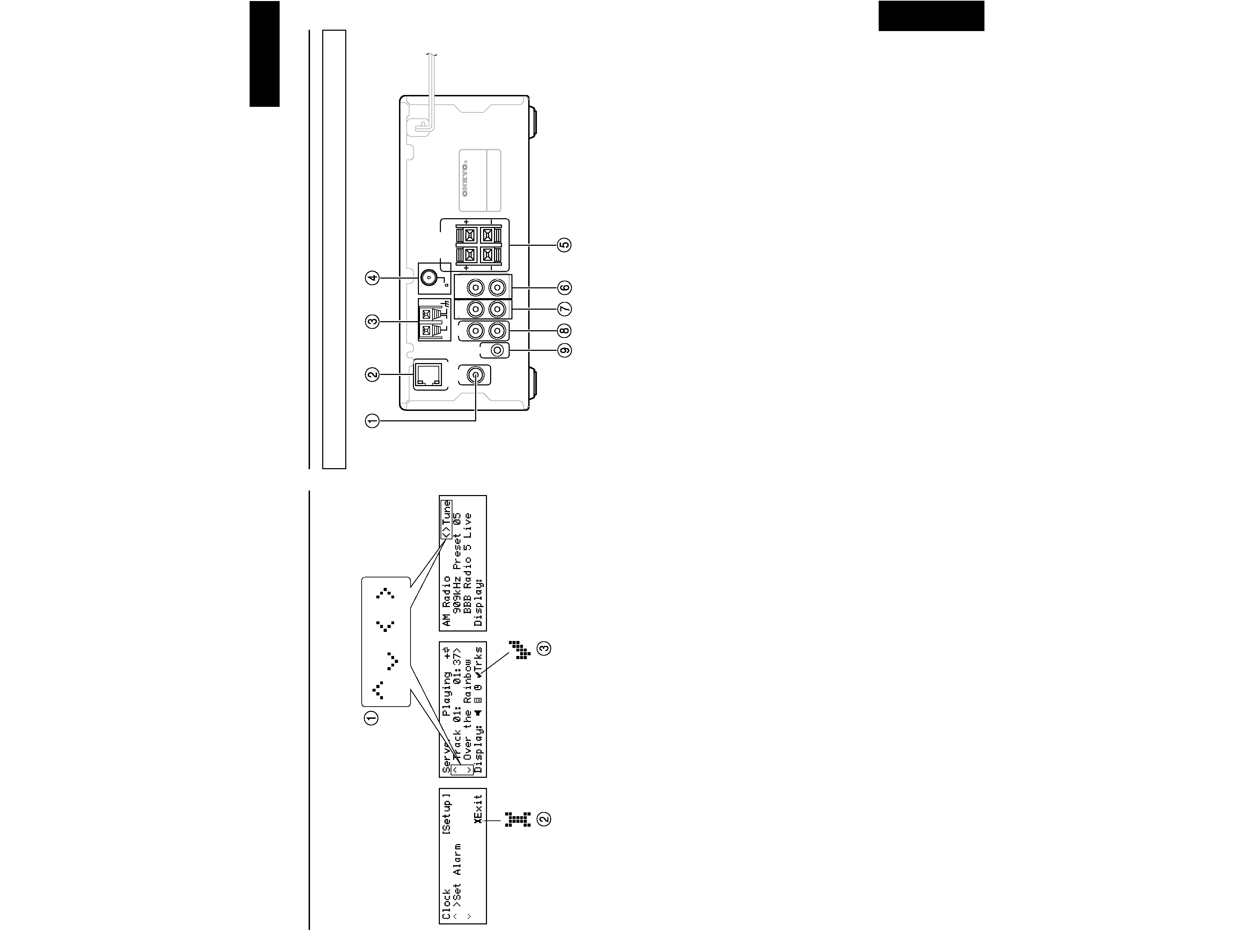
Index parts and facilities
(2) Operation guide icons
1 Up Arrow/ /Down Arrow/Left Arrow/Right Arrow
These icons are displayed to indicate that the corresponding cursor buttons are enabled to perform
specific actions.
Example: "< > Tune" indicates that you can use the Cursor Left and Right buttons to perform tuning
when the FM/AM radio feature is selected.
2 Setup
This icon is immediately followed by the command you can execute by pressing the SETUP button.
Example: When the Setup icon is immediately followed by "EXIT", you can press the SETUP
button to exit from the current menu.
3 Select
This icon is immediately followed by the command you can execute by pressing the SELECT
button.
Index parts and facilities
Rear Panel
1 OSD OUT
This port can be used to redirect screen output
from the front panel display to a television
screen for quick and easy large-screen
viewing.
2 ETHERNET
This port connects to a broadband mode,
router, hub, etc.
3 AM
This port connects to the AM radio antenna.
4 FM
This port connects to the FM radio antenna.
5 SPEAKERS
The terminals connect to the speakers.
6 VARIABLE OUTPUT
This port connects to an amplifier without
volume control.
7 FIXED OUT
This port connects to the input port of a
receiver with volume control.
ETHERNET
SPEAKERS
( 6 OHMS MIN. )
ANTENNA
AUX
IN
OUT
OUT
OUT
FIXED VARIABLE
OSD
AM
FM
75
R
L
27123044
UDD
R
L
R
L
AUDIO NETWORK RECEIVER
MODEL NO.
NC-
500
IN
IR
8 AUX
This port connects to an auxiliary device.
9 IR IN
If the NC-500 is located inside a rack or a
cabinet that will not allow infrared beams to
reach its IR sensor, you will need to relay
beams with an external sensor.
Connect the external sensor to IR IN input.
Then, place the sensor in an unblocked
location at which you can easily point with
the remote controller.