
Multizone Amplifier
MZA-4.7
Instruction Manual
2
Important Safety Instructions
1. Read these instructions.
2. Keep these instructions.
3. Heed all warnings.
4. Follow all instructions.
5. Do not use this apparatus near water.
6. Clean only with dry cloth.
7. Do not block any ventilation openings. Install in
accordance with the manufacturer's instructions.
8. Do not install near any heat sources such as radia-
tors, heat registers, stoves, or other apparatus
(including amplifiers) that produce heat.
9. Do not defeat the safety purpose of the polarized or
grounding-type plug. A polarized plug has two
blades with one wider than the other. A grounding
type plug has two blades and a third grounding
prong. The wide blade or the third prong are pro-
vided for your safety. If the provided plug does not
fit into your outlet, consult an electrician for
replacement of the obsolete outlet.
10. Protect the power cord from being walked on or
pinched particularly at plugs, convenience recepta-
cles, and the point where they exit from the appara-
tus.
11. Only use attachments/accessories specified by the
manufacturer.
12. Use only with the cart,
stand, tripod, bracket, or
table
specified
by
the
manufacturer, or sold with
the apparatus. When a cart
is used, use caution when
moving the cart/apparatus
combination
to
avoid
injury from tip-over.
13. Unplug this apparatus during lightning storms or
when unused for long periods of time.
14. Refer all servicing to qualified service personnel.
Servicing is required when the apparatus has been
damaged in any way, such as power-supply cord or
plug is damaged, liquid has been spilled or objects
have fallen into the apparatus, the apparatus has
been exposed to rain or moisture, does not operate
normally, or has been dropped.
15. Damage Requiring Service
Unplug the apparatus from the wall outlet and refer
servicing to qualified service personnel under the
following conditions:
A. When the power-supply cord or plug is dam-
aged,
B. If liquid has been spilled, or objects have fallen
into the apparatus,
C. If the apparatus has been exposed to rain or
water,
D. If the apparatus does not operate normally by
following the operating instructions. Adjust only
those controls that are covered by the operating
instructions as an improper adjustment of other
controls may result in damage and will often
require extensive work by a qualified technician
to restore the apparatus to its normal operation,
E. If the apparatus has been dropped or damaged in
any way, and
F. When the apparatus exhibits a distinct change in
performance this indicates a need for service.
16. Object and Liquid Entry
Never push objects of any kind into the apparatus
through openings as they may touch dangerous volt-
age points or short-out parts that could result in a
fire or electric shock.
The apparatus shall not be exposed to dripping or
splashing and no objects filled with liquids, such as
vases shall be placed on the apparatus.
Don't put candles or other burning objects on top of
this unit.
17. Batteries
Always consider the environmental issues and fol-
low local regulations when disposing of batteries.
18. If you install the apparatus in a built-in installation,
such as a bookcase or rack, ensure that there is ade-
quate ventilation.
Leave 20 cm (8") of free space at the top and sides
and 10 cm (4") at the rear. The rear edge of the shelf
or board above the apparatus shall be set 10 cm (4")
away from the rear panel or wall, creating a flue-like
gap for warm air to escape.
WARNING:
TO REDUCE THE RISK OF FIRE OR ELECTRIC
SHOCK, DO NOT EXPOSE THIS APPARATUS
TO RAIN OR MOISTURE.
CAUTION:
TO REDUCE THE RISK OF ELECTRIC SHOCK,
DO NOT REMOVE COVER (OR BACK). NO
USER-SERVICEABLE PARTS INSIDE. REFER
SERVICING
TO
QUALIFIED
SERVICE
PERSONNEL.
The lightning flash with arrowhead symbol, within an
equilateral triangle, is intended to alert the user to the
presence of uninsulated "dangerous voltage" within
the product's enclosure that may be of sufficient
magnitude to constitute a risk of electric shock to
persons.
The exclamation point within an equilateral triangle is
intended to alert the user to the presence of important
operating and maintenance (servicing) instructions in
the literature accompanying the appliance.
WARNING
RISK OF ELECTRIC SHOCK
DO NOT OPEN
RISQUE DE CHOC ELECTRIQUE
NE PAS
OUVRIR
AVIS
PORTABLE CART WARNING
S3125A
3
Quick Install Guide
Unpacking
Immediately upon receiving your MZA-4.7 inspect the
carton for evidence of mishandling during shipment.
Then carefully unpack the unit and inspect for damage.
Please save the shipping carton and all inner packing
materials in the event that the MZA-4.7 needs to be
shipped for service or moved to a new location.
Should you discover that the MZA-4.7 has been damaged
during shipping please contact your dealer immediately.
1. Check website for latest firmware, and upload if not
current.
2. If adding an amplifier to an exiting stack or combin-
ing amplifiers all firmware must be the same on all
amplifiers
3. Zone setting. The units all ship with zones 1,2,3,4
already setup.
To add additional amplifiers to a stack the zones
must be changed on the additional amplifiers. If
there are zone duplications in a stack of amplifiers
the zones with the same number will exactly mirror
each other's operation.
To change an amplifier zone follow the following
steps.
·
Do not connect the expansion bus cable.
·
From the front facia rotate the Knob to select the
appropriate amplifier turn it on, and then select the
"More" menu (right arrow). Scroll through the menu
and select "Set Zone" and change to the required
assignment pushing the Knob to set.
4. Wire the keypads to the rear of the amplifier.
5. To setup the keypad follow the Controllers instruc-
tion manual, Briefly:
·
with a zone, press the SET key (behind the cover plate)
followed by the S2 key.
·Turn the required amplifier zone ON and OFF twice.
The Keypad beeps signalling it has been successfully
zoned. The Keypad now controls that zone.
·
Learn codes into the Keypad by first selecting the
source button ie S3. Press the SET key followed by the
S1 key to enter keypad IR learning mode.
·
Press the button you want to learn an IR code into.
·
Align the remote with the front lower window and
press the button on the remote to donate the IR code to
that button. Continue learning codes for that source.
·
Press the SET key to exit learn mode.
·
Select the next source, ie S2. Then press SET followed
by S1 and repeat the learning process.
6. To prevent a user from changing the MZA-4.7's
critical installation settings, "Setup Lockout" can be
selected in the Setup Menu. To enter the setup menu
press and hold the multi jog for > 10 second, scroll
through to "Setup Lockout" enter and select "Yes."
The "Setup" and "More" menus on the amplifier are
no longer accessible to the user.
7. To unlock the MZA-4.7, return to the setup menu as
above. And enter the password: 1396
Table of Contents
Important Safety Instructions...............................2
Quick Install Guide ..............................................3
Supplied Accessories ..........................................3
Precautions .........................................................4
Features ..............................................................5
Part Names and Functions..................................7
Typical System Configuration..............................9
Controller Termination.......................................11
Advanced IR Control .........................................12
Multiple MZA-4.7 Stacks ...................................13
Zone Linking......................................................14
Automation ........................................................15
RS232 Protocol .................................................16
Menu Navigation ...............................................20
Programming Using IMC (Integra Music Center)......22
Specifications ....................................................28
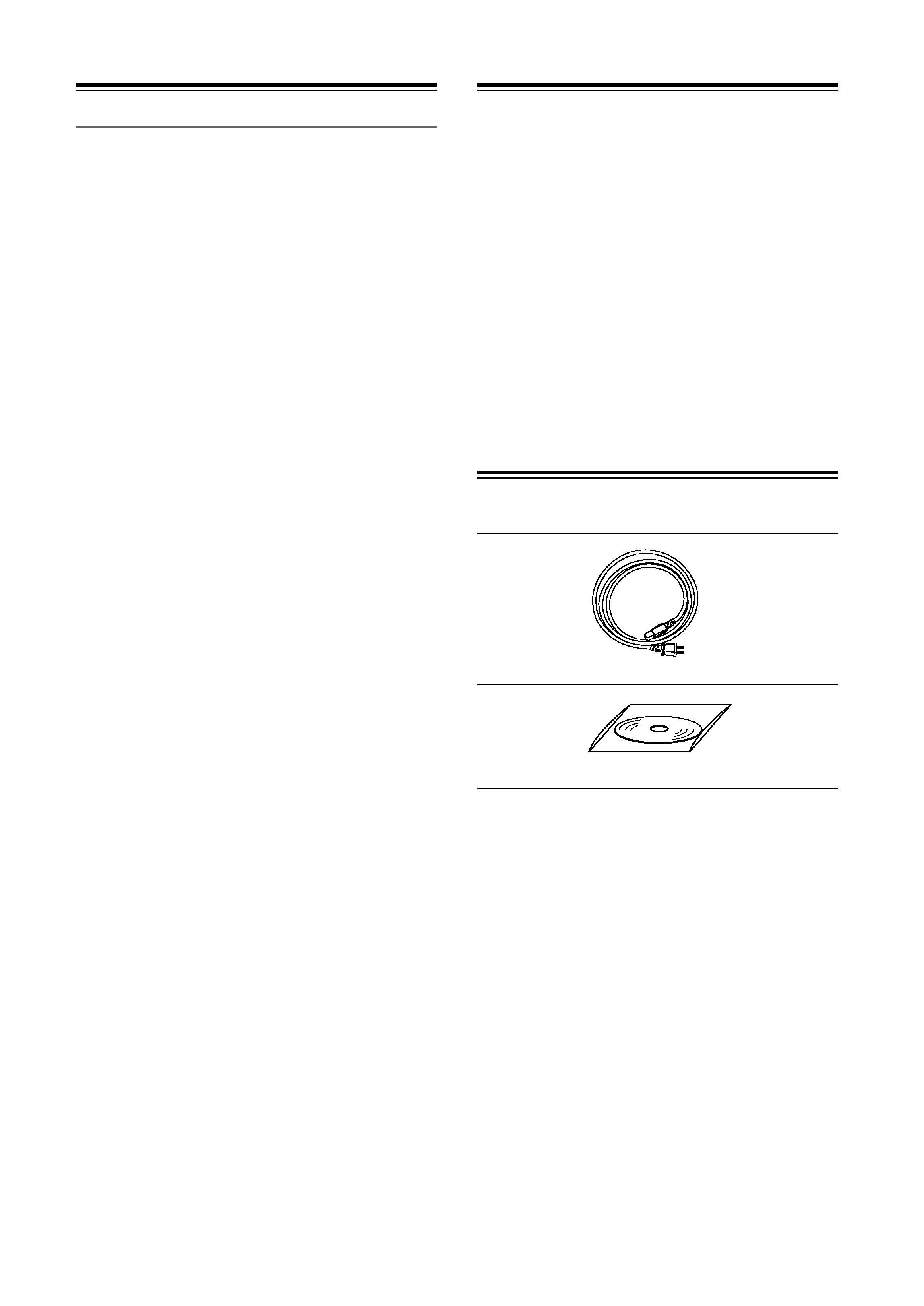
Supplied Accessories
Make sure you have the following accessories:
*In catalogs and on packaging, the letter at the end of the product
name indicates the color. Specifications and operations are the
same regardless of color.
AC Power Cable
CD-ROM

4
Precautions
1. Recording Copyright--Unless it's for personal use
only, recording copyrighted material is illegal with-
out the permission of the copyright holder.
2. AC Fuse
CAUTION:
FOR CONTINUED PROTECTION AGAINST
RISK OF FIRE REPLACE ONLY WITH SAME
TYPE T6.3A 250V FUSE.
REFER REPLACEMENT TO QUALIFIED SER-
VICE PERSONNEL.
3. Care--Occasionally you should dust the unit all
over with a soft cloth. For stubborn stains, use a soft
cloth dampened with a weak solution of mild deter-
gent and water. Dry the unit immediately afterwards
with a clean cloth. Don't use abrasive cloths, thin-
ners, alcohol, or other chemical solvents, because
they may damage the finish or remove the panel let-
tering.
4. Power
WARNING
BEFORE PLUGGING IN THE UNIT FOR THE
FIRST TIME, READ THE FOLLOWING SEC-
TION CAREFULLY.
AC outlet voltages vary from country to country.
Make sure that the voltage in your area meets the
voltage requirements printed on the unit's rear panel
(e.g., AC 230 V, 50 Hz or AC 120 V, 60 Hz).
The power cord plug is used to disconnect this unit
from the AC power source. Make sure that the plug
is readily operable (easily accessible) at all times.
5. Never Touch this Unit with Wet Hands--Never
handle this unit or its power cord while your hands
are wet or damp. If water or any other liquid gets
inside this unit, have it checked by your Onkyo
dealer.
6. Handling Notes
· If you need to transport this unit, use the original
packaging to pack it how it was when you origi-
nally bought it.
· Do not leave rubber or plastic items on this unit
for a long time, because they may leave marks on
the case.
· This unit's top and rear panels may get warm
after prolonged use. This is normal.
· If you do not use this unit for a long time, it may
not work properly the next time you turn it on, so
be sure to use it occasionally.
7. Speaker Shorts--Under no circumstances should
the speaker output terminals of the unit be short cir-
cuited, or connected to another output.
8. RS232 Connection--Avoid plugging the RS232
cable into the unit while power is connected.
9. Direct Sun light--Avoid installing the amplifier in
positions where the front panel is exposed to direct
sunlight may cause control to become sluggish.
10. Controller Connection--Never connect more than
four controllers to the 12VDC power supply termi-
nals. The supply is internally fused and will open
circuit (self-resetting) Never connect the amplifier's
12VDC terminals to an external power supply.
For U.S. models
FCC Information for User
CAUTION:
The user changes or modifications not expressly
approved by the party responsible for compliance could
void the user's authority to operate the equipment.
NOTE:
This equipment has been tested and found to comply
with the limits for a Class B digital device, pursuant to
Part 15 of the FCC Rules. These limits are designed to
provide reasonable protection against harmful interfer-
ence in a residential installation.
This equipment generates, uses and can radiate radio
frequency energy and, if not installed and used in accor-
dance with the instructions, may cause harmful interfer-
ence to radio communications. However, there is no
guarantee that interference will not occur in a particular
installation. If this equipment does cause harmful inter-
ference to radio or television reception, which can be
determined by turning the equipment off and on, the
user is encouraged to try to correct the interference by
one or more of the following measures:
· Reorient or relocate the receiving antenna.
· Increase the separation between the equipment and
receiver.
· Connect the equipment into an outlet on a circuit dif-
ferent from that to which the receiver is connected.
· Consult the dealer or an experienced radio/TV tech-
nician for help.
For Canadian Models
NOTE: THIS CLASS B DIGITAL APPARATUS
COMPLIES WITH CANADIAN ICES-003.
For models having a power cord with a polarized plug:
CAUTION: TO PREVENT ELECTRIC SHOCK,
MATCH WIDE BLADE OF PLUG TO WIDE SLOT,
FULLY INSERT.
Modèle pour les Canadien
REMARQUE: CET APPAREIL NUMÉRIQUE DE
LA CLASSE B EST CONFORME À LA NORME
NMB-003 DU CANADA.
Sur les modèles dont la fiche est polarisée:
ATTENTION: POUR ÉVITER LES CHOCS ÉLEC-
TRIQUES, INTRODUIRE LA LAME LA PLUS
LARGE DE LA FICHE DANS LA BORNE CORRE-
SPONDANTE DE LA PRISE ET POUSSER
JUSQU'AU FOND.

5
Features
Thank you for purchasing an Integra MZA-4.7 Multi-Zone Amplifier.
Please read this manual thoroughly before making connections and plugging in the unit.
Following the instructions in this manual will enable you to obtain optimum performance and listening
enjoyment from your new Multi-Zone Amplifier.
Please retain this manual for future reference.
Multi-Zone, Multi-Source, Video Switching
The MZA-4.7 has four separate preamplifiers and ampli-
fiers, providing 4 zones of independent yet integrated
control.
There are seven stereo sources (S1 - S7) and an eighth
mono source (S8) typically used for paging applications.
Each zone has an eight-source composite video switcher,
so monitor screen's in four different rooms may display
any of the eight sources (S1 - S8).
Preamplifiers and Outputs
Each zone has bass, treble, balance and loudness control.
These are accessed either from the front panel or IMC
(Integra Music Center) program.
The preamplifier output volume may be independent of
the amplifier volume, or made to track the amplifier with
an adjustable offset (± 20dB). The tracking feature is
ideal for passive subwoofer control, while the indepen-
dent volume feature is useful for limited control in
closecoupled rooms.
A useful protection feature is "Maximum Volume limit-
ing." This limits the maximum volume of either the
amplifier or preamplifier.
Amplifier Power, Protection, and Clipping
Indicators
50 Watts RMS per channel into 8 ohms, capable of driv-
ing into 6 ohms.
The amplifiers are protected against short-term output
shorts.
The front panel zone indicators will flash red when the
zone amplifiers are overdriven into clipping.
Thermal Control
There are three progressive levels of thermal control:
· An internal fan is turned on to aid cooling.
· The amplifier volume is reduced 20dB.
· The amplifiers are shutdown until the temperature
reduces below the first level.
Care should be taken to ensure adequate ventilation see
"Important Safety Instructions" on page 2.
USB, RS232 and IR Control
The MZA-4.7 may be controlled and monitored via
either the front Panel USB or rear panel RS232 serial
interface.
In multi amplifier installations where the amplifiers are
interconnected using an expansion bus cable, only one
USB or RS232 connection is required to control the
stack of amplifiers.
A MZA-4.7 may receive IR directly from the front panel
receiver or via the two "Controller Interface" connec-
tions.
There are zone specific IR commands and also a set of
global IR commands.
The commands are: ON, OFF, Standby (toggling), Mute,
Amp Volume Up, Amp Volume Down, Pre Volume Up,
Pre Volume Down, Source Selects, On with Source Spe-
cific commands.
The Global commands also include PRESET1 - PRE-
SET 6, Alarm Enable, Alarm OFF, and 5 minute Sleep.
Real Time Clock
The MZA-4.7 is equipped with a real time clock.
The amplifier may be set up to function as an alarm
clock, so that at 6.30am in the morning 5 days a week,
the master bedroom zone could be made to turn on,
select tuner, and go to a specific volume. Multiple
Alarms are feasible (max of 6) However the Alarm
Enable & OFF commands act upon all programmed
Alarms.
The clock continues to operate typically > 48 hours with-
out power more than enough to keep the time current
during lengthy power outages.
IR Emitter Ports
There are 4 Buffered IR emitter Ports.
Two IR ports have routing, and are linked to their respec-
tive "Controller Interface" ports. These ports control
zone specific source components. Two IR ports are the
sum of both IR sources; these control the All zone source
components.
Presets and Paging
There are six amplifier presets and a page preset.
Presets 1 - 6 are momentary and cause the amplifier to go
to a predetermined setup, i.e. standby, volume & source
selection.
The presets may also be programmed with event sched-
uling, and are used by the alarm clock.
The "Page Preset" mode is for paging applications and is
invoked by a contact closure between the "0V" and the
"PG" terminals. When the contact closure is released the
amplifier zones return to their previous states.
Zone Linking
A zone may be programmed to link one other zone. Zone
linking ties the source selection together. It may also tie
the volume, and standby.
This is useful for closely coupled audio areas where it is