DV-SP301
SERVICE MANUAL
SERVICE MANUAL
DVD PLAYER
Black, Silver and Golden models
MODEL
DV-SP301
Ref. No. 3761
052003
B UDD, S UDD
120V AC, 60Hz
B UUS, S UUS
230-240V AC, 50Hz
G UUK, G UUT
220-230V AC, 50/60Hz
RC-458DV
SAFETY-RELATED COMPONENT
WARNING!!
THE MARK
FOUND ON SOME COMPONENT
PARTS INDICATES THE CRITICAL FOR RISK OF
FIRE AND ELECTRIC SHOCK.
WHEN REPLACING, BE SURE TO USE PARTS OF
IDENTICAL DESIGNATION.
MAKE LEAKAGE-CURRENT OR RESISTANCE
MEASUREMENTS TO DETERMINE THAT EXPOSED
PARTS ARE ACCEPTABLY INSULATED FROM THE
SUPPLY CIRCUIT BEFORE RETURNING THE
APPLIANCE TO THE CUSTOMER.

DV-SP301
SPECIFICATIONS
DVD Player
Power supply
AC120 V, 60 Hz (North America models)
Power consumption
16 W
Weight
External dimensions
Signal system
Regional restriction code
Region 1 (North America)
(region number)
Region 4 (Central and South America and Australia)
Frequency range (digital audio)
48 kHz sampling 4 Hz to 22 kHz
(DVD linear sound)
96 kHz sampling 4 Hz to 44 kHz
Signal-to-noise ratio (digital audio)
More than 90 dB
Audio dynamic range (digital audio)
More than 95 dB
Harmonic distortion (digital audio)
Less than 0.005 %
Wow and flutter
Below measurable level
Operating conditions
Temperature: 5°C to 35°C (41°F to 95°F)
Operation status: Horizontal
Outputs
Video output
1.0 V (p-p), 75 W, negative sync., pin jack
1
S-video output
(Y) 1.0 V (p-p), 75 W, negative sync., Mini DIN 4-pin
1
(C) 0.286 V (p-p), 75 W
Component video output
(Y) 1.0 V (p-p), 75 W, negative sync., pin jack
1
(PB)/(PR) 0.7 V (p-p), 75 W, pin jack
2
Audio output (digital output Optical)
Optical connector
1
Audio output (digital output Coaxial)
0.5 V (p-p), 75 W, pin jack
1
Audio output (2-Channel Audio)
2.0 V (rms), 320 W, pin jack (L, R)
1
Specifications and features are subject to change without notice.
AC 110-240V, 50/60Hz (Other models)
8.2 lbs
17-1/8" x 3-7/8" x 12-11/16" (W/H/D)
NTSC (North America models)
PAL/NTSC (Other models)
x
x
x
x
x
x
x
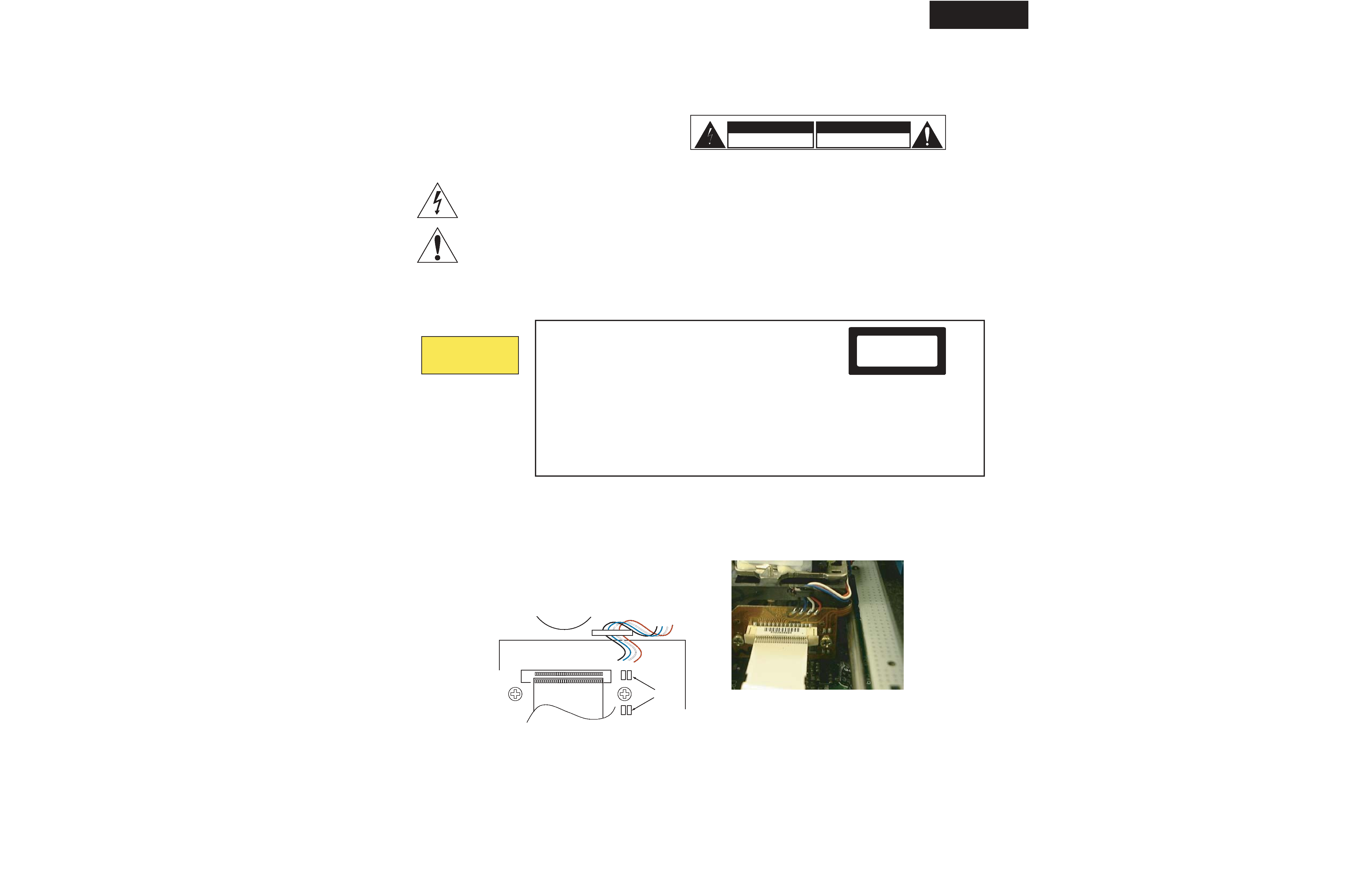
FFC
Short land
DV-SP301
SERVICE PROCEDURE
REPLACING THE FUSES
SAFETY CHECK
(Only U.S.A. model)
After correcting the original service problem perform the
following safety check before releasing the set to the customer
Connect the insulating-resistance tester between the plug of
power supply cord and terminal GND on the back panel.
Specifications: More than 10M ohm at 500V
The lightning flash with arrowhead symbol, within an equilateral triangle, is
intended to alert the user to the presence of uninsulated "dangerous voltage"
within the product's enclosure that may be of sufficient magnitude to constitute
a risk of electric shock to persons.
The exclamation point within an equilateral triangle is intended to alert the user
to the presence of important operating and maintenance (servicing) instruction
in the literature accompanying the appliance.
RISK OF ELECTRIC SHOCK
DO NOT OPEN
WARNING
AVIS
RISOUE DE CHOC ELECTRIQUE
NE PAS OUVRIR
This unit contains a semiconductor laser system and is classified as a
"CLASS 1 LASER PRODUCT". So, to use this model properly, read
this Instruction Manual carefully . In case of any trouble, please contact
the store where you purchased the unit. To prevent being exposed to the
laser beam, do not try to open the enclosure.
CAUTION:
VISIBLE LASER RADIATION WHEN OPEN AND INTERLOCK
FAILED OR DEFEATED. DO NOT STARE INTO BEAM.
CAUTION:
THIS PRODUCT UTILIZES A LASER. USE OF CONTROLS OR
ADJUSTMENTS OR PERFORMANCE OF PROCEDURES OTHER
THAN THOSE SPECIFIED HEREIN MAY RESULT IN
HAZARDOUS RADIATION EXPOSURE.
The label on the right is
applied on the rear
panel except for USA
and Canadian models.
1. This unit is a CLASS 1 LASER PRODUCT and employs a laser
inside the cabinet.
2. To prevent the laser from being exposed, do not remove the
cover. Refer servicing to qualified personnel.
"CLASS 1 LASER
PRODUCT "
LASER CAUTION
CAUTION
VISIBLE AND INVISIVLE LASER RADIATION
WHEN OPEN DO NOT STARE INTO THE BEEM OR
VIEW DIRECTLY WITH OPTICAL INSTRUMENTS.
DO NOT PRESS ON THIS SURFACE
1.Remove the solder of Laser Diode shorting
1-1
Remove the bracket magnet.
1-2
Shorting the short land with solder.
1-3
Remove the FFC (CC21) and other connectors.
2. Factory setting (Initial setting)
2-1 Push the power switch "ON" (Mechanical switch)
2-2 Press the [STOP] and [STANDBY ON] keys at same time, and
it waits until the display of FL tube will be the display of "No Disc" from "Loading".
F1
0215002_M
Fuse, 250V 2A
CIRCUIT NO. PART NO.
DESCRIPTION
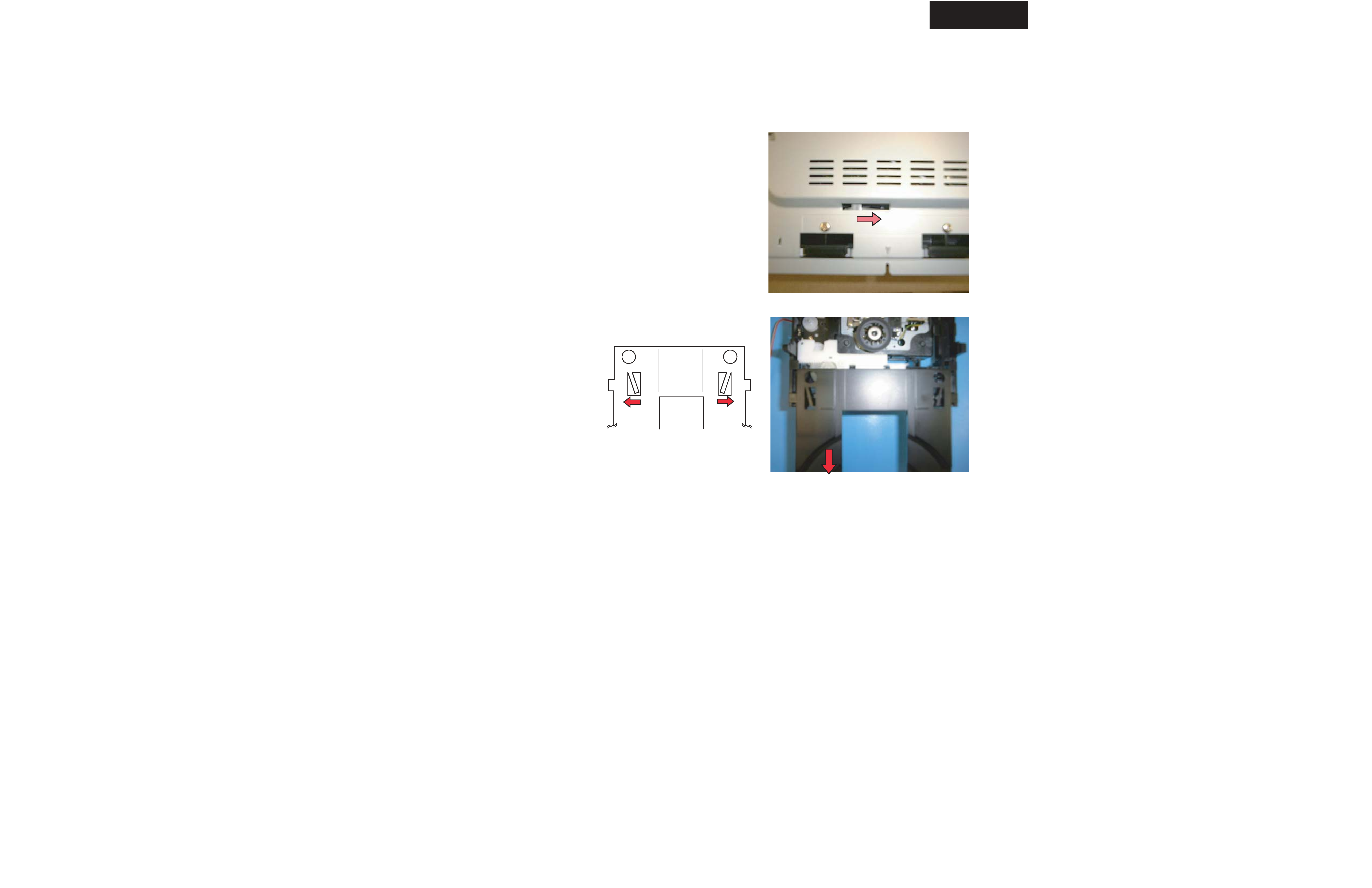
Bottom side
Fig-1
DV-SP301
SERVICE PROCEDURE-2
Replace the DVD mechanism
1. Remove the top cover (six screws)
2. Remove two screws of both side of front panel.
3. Remove the bracket mecha. (two screws).
4. Shift the cam slider on bottom side. (See Fig-1)
5. Remove the tray.
6. Remove FFC, connector and one screw (Mecha. GND wire).
7. A tray is drawn out extending a nail. (See Fig-2)
8. Remove two screws (3 x 6 upper side) and
two screws (3 x 8 bottom side).
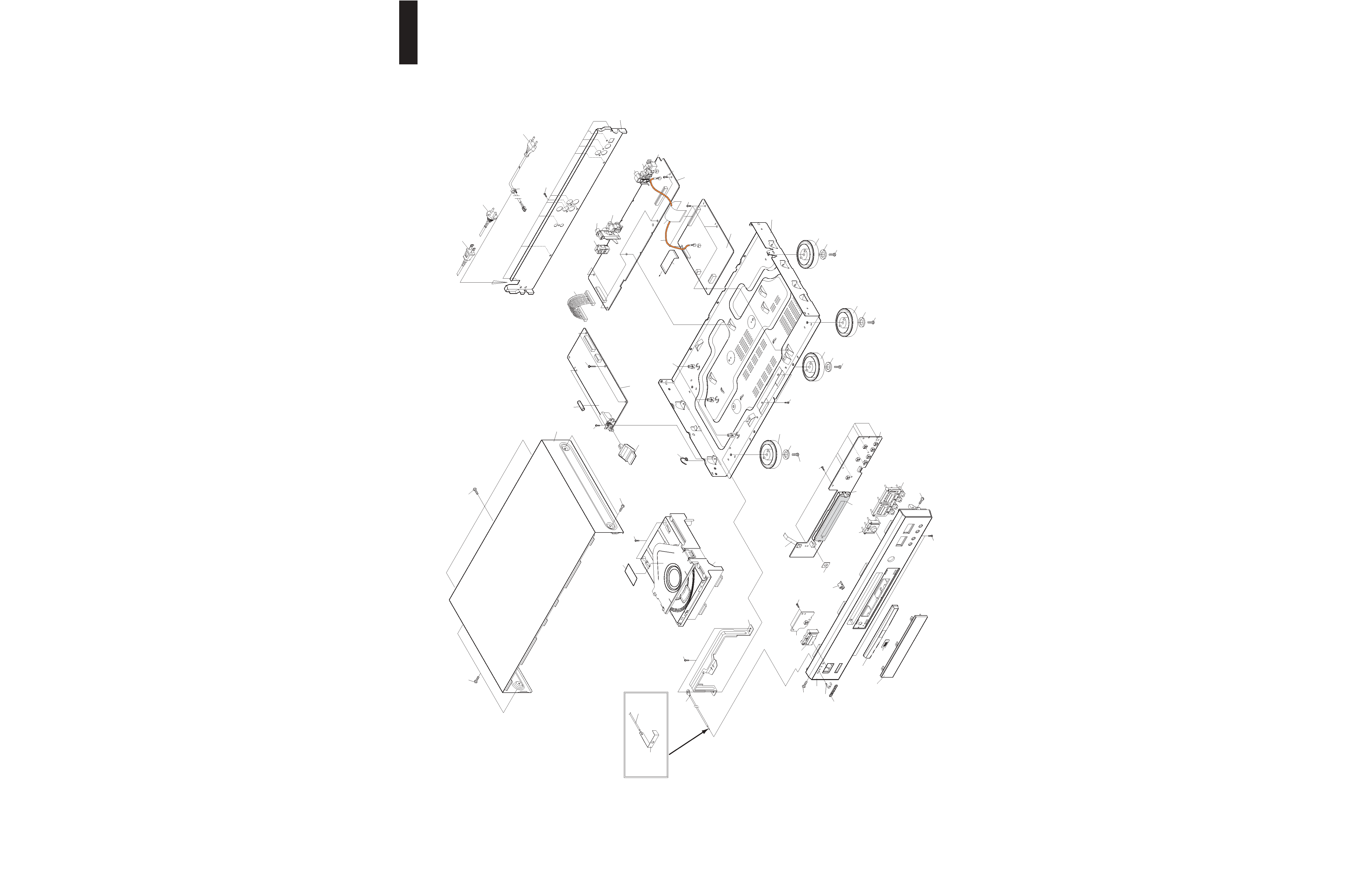
DV-SP301
EXPLODED VIEW
CHASSIS
36
36
7
11
10
9
8
7
6
5
4
3
2
1
16
15
S7 x 8
S8
17
18
S8
17
18
S8
17
18
S8 x 2
S8
17
18
19
20
S2 x 4
19
S2 x 5
22
23
24
25
26
27
28
S4 x 11
29
30
UUS4P & UUT3P
30
UUK3P
30
UUD1N
S5 x 3
S2 x 2
31
32
S3 x 2
33
S1 x 2
34
S2 x 2
35
S7 x 3
S6
S9
12
13
S9
37 x 3
S3 x 2
S3 x 2
S1
S2
S3
S4
S5
S6
S7
S8
S9
3 x 6Y BK/BH
3 x 8 ZNY/BH
3 x 10 BK/BH <B>
3 x 8 Silver/BH <S> <G>
3 x 10 BK/BH DOT
3 x 18 W/Washer
3 x 10 BK/BH <B>
3 x 8 W/Washer <S> <G>
2.6 x 8 ZNY/PH
3 x 10 BK/BH
3 x 8 BK/FH
SCREW
14
CC24
CN25
CN81
CC21
To Mecha.
CA
TI
O
N
41
40 x 3
NOTE: <B>: Black color
<S>: Silver color
<G>: Golden color
F1