DV-CP701
SERVICE MANUAL
SERVICE MANUAL
DVD CHANGER
Black and Silver models
MODEL
DV-CP701
120V AC, 60Hz
220-230V AC, 50/60Hz
B MDD, S MDD
B MPA
Ref. No. 3760
052003
ON
STANDBY
SEARCH LAST M MEMORY CHAIN MODE
REPEAT
A-B
RANDOM
DISPLAY
MENU
SETUP
TOP MENU
RETURN
AUDIO
ANGLE SUBTITLE ZOOM
DISC
1
DISC
2
DISC
3
DISC
4
DISC
5
DISC
6
DISC SKIP
DIMMER
RC-542DV
STEP/SLOW
CLEAR
OPEN/
CLOSE
PROGRESSIVE
ENTER
+10
0
123
456
789
RC-542DV
SAFETY-RELATED COMPONENT
WARNING!!
COMPONENTS IDENTIFIED BY MARK
ON THE
SCHEMATIC DIAGRAM AND IN THE PARTS LIST ARE
CRITICAL FOR RISK OF FIRE AND ELECTRIC SHOCK.
REPLACE THESE COMPONENTS WITH ONKYO
PARTS WHOSE PART NUMBERS APPEAR AS SHOWN
IN THIS MANUAL.
MAKE LEAKAGE-CURRENT OR RESISTANCE
MEASUREMENTS TO DETERMINE THAT EXPOSED
PARTS ARE ACCEPTABLY INSULATED FROM THE
SUPPLY CIRCUIT BEFORE RETURNING THE
APPLIANCE TO THE CUSTOMER.
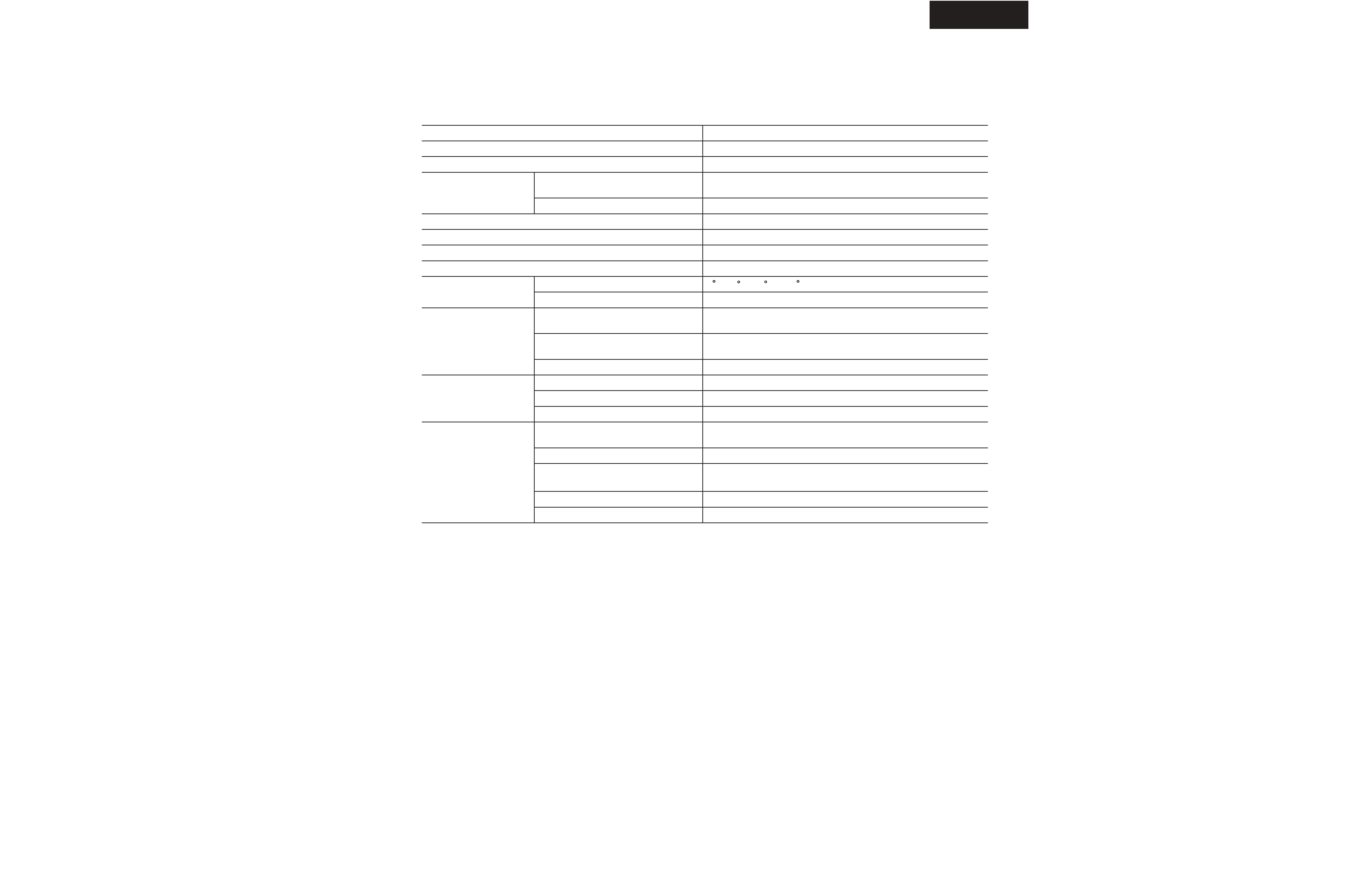
DV-CP701
SPECIFICATIONS
SpeciÞcations and features subject to change without notice.
Video system
Standard NTSC (U.S. model), PAL/AUTO (Australian model)
Region code
1 (U.S. model), 4 (Australian model)
Laser
Semiconductor laser, wavelength 650 nm (DVD), 780 nm (CD)
Frequency response
DVD linear audio
4 Hz-22 kHz @ 48 kHz sampling rate
4 Hz-44 kHz @ 96 kHz sampling rate
CD audio
4 Hz-20 kHz
Signal-to-noise ratio (digital audio)
100 dB
Audio dynamic range (digital audio)
96 dB
Harmonic distortion (digital audio)
0.001%
Wow and futter
Below measurable level (+/-0.001% (W. PEAK)) or less
Operating conditions
Temperature
5 to 35 C (41 F to 95 F)
Installation
Install horizontally
Video outputs
COMPONENT VIDEO
Y: 1.0 V (p-p), 75 ohm , negative sync, RCA/phono x 3
PB/PR: 0.7 V (p-p), 75 ohm
S VIDEO (S-Video)
Y: 1.0 V (p-p), 75 ohm , negative sync, 4-pin mini DIN x 1
C: 0.286 V (p-p), 75 ohm
VIDEO (composite video)
1.0 V (p-p), 75 ohm, negative sync, RCA/phono x 1
Audio outputs
OPTICAL
Optical connector x 1
COAXIAL
0.5 V (p-p), 75 ohm, RCA/phono x 1
ANALOG
2.0 V rms, 470 ohm, RCA/phono x 2
General
Power supply
120 V AC, 60 Hz (U.S. model)
220-230 V AC, 50/60 Hz (Australian model)
Power consumption
13 W
Power consumption in Standby
mode
1.6 W (U.S. model)
2.0 W (Australian model)
Weight
5.3 kg (11.7 lbs.)
Dimensions (W x H x D)
435 X 91 X 432 mm (17-1/8 X 3-9/16 X 17)
DV-CP701
SERVICE PROCEDURES-1
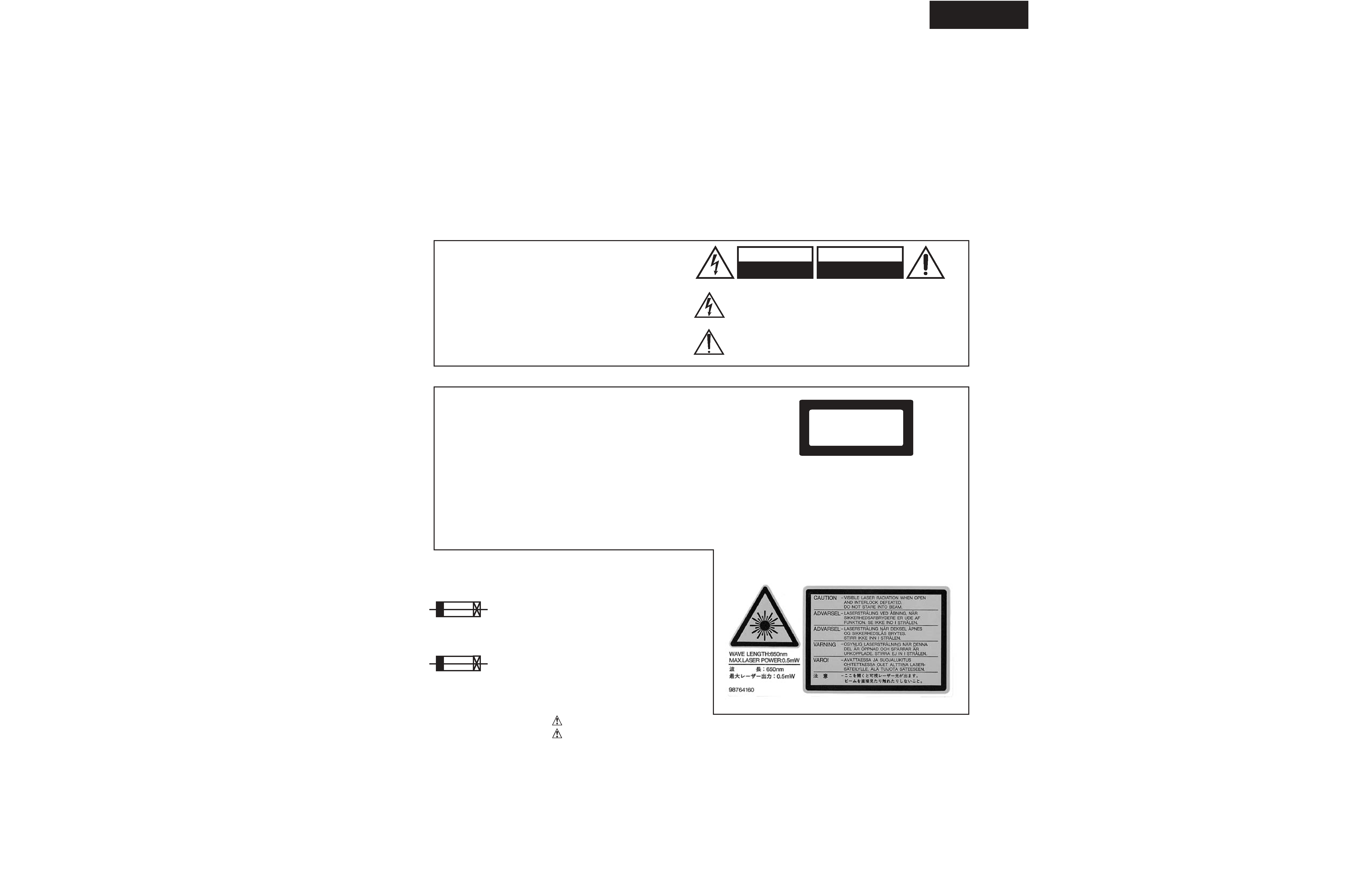
PROTECTION OF EYES FROM LASER BEAM DURING SERVICING
This set employs a laser. Therefore, be sure to follow
carefully the instructions below when servicing.
WARNING!!
SERVICE WARNING : DO NOT APPROACH THE
LASER EXIT WITH THE EYE TOO CLOSELY.
IN CASE IT IS NECESSARY TO CONFIRM LASER
BEAM EMISSION, BE SURE TO OBSERVE FROM
A DISTANCE OF MORE THAN 30cm FROM THE
SURFACE OF THE OBJECTIVE LENS ON THE
OPTICAL PICKUP BLOCK.
Laser Diode Properties
LASER WARNING
Wavelength: 650/780nm (DVD/CD)
WARNING:
TO REDUCE THE RISK OF FIRE OR ELECTRIC SHOCK,
DO NOT EXPOSE THIS APPLIANCE TO RAIN OR
MOISTURE.
CAUTION:
TO REDUCE THE RISK OF ELECTRIC SHOCK, DO NOT
REMOVE COVER (OR BACK). NO USER-SERVICEABLE
PARTS INSIDE. REFER SERVICING TO QUALIFIED
SERVICE PERSONNEL.
The lightning flash with arrowhead symbol, within an equilateral
triangle, is intended to alert the user to the presence of uninsulated
"dangerous voltage" within the product's enclosure that may be of
sufficient magnitude to constitute a risk of electric shock to persons.
The exclamation point within an equilateral triangle is intended to alert
the user to the presence of important operating and maintenance
(servicing) instructions in the literature accompanying the appliance.
WARNING
RISK OF ELECTRIC SHOCK
DO NOT OPEN
RISQUE DE CHOC ELECTRIQUE
NE PAS
OUVRIR
AVIS
WARNING
This unit contains a semiconductor laser system and is classified
as a "CLASS 1 LASER PRODUCT". So, to use this model
properly, read this Instruction Manual carefully. In case of any
trouble, please contact the store where you purchased the unit.
To prevent being exposed to the laser beam, do not try to open
the enclosure.
VISIBLE LASER RADIATION WHEN OPEN AND INTERLOCK
FAILED OR DEFEATED. DO NOT STARE INTO BEAM.
THIS PRODUCT UTILIZES A LASER. USE OF CONTROLS OR
ADJUSTMENTS OR PERFORMANCE OF PROCEDURES
OTHER THAN THOSE SPECIFIED HEREIN MAY RESULT IN
HAZARDOUS RADIATION EXPOSURE.
The label on the right
is applied on the rear
panel except for USA
and Canadian
models.
1. This unit is a CLASS 1 LASER PRODUCT and employs a
laser inside the cabinet.
2. To prevent the laser from being exposed, do not remove
the cover. Refer servicing to qualified personnel.
"CLASS 1 LASER
PRODUCT "
CAUTION:
CAUTION:
SERVICE PROCEDURE
1. Replacing the fuses
REF. NO.
PART NO.
DESCRIPTION
This symbol located near the fuse indicates that the
fuse used is show operating type, For continued protection against
fire hazard, replace with same type fuse , For fuse rating, refer to
the marking adjest to the symbol.
Ce symbole indique que le fusible utilise est e lent.
Pour une protection permanente, n'utiliser que des fusibles de meme
type. Ce demier est indique la qu le present symbol est apposre.
F001
252185 or
1.6A-UL/T-237
252252
1.6A-T/UL-ST2
LASER BEAM CAUTION LABEL
<MDD>
252075 or
252275
2.5A-SE-EAK
2.5A-SE-TL250V <MPA>
North American area
Australian area
F001

DV-CP701
SERVICE PROCEDURES-2
Factory-shipped condition
Push button "ON" (Mechanical SW)
Press the [STOP] and [STANDBY] same time with NO DISC condition.
Push button "STANDBY".
After display "COMPLETE".
INITIALIZING
2. Safety-check out
(Only U.S.A. model)
After correcting the original service problem perform the
following safety check before releasing the set to the customer
Connect the insulating-resistance tester between the plug of
power supply cord and terminal GND on the back panel.
Specifications: More than 10M ohm at 500V
REMOVE THE SOLDER OF LASER DIODE SHORT
When replace the mechanism or DVD main PC board.
Shotting the solder of Shot-circuit land. (2 positions)
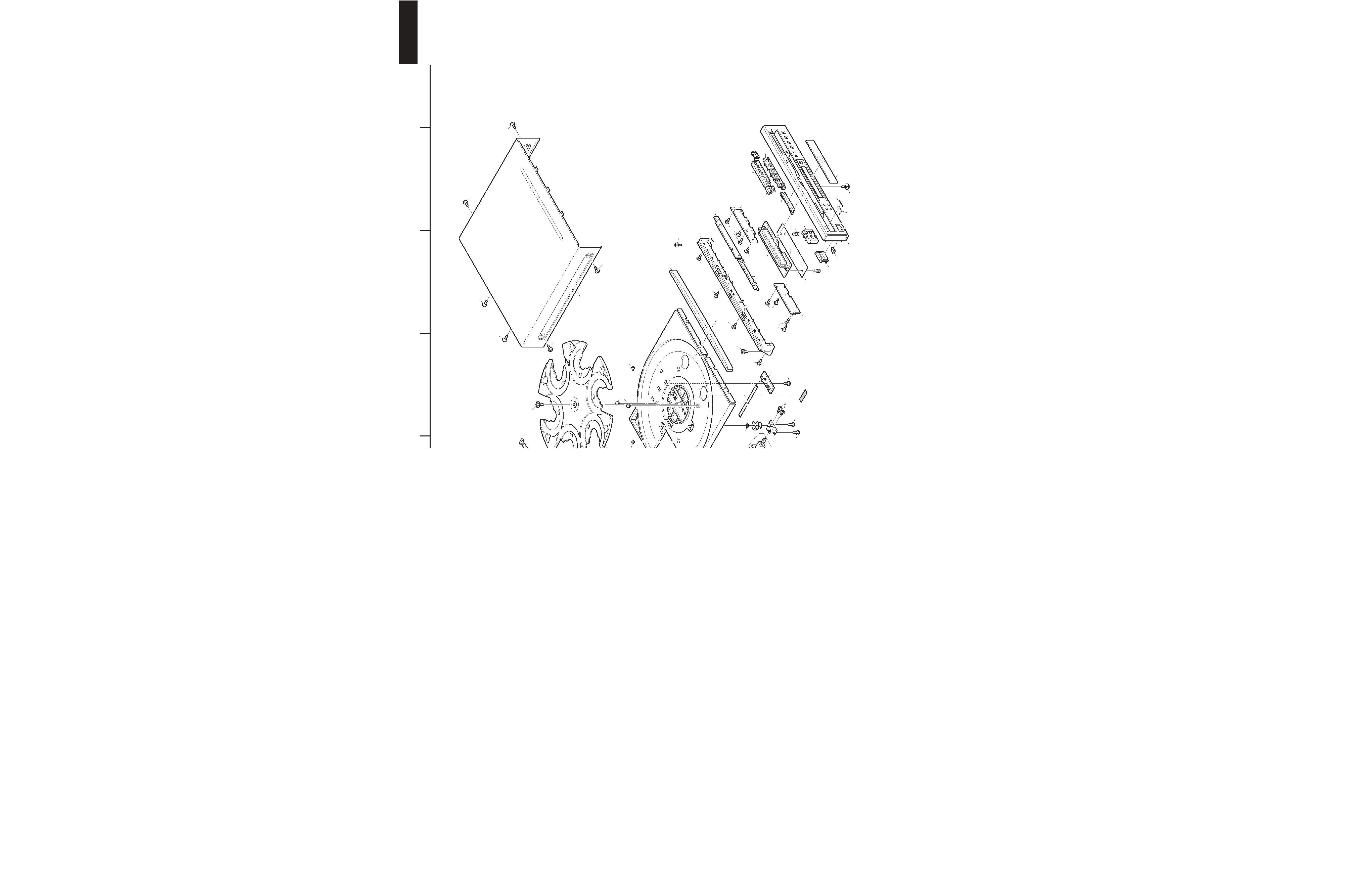
DV-CP701
EXPLODED VIEW
A
1
2
3
4
5
B
C
DE
FG
H
3
2
5
6
4
1
A22
A22
A19
A19
A19
A19
A19
A25
A26
A30
A31
A32
A33
A25
A25
A25
A25
A25
A25
A25
A26
A26
A26
A25
A26
A25
A25
A41
A41
A42
A42
A42
A42
A46
A46
A48
A50
A53
A54
A54
A54
A56
A214
A215
A215
A215
A215
A215
A215
E102
F001
A25
P901
U1
U2
U14
E821
A25
A25
A34
A25
M01
M02
M06
M04
M07
M08
M09
M10
M11
M11
M11
M12
M13
M14
M14
M15
M15
P1101
M16
M11
M11
P1001
M17
M18
M19
M50
M32
M35
M36
A26
A26
(U8)
A19
A19
(U7)
A19
A19
(U6)
(U9)
(U12)
P707
(U3)
P2501
P2901
A25
P2401
P2001
A54
Cloth tape
(160)
Cloth
tape
(80)
Cloth tape
M11
A25
A59
A32
A15
A15
A15
A25
M41
M42
b
a
b
a
c
c
d
d
e
f
e
f
A25
e
e
A01
A02
A03
A04
A05
A06
A08
A12
A13
A14
A18
A21
M38
M38
M38
M39
A07
<S> only
Cloth tape
(80)
P702