S400
RDS FM Tuner
Owner's Manual
GB
Manuel d'Installation
F
Bedienungsanleitung
D
Manual del Usuario
E
Manuale delle Istruzioni
I
Manual do Proprietário
P
Bruksanvisning
S
Warning: To reduce the risk of fire or electric shock, do not
expose this unit to rain or moisture.
The lightning flash with an arrowhead symbol within an equilateral
triangle, is intended to alert the user to the presence of uninsulated
"dangerous voltage" within the product's enclosure that may be of
sufficient magnitude to constitute a risk of electric shock to persons.
The exclamation point within an equilateral triangle is intended to
alert the user to the presence of important operating and
maintenance (servicing) instructions in the literature accompanying
the product.
Do not place this unit on an unstable cart, stand or tripod, bracket
or table. The unit may fall, causing serious injury to a child or adult
and serious damage to the unit. Use only with a cart, stand, tripod,
bracket or table recommended by the manufacturer or sold with
the unit. Any mounting of the device on a wall or ceiling should
follow the manufacturer's instructions and should use a mounting
accessory recommended by the manufacturer.
An appliance and cart combination should be moved with care.
Quick stops, excessive force and uneven surfaces may cause the
appliance and cart combination to overturn.
Read and follow all the safety and operating instructions before
connecting or using this unit. Retain this notice and the owner's
manual for future reference.
All warnings on the unit and in its operating instructions should be
adhered to.
Do not use this unit near water; for example, near a bath tub,
washbowl, kitchen sink, laundry tub, in a wet basement or near a
swimming pool.
The unit should be installed so that its location or position does not
interfere with its proper ventilation. For example, it should not be
situated on a bed, sofa, rug or similar surface that may block the
ventilation openings; or placed in a built-in installation, such as a
bookcase or cabinet, that may impede the flow of air through its
ventilation openings.
The unit should be situated from heat sources such as radiators,
heat registers, stoves or other devices (including amplifiers) that
produce heat.
The unit should be connected to a power supply outlet only of the
voltage and frequency marked on its rear panel.
The power supply cord should be routed so that it is not likely to be
walked on or pinched, especially near the plug, convenience
receptacles, or where the cord exits from the unit.
Unplug the unit from the wall outlet before cleaning. Never use
benzine, thinner or other solvents for cleaning. Use only a soft
damp cloth.
The power supply cord of the unit should be unplugged from the
wall outlet when it is to be unused for a long period of time.
Care should be taken so that objects do not fall, and liquids are not
spilled into the enclosure through any openings.
This unit should be serviced by qualified service personnel when:
A. The power cord or the plug has been damaged; or
B. Objects have fallen, or liquid has been spilled into the unit; or
C. The unit has been exposed to rain or liquids of any kind; or
D. The unit does not appear to operate normally or exhibits a
marked change in performance; or
E. The device has been dropped or the enclosure damaged.
DO NOT ATTEMPT SERVICING OF THIS UNIT
YOURSELF. REFER SERVICING TO QUALIFIED
SERVICE PERSONNEL
Upon completion of any servicing or repairs, request the service
shop's assurance that only Factory Authorized Replacement Parts
with the same characteristics as the original parts have been used,
and that the routine safety checks have been performed to
guarantee that the equipment is in safe operating condition.
REPLACEMENT WITH UNAUTHORIZED PARTS MAY RESULT IN FIRE,
ELECTRIC SHOCK OR OTHER HAZARDS.
ATTENTION
POUR ÉVITER LES CHOC ELECTRIQUES, INTRODUIRE LA
LAME LA PLUS LARGE DE LA FICHE DANS LA BORNE
CORRESPONDANTE DE LA PRISE ET POUSSER JUSQU'AU
FOND.
CAUTION
TO PREVENT ELECTRIC SHOCK, MATCH WIDE BLADE OF
PLUG TO WIDE SLOT FULLY INSERT.
If an indoor antenna is used (either built into the set or installed
separately), never allow any part of the antenna to touch the metal
parts of other electrical appliances such as a lamp, TV set etc.
CAUTION
POWER LINES
Any outdoor antenna must be located away from all power lines.
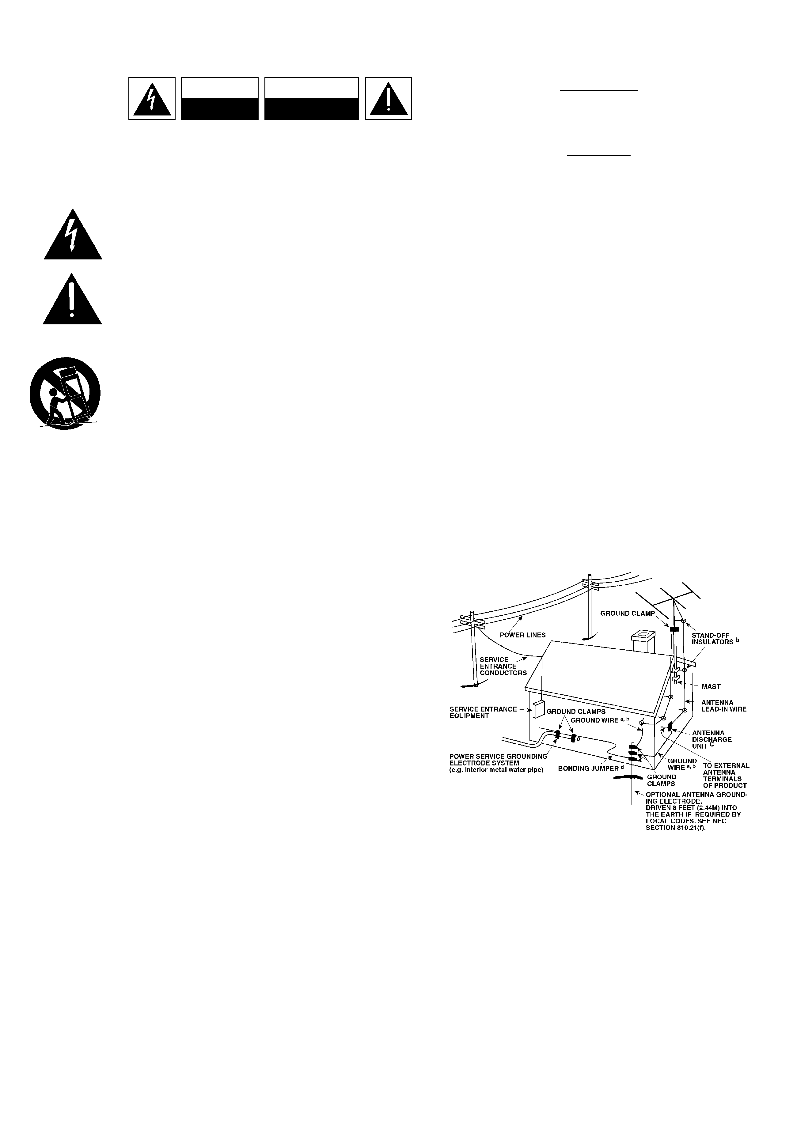
OUTDOOR ANTENNA GROUNDING
If an outside antenna is connected to your tuner or tuner-
preamplifier, be sure the antenna system is grounded so as to
provide some protection against voltage surges and built-up static
charges. Article 810 of the National Electrical Code, ANSI/NFPA No.
70-1984, provides information with respect to proper grounding of
the mast and supporting structure, grounding of the lead-in wire to
an antenna discharge unit, size of grounding conductors, location of
antenna discharge unit, connection to grounding electrodes and
requirements for the grounding electrode.
a. Use No. 10 AWG (5.3mm2) copper, No. 8 AWG (8.4mm2)
aluminium, No. 17 AWG (1.0mm2) copper-clad steel or bronze
wire, or larger, as a ground wire.
b. Secure antenna lead-in and ground wires to house with stand-off
insulators spaced from 4-6 feet (1.22 - 1.83 m) apart.
c. Mount antenna discharge unit as close as possible to where lead-
in enters house.
d. Use jumper wire not smaller than No.6 AWG (13.3mm2) copper,
or the equivalent, when a separate antenna-grounding electrode
is used. see NEC Section 810-21 (j).
EXAMPLE OF ANTENNA GROUNDING AS PER NATIONAL ELECTRICAL
CODE INSTRUCTIONS CONTAINED IN ARTICLE 810 - RADIO AND
TELEVISION EQUIPMENT.
NOTE TO CATV SYSTEM INSTALLER: This reminder is
provided to call the CATV system installer's attention to
Article 820-40 of the National Electrical Code that provides
guidelines for proper grounding and, in particular, specifies
that the ground cable ground shall be connected to the
grounding system of the building, as close to the point of
cable entry as practical.
CAUTION
RISK OF ELECTRIC
SHOCK DO NOT OPEN
ATTENTION:
RISQUE DE CHOC ELECTRIQUE
NE PAS OUVRIR
CAUTION: TO REDUCE THE RISK OF ELECTRIC
SHOCK, DO NOT REMOVE COVER (OR BACK). NO
USER SERVICEABLE PARTS INSIDE. REFER SERVICING
TO QUALIFIED SERVICE PERSONNEL.
IMPORTANT SAFETY INSTRUCTIONS
2
3
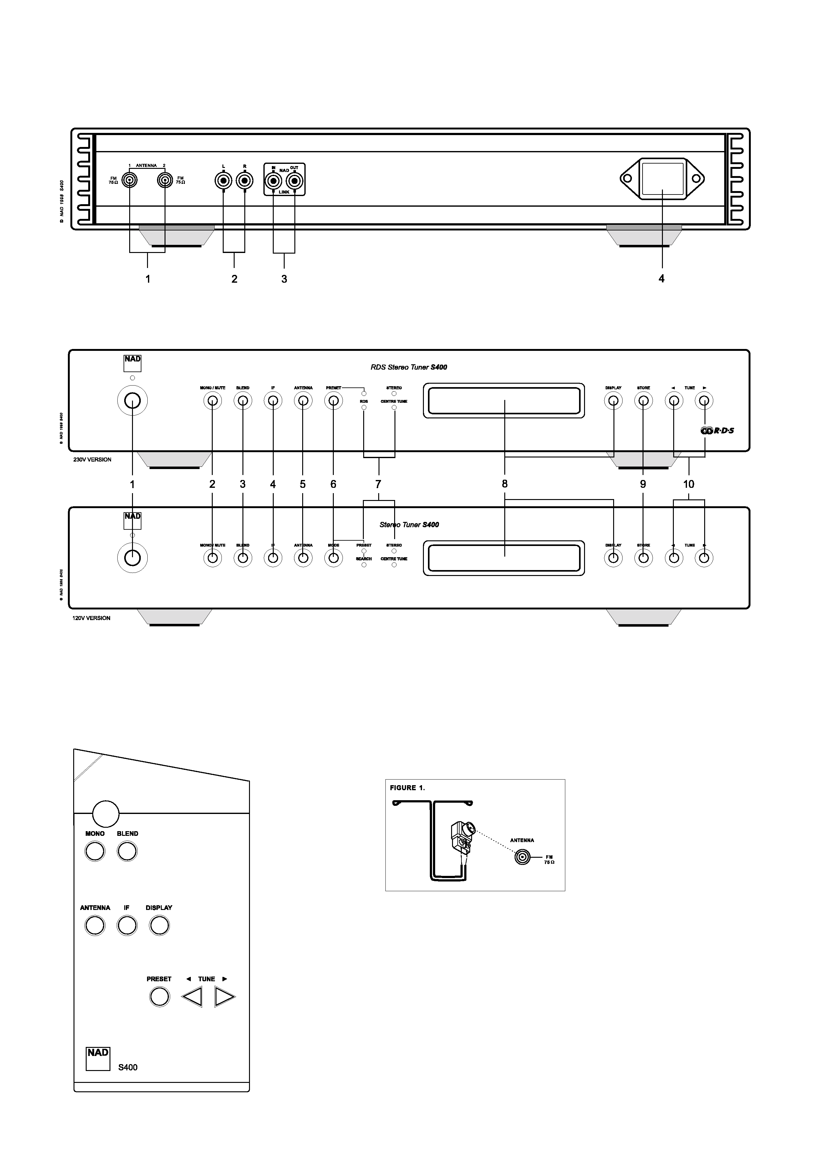
FRONT PANEL CONTROLS
REAR PANEL CONNECTIONS
REMOTE CONTROL

QUICK START
Use the RCA-to-RCA lead to connect the S400 left & right outputs to
the tuner inputs of your amplifier.
1. Plug in the AC Mains cable.
2. Connect FM antenna.
3. Connect S400 outputs to amplifier.
4. Press the POWER button to turn on the S400.
5. Select antenna input to which aerial is connected.
6. Press TUNE
or
for one second to activate Search mode.
7. When a station is found, search will stop.
NOTES ON INSTALLATION
Your S400 should be placed on a firm, level surface. Avoid placing
the unit in direct sunlight, near sources of heat and damp or in
poorly ventilated positions.
It comes with RCA leads for connection to your amplifier. Ensure that
leads and connectors are not damaged in any way and all connectors
are firmly pushed home.
If the unit is not going to be used for some time, disconnect the plug
from the AC socket.
Should water get into your S400, shut off the power to the unit
and remove the AC Mains cable from the AC socket. Have the
unit inspected by a qualified service technician before attempting
to use it again.
Do not open the tuner or attempt to modify or repair it
yourself. Refer all servicing to a qualified technician. Do not
remove the cover, there are no user-serviceable parts inside.
Use a dry soft cloth to clean the unit. If necessary, lightly dampen the
cloth with soapy water. Do not use solutions containing benzol or
other volatile agents.
REAR PANEL CONNECTIONS
1. FM ANTENNA
The S400 is equipped with two antenna connectors to allow you to
connect simultaneously to for example a cable network and an
outdoor aerial.
A ribbon wire FM antenna is included in order to permit reception
even if no outdoor antenna or cable is available. It should be
connected to one of the FM connectors at the rear of the unit using
the `balun' adapter supplied. See Figure 1.
The ribbon aerial should be mounted on a vertical surface and placed
so that it forms a `T'. Experiment with placement of the indoor
antenna to find the position that gives the best signal strength and
lowest background noise. An inadequate FM signal normally results
in high levels of hiss, especially in stereo, and interference from
external electrical sources. In areas of poor FM reception, the tuner
performance can be improved by using an externally mounted FM
antenna. A qualified aerial installer will be able to advise and fit a
recommended aerial for your reception conditions.
2. OUTPUT
Using twin RCA-to-RCA leads, connect the Left (white) and Right
(red) audio outputs to the `Tuner' input or other line-level input such
as `Aux' input of your amplifier.
3. NAD-LINK IN/OUT
The NAD-Link connector is used to pass commands from other units
fitted with NAD-Link connectors. This allows centralised control of a
complete system, and also allows some of the basic functions of the
S400 to be controlled using a NAD-Linked amplifier's remote control
or gives system control from more than one room. To function with
such other units, connect the Tuner's NAD-Link IN to the NAD-Link
OUT on the other unit. NAD-Link connectors can be daisy-chained,
IN to OUT, so that a whole system can be controlled from the remote
control facilities of one unit.
4. IEC AC MAINS INPUT
The S400 comes supplied with a separate AC mains cable. Before
connecting the cable to a live wall socket, ensure that it is firmly
connected to the NAD S400's AC Mains input socket first. Always
disconnect the AC mains cable plug from the live wall socket first
before disconnecting the cable from the S400 Mains input socket.
FRONT PANEL CONTROLS
1. POWER ON/OFF
Press this button to switch on the power to the S400. Press again
and release to switch the power off. The display window lights up
when power is ON. The blue LED above the POWER button lights up
briefly when ON/OFF is activated, but it goes out again immediately.
The blue LED lights up permanently only to indicate stand-by if the
unit is turned off from an NAD system remote control with STANDBY
button. If this option is used, the S400 may be switched on again by
pressing the STANDBY button of the system remote, or by pressing
and releasing the POWER button on the front of the S400 to switch
it off, and then press it again to switch it on. Please note that the
remote control which comes with the S400 does not feature a
STANDBY button.
The S400 uses a non-volatile memory to store preset information.
This information is retained even if the unit is switched off
completely or unplugged.
NOTE: When switching power On, the S400 will go back to the
station last tuned to before the unit was turned off. This will allow
you to make timer recordings using an external timer and recorder.
2. MONO/MUTE
Switches between Stereo mode with Muting (Mute) on and Mono
mode with Muting off. Muting suppresses stations that are too weak
to be received well. If Muting is switched off, even very weak
stations may be heard. As these will always be too weak for stereo
reception, Mono is activated simultaneously. The first press of the
button shows Mute On or Off as well as Stereo or Mono in the
display panel. Press Mute again within approx. five seconds to turn
Muting off (or on) and at the same time switch from stereo to mono.
GB
4
NAD S400 RDS FM Tuner

3. BLEND
High Blend is used for stations that are too remote or weak to permit
noise-free reception in stereo. In order to reduce noise and hiss, this
feature "blends" the stereo channels into mono within a narrow
audio frequency band, thereby reducing hiss considerably while still
maintaining good stereo separation. Pressing BLEND first shows the
status in the display panel. Pressing again within approx. five seconds
changes to ON or OFF.
4. IF
Intermediate Frequency control. Changes the IF between two values,
WIDE for the best possible sound quality and NARROW to remove
interference between stations that are very close to each other in
frequency. Pressing IF first shows the status in the display panel.
Pressing again within approx. five seconds changes to NARROW or
WIDE.
5. ANTENNA
Switches between one of the two antennas that may be connected
to the S400. Pressing ANTENNA first shows the status in the display
panel (Antenna 1 or 2). Pressing again within approx. five seconds
cycles between the two. Simultaneously, the signal strength for the
current antenna is shown as "S" and 0 to 9, where 0 is minimum or
no signal and 9 is maximum signal strength.
6. PRESET (230V VERSION)
OR MODE (120V VERSION)
The PRESET (or MODE) button switches between two ways of using
the TUNE buttons
or
.
Press the PRESET (or MODE) button until the "PRESET" LED lights up.
Press the
button to scroll to a lower number preset. Press the
button to scroll to a higher preset number. A total of 30 preset
memories are available. This is a "wrap-around" function, so that
going from the highest number preset the tuner will go to the
lowest preset number when
is pressed.
Refer to section 10. STORING AND RECALLING PRESETS.
NOTE: In the 120V North America version of the S400, which is not
equipped with RDS, the PRESET button is named MODE. It switches
between the Preset and Search functions indicated by the PRESET
and SEARCH LED's lighting up alternately.
7. LED INDICATORS
The PRESET indicator is explained under section 6. PRESET.
The RDS indicator lights up when a station broadcasting RDS data is
received.
The SEARCH indicator lights up (in 120V version only) when the
S400 is in Search mode.
The STEREO indicator lights up when the S400 receives a stereo
broadcast.
The CENTRE TUNE indicator lights up when the S400 is tuned to the
exact frequency of the transmitter.
8. DOT MATRIX DISPLAY AND DISPLAY BUTTON
The display is the centre of information. It is controlled by the
DISPLAY button, which allows you to read out various details about
the broadcasts.
1. When the S400 is switched on, the display shows the frequency,
the signal strength and the Preset number (if any).
2. After 3 seconds, the display switches to RDS station name and
frequency, or manually entered name. If there is no RDS data or
name, the display remains as a).
3. If the DISPLAY button is pressed, the display shows RADIO TEXT if
the station features this.
4. Pressing the DISPLAY button once more changes back to 1.
5. If the DISPLAY button is pressed and held down, the display will
scroll through the above information followed by all setup details
for Mute, IF, Antenna and Blend. Each line is shown for 2 seconds.
9. STORE
The STORE button is used to store stations into the Preset Memory.
Used in conjunction with the PRESET (or MODE) and TUNE buttons.
10. TUNE
AND
The function of these buttons depends on the tuning mode
indicated in the display panel.
In normal operation there are 2 modes:
a) Preset mode Press the PRESET (or MODE) button until the
"PRESET" LED lights up. See section 6. PRESET.
b) Search mode Press the PRESET(or MODE) button until the
"PRESET" LED extinguishes (or in 120V versions, until the SEARCH
LED lights up).
Now you can use the TUNE buttons
or
to engage
automatic or manual tuning up or down the frequency band.
Auto By keeping one of the TUNE buttons depressed for more than
approx. one second and then letting go, the tuner will search
automatically for the first reasonably strong radio station, where it
will stop. Press and hold the TUNE button again to start searching
again. If a stereo station is received, the "STEREO" LED will light
up.
Manual By tapping one of the TUNE buttons
or
rapidly,
you can perform manual tuning up or down the frequency band
for precise tuning to a specific frequency. With each successive tap
of the keys, the tuner will take 0.025MHz steps on so you can
accurately tune into the desired frequency. This tuning mode can
also be useful when trying to receive a radio station, which is too
weak for the Search mode.
GB
5