S200
Stereo Power Amplifier
Owner's Manual
GB
Manuel d'Installation
F
Bedienungsanleitung
D
Manual del Usuario
E
Manuale delle Istruzioni
I
Manual do Proprietário
P
Bruksanvisning
S
Warning: To reduce the risk of fire or electric shock, do not
expose this unit to rain or moisture.
The lightning flash with an arrowhead symbol within an equilateral
triangle, is intended to alert the user to the presence of uninsulated
"dangerous voltage" within the product's enclosure that may be of
sufficient magnitude to constitute a risk of electric shock to persons.
The exclamation point within an equilateral triangle is intended to
alert the user to the presence of important operating and
maintenance (servicing) instructions in the literature accompanying
the product.
Do not place this unit on an unstable cart, stand or tripod, bracket
or table. The unit may fall, causing serious injury to a child or adult
and serious damage to the unit. Use only with a cart, stand, tripod,
bracket or table recommended by the manufacturer or sold with
the unit. Any mounting of the device on a wall or ceiling should
follow the manufacturer's instructions and should use a mounting
accessory recommended by the manufacturer.
An appliance and cart combination should be moved with care.
Quick stops, excessive force and uneven surfaces may cause the
appliance and cart combination to overturn.
Read and follow all the safety and operating instructions before
connecting or using this unit. Retain this notice and the owner's
manual for future reference.
All warnings on the unit and in its operating instructions should be
adhered to.
Do not use this unit near water; for example, near a bath tub,
washbowl, kitchen sink, laundry tub, in a wet basement or near a
swimming pool.
The unit should be installed so that its location or position does not
interfere with its proper ventilation. For example, it should not be
situated on a bed, sofa, rug or similar surface that may block the
ventilation openings; or placed in a built-in installation, such as a
bookcase or cabinet, that may impede the flow of air through its
ventilation openings.
The unit should be situated from heat sources such as radiators,
heat registers, stoves or other devices (including amplifiers) that
produce heat.
The unit should be connected to a power supply outlet only of the
voltage and frequency marked on its rear panel.
The power supply cord should be routed so that it is not likely to be
walked on or pinched, especially near the plug, convenience
receptacles, or where the cord exits from the unit.
Unplug the unit from the wall outlet before cleaning. Never use
benzine, thinner or other solvents for cleaning. Use only a soft
damp cloth.
The power supply cord of the unit should be unplugged from the
wall outlet when it is to be unused for a long period of time.
Care should be taken so that objects do not fall, and liquids are not
spilled into the enclosure through any openings.
This unit should be serviced by qualified service personnel when:
A. The power cord or the plug has been damaged; or
B. Objects have fallen, or liquid has been spilled into the unit; or
C. The unit has been exposed to rain or liquids of any kind; or
D. The unit does not appear to operate normally or exhibits a
marked change in performance; or
E. The device has been dropped or the enclosure damaged.
DO NOT ATTEMPT SERVICING OF THIS UNIT
YOURSELF. REFER SERVICING TO QUALIFIED
SERVICE PERSONNEL
Upon completion of any servicing or repairs, request the service
shop's assurance that only Factory Authorized Replacement Parts
with the same characteristics as the original parts have been used,
and that the routine safety checks have been performed to
guarantee that the equipment is in safe operating condition.
REPLACEMENT WITH UNAUTHORIZED PARTS MAY RESULT IN FIRE,
ELECTRIC SHOCK OR OTHER HAZARDS.
ATTENTION
POUR ÉVITER LES CHOC ELECTRIQUES, INTRODUIRE LA
LAME LA PLUS LARGE DE LA FICHE DANS LA BORNE
CORRESPONDANTE DE LA PRISE ET POUSSER JUSQU'AU
FOND.
CAUTION
TO PREVENT ELECTRIC SHOCK, MATCH WIDE BLADE OF
PLUG TO WIDE SLOT FULLY INSERT.
If an indoor antenna is used (either built into the set or installed
separately), never allow any part of the antenna to touch the metal
parts of other electrical appliances such as a lamp, TV set etc.
CAUTION
POWER LINES
Any outdoor antenna must be located away from all power lines.
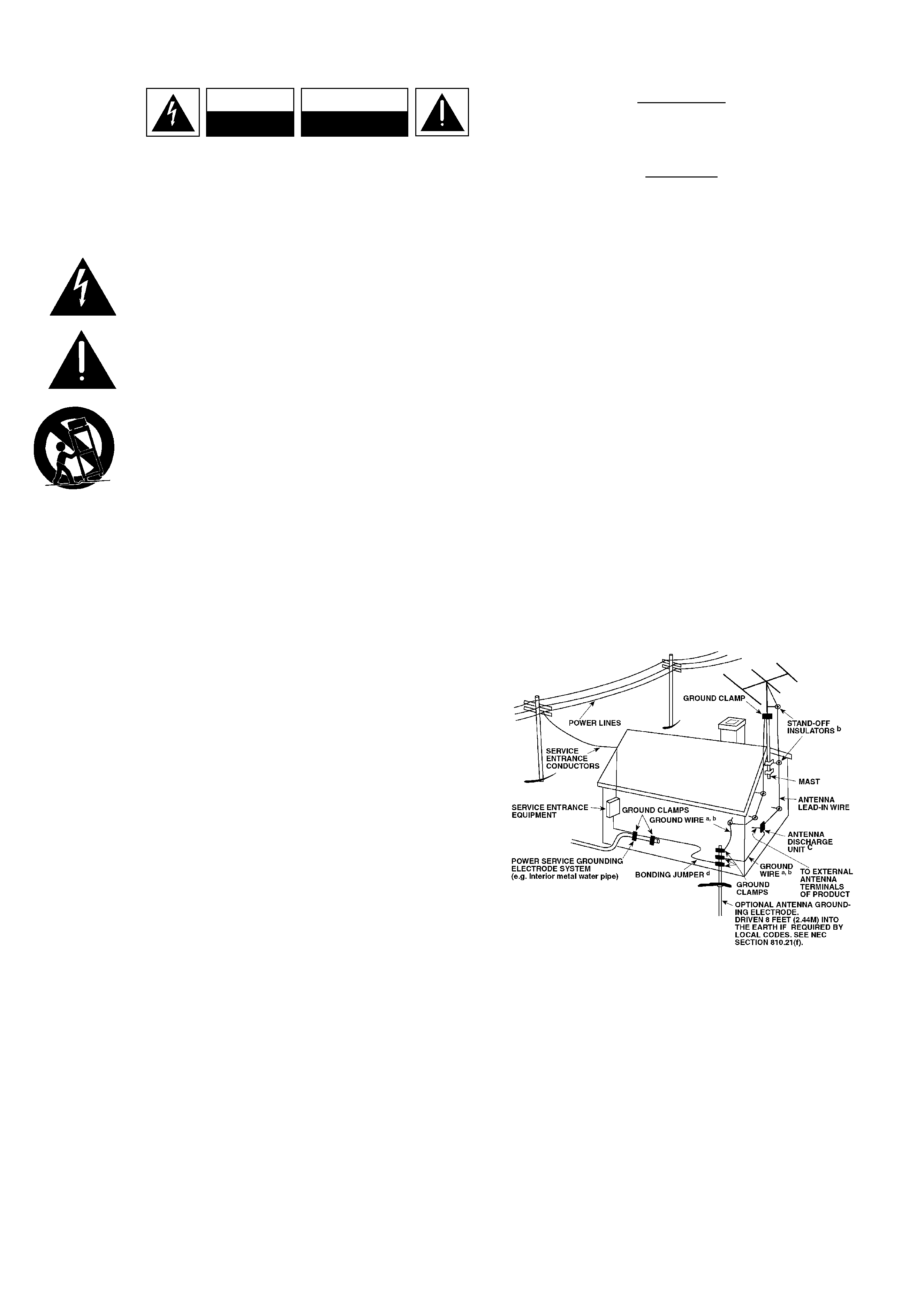
OUTDOOR ANTENNA GROUNDING
If an outside antenna is connected to your tuner or tuner-
preamplifier, be sure the antenna system is grounded so as to
provide some protection against voltage surges and built-up static
charges. Article 810 of the National Electrical Code, ANSI/NFPA No.
70-1984, provides information with respect to proper grounding of
the mast and supporting structure, grounding of the lead-in wire to
an antenna discharge unit, size of grounding conductors, location of
antenna discharge unit, connection to grounding electrodes and
requirements for the grounding electrode.
a. Use No. 10 AWG (5.3mm2) copper, No. 8 AWG (8.4mm2)
aluminium, No. 17 AWG (1.0mm2) copper-clad steel or bronze
wire, or larger, as a ground wire.
b. Secure antenna lead-in and ground wires to house with stand-off
insulators spaced from 4-6 feet (1.22 - 1.83 m) apart.
c. Mount antenna discharge unit as close as possible to where lead-
in enters house.
d. Use jumper wire not smaller than No.6 AWG (13.3mm2) copper,
or the equivalent, when a separate antenna-grounding electrode
is used. see NEC Section 810-21 (j).
EXAMPLE OF ANTENNA GROUNDING AS PER NATIONAL ELECTRICAL
CODE INSTRUCTIONS CONTAINED IN ARTICLE 810 - RADIO AND
TELEVISION EQUIPMENT.
NOTE TO CATV SYSTEM INSTALLER: This reminder is
provided to call the CATV system installer's attention to
Article 820-40 of the National Electrical Code that provides
guidelines for proper grounding and, in particular, specifies
that the ground cable ground shall be connected to the
grounding system of the building, as close to the point of
cable entry as practical.
CAUTION
RISK OF ELECTRIC
SHOCK DO NOT OPEN
ATTENTION:
RISQUE DE CHOC ELECTRIQUE
NE PAS OUVRIR
CAUTION: TO REDUCE THE RISK OF ELECTRIC
SHOCK, DO NOT REMOVE COVER (OR BACK). NO
USER SERVICEABLE PARTS INSIDE. REFER SERVICING
TO QUALIFIED SERVICE PERSONNEL.
IMPORTANT SAFETY INSTRUCTIONS
2
3
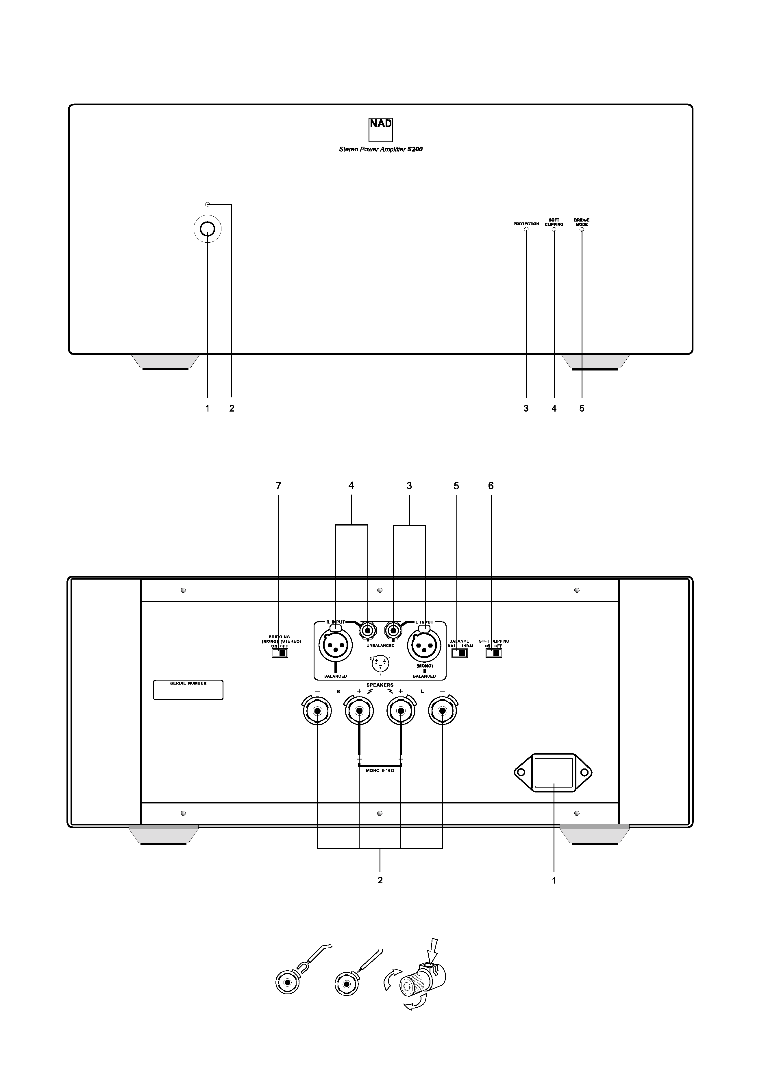
FRONT PANEL CONTROLS
REAR PANEL CONNECTIONS
FIGURE 1
©1998
NAD
S200
©1998
NAD
S200

GB
4
NAD S200 Stereo Power Amplifier
NOTES ON INSTALLATION
This unit may be installed on any level surface that is strong enough
to support its weight. Since its power transformer generates a
significant magnetic hum field, a turntable (especially one with a
moving-coil pick-up cartridge) or a TV should not be located adjacent
to the amplifier or directly above it.
The heat-sink fins make it awkward to lift the S200 by grasping the
left and right sides. You may find it more practical to place your
hands under the front and rear panels. Much of the amplifier's
weight is near the front panel.
CAUTION: The amplifier's weight must always rest on its bottom feet.
Never put the amplifier down on its rear panel, with its front panel
facing up. Doing so risks damage to the input/output connectors.
The amplifier generates a moderate amount of heat, requiring
internal ventilation. Do not permit the air outlet grille on the top
cover to be obstructed by papers or articles of clothing. If you want
to locate the amplifier on a carpeted floor, place a board under the
amplifier in order to prevent it from sinking into the carpet, blocking
the air inlets on its bottom.
CAUTION: To prevent a fire or shock hazard, do not permit liquid or
moisture to enter the amplifier. If liquid is accidentally spilled on it,
immediately shut off the power and unplug the AC Mains cable
from the wall outlet.
Do not open the amplifier or attempt to modify or repair it
yourself. Refer all servicing to a qualified technician.
REAR PANEL CONNECTIONS
1. IEC AC MAINS (POWER) INPUT
The NAD S200 comes supplied with a separate AC Mains cable.
Before connecting the cable to a live wall socket ensure that it is
firmly connected to the S200's AC Mains input socket first. Always
disconnect the AC Mains cable plug from the live wall socket first,
before disconnecting the cable from the S200 Mains input socket.
Plug the AC Mains cable into a live wall socket. If you must use an
extension cord, select a heavy-duty cord of the type used for large
electrical appliances.
Do not connect the amplifier's Mains cable to the accessory AC outlets
on a preamplifier. Such convenience outlets are not designed to supply
the high power levels, up to 800 watts, that the S200 requires. If you
wish to switch your entire audio system on and off at once, plug both
the S200 and your preamplifier into a "power strip" containing several
grounded AC outlets and a high-current on/off switch.
Voltage conversion. A notice printed on the rear indicates the AC
power-line voltage that the amplifier requires. However, every model
S200 amplifier has a "universal" power supply that can be modified
easily for operation in other countries. If you wish to transport your
S200 to a nation that employs a different power-line voltage, an
authorised NAD dealer or service agency can convert it for such use.
2. SPEAKERS
This amplifier is equipped with special high-current binding post
speaker terminals to handle the highest peak power levels that may
occur in the "bridged" mode or with low-impedance speakers. At
moments when the amplifier is producing maximum power, voltages
of nearly 100 V may be present on the speaker terminals, so the
terminals are protected by transparent plastic covers.
To connect loudspeaker cables, first switch off the amplifier's power.
If you are connecting a pair of speakers for normal stereo operation,
be sure that the bridging switch is set to OFF (STEREO).
For best stereo imaging, the left and right speakers should be located
at equal distances from your chair. To minimise the effect of speaker
cables on the sound, locate the amplifier near the speakers and use
short cables to connect the speakers. If your preamplifier is located at
the opposite end of the room near your chair, you will need a long
cable to connect it to the power amplifier. All NAD preamplifiers have
the low output impedance required to drive long connecting cables.
Connect the wires from your left channel speaker to the (L+) and (L-)
terminals on the rear panel of the S200, and connect the wires from
the right channel speaker to the (R+) and (R-) terminals. In each
channel, the red terminal is the positive (+) output, and the black
terminal is the negative (-) or "ground" terminal.
Use heavy duty (16-gauge/2 sq.mm or thicker) wire, especially with 4
ohm loudspeakers. Bare wires can be connected directly to the
binding post terminals. For a longer lasting and more corrosion
resistant connection, you may purchase speaker cables with gold
plated connectors (pin connectors or spade lugs), or you can install
such connectors on the wires yourself. Connections to each binding
post may be made in several ways as follows. (See Figure 1.)
1. Pin connectors. A pin connector is a slim metal shaft that is crimped
or soldered onto the end of a wire. The threaded shaft of each
binding post contains an opening that accepts pin connectors up
to 3mm in diameter. Unscrew the plastic bushing on each terminal
to expose the hole in the metal shaft. Insert the pin connector
through the hole, and turn the bushing clockwise until it is tight.
2. Spade lugs. Unscrew the plastic bushing, insert the U-shaped spade
lug into the oblong gap and tighten the bushing down on it.
3. Bare wires. Separate the two conductors of the cord (if they appear
as a pair), and strip off a half-inch (1cm) of insulation from each. In
each conductor, twist together the exposed wire strands. Unscrew
the plastic bushings for + and -, insert the bare wire through the
hole in the metal shaft, and tighten the plastic bushing until it
grasps the wire securely. Check to be sure that no loose strand of
wire is touching the chassis or an adjacent terminal. Re-tighten the
bushing after a week or so to make sure that any play that may
have developed is eliminated.

CAUTION: Safety organisations recommend that the speaker
terminals of a very powerful amplifier should be covered. Potentially
dangerous voltages are present on these terminals when the
amplifier is producing maximum power. For your protection and in
order to comply with these regulations, we have chosen speaker
terminals of the very highest quality for the NAD S200. These
terminals are covered by plastic bushings which prevent the touching
of metal parts.
PHASING
Stereo speakers must operate "in phase" with each other to produce
a focused stereo image and to reinforce rather than cancel each
other's output at low frequencies. An in-phase connection is assured
if the red (positive) terminal on the amplifier is connected to the red
(positive) terminal on the loudspeaker in each channel.
If your speakers are easily moved, their phasing can easily be checked.
Make the connections to both speakers, place the speakers face-to-
face only a few inches apart, play some music, and listen. Then swap
the connection of the two wires at the back of ONE of the speakers,
and listen again. The connection which produces the fullest, boomiest
bass output is the correct one. Connect the wires securely to the
speaker terminals, being careful not to leave any loose strands of wire
that might touch the wrong terminal and create a partial short-circuit
then move the speakers to their intended locations.
If the speakers cannot easily be set face-to-face, then phasing must
rely on the "polarity" of the connecting wires. The speaker terminals
on the amplifier are identified as red (+) and black (-) in each
channel. The terminals at the rear of the speakers are also marked
for polarity, either via red and black connectors or by labels: "+",
"1", or "8 ohms" for positive, "-", "0", or "G" for negative. The
red (+) terminal on the amplifier should be connected to the red
(positive) terminal of the speaker in each channel.
To facilitate this, the two conductors comprising the speaker wire in
each channel are different, either in the colour of the wire itself
(copper vs. silver) or in the presence of a small ridge or rib pattern on
the insulation of one conductor. Use this pattern to establish
consistent wiring to both speakers of a stereo pair. Thus if you
connect the copper coloured wire (or ribbed insulation) to the (+)
amplifier terminal in the Left channel, do the same in the Right
channel. At the other end of the wire, if you connect the copper
coloured wire (or the ribbed insulation) to the red or positive terminal
on the left channel speaker, do the same at the right channel speaker.
3. LEFT CHANNEL INPUTS
(BALANCED/UNBALANCED)
Before making or changing input connections to the amplifier, make
certain that the Power is Off.
The S200 amplifier is equipped with two input connectors for each
channel. The RCA phono jack is a conventional "unbalanced" input.
The three-hole XLR socket is a professional "balanced" input. You
may use either type of input, but not both.
If your preamplifier has only conventional outputs with RCA phono
jacks, connect an audio connecting cable from the left channel
output of the preamplifier to the left channel UNBALANCED input of
the S200. Set the BALANCE switch to UNBAL.
If your preamplifier has balanced XLR outputs, connect a three-
conductor cable from your left channel preamplifier output to the
left-channel XLR input on the S200, and set the BALANCE switch to
BAL. If your audio dealer does not have the appropriate cables,
purchase balanced "microphone" cables from a shop that sells
professional recording equipment. The end of the cable that has a
"male" XLR plug (with three metal pins) should be connected to the
S200 amplifier. The end of the cable that has a "female" XLR socket
(with three holes) should be connected to your preamplifier.
An XLR plug is "keyed" so that it fits into the socket only one way. If
there is a set-screw in the barrel of the plug, align it with the top of
the connector. Push the plug fully into the XLR socket until it latches
in place.
The three pins of an XLR type ("Cannon") connector are numbered.
Pin 2 is the signal "hot" connection in the S200, Pin 2 is connected
directly to the center pin of the unbalanced RCA phono jack. Pin 3 is
the signal return (signal ground) connection. Pin 1 is the chassis earth
(ground), to which the shield of a balanced-wire cable is connected.
UNPLUGGING
The XLR socket has a latching feature that prevents the connector
from being pulled out by accident. Before disconnecting an input
cable, turn off the Power. Use one hand to press the latching tab
above the XLR socket while using the other hand to pull the XLR
plug out.
4. RIGHT CHANNEL INPUTS
(BALANCED/UNBALANCED)
Make connections to the right channel input in the same way that
you did for the left channel.
5. INPUT SELECT (BALANCED/UNBALANCED)
Set this switch to match your selection of input connector. Set to
UNBAL if you have connected a cable from your preamplifier to the
RCA phono input jacks. Set the switch to BAL if you are making
connections to the balanced XLR inputs.
Normally the choice of input connector is determined by the output
connectors on your preamplifier. If your preamplifier has balanced
outputs, use three-conductor cables equipped with XLR connectors.
If your preamplifier has only "unbalanced" connections with RCA
phono jacks, use the corresponding inputs on the S200.
GB
5