GB
F
D
E
I
S
P
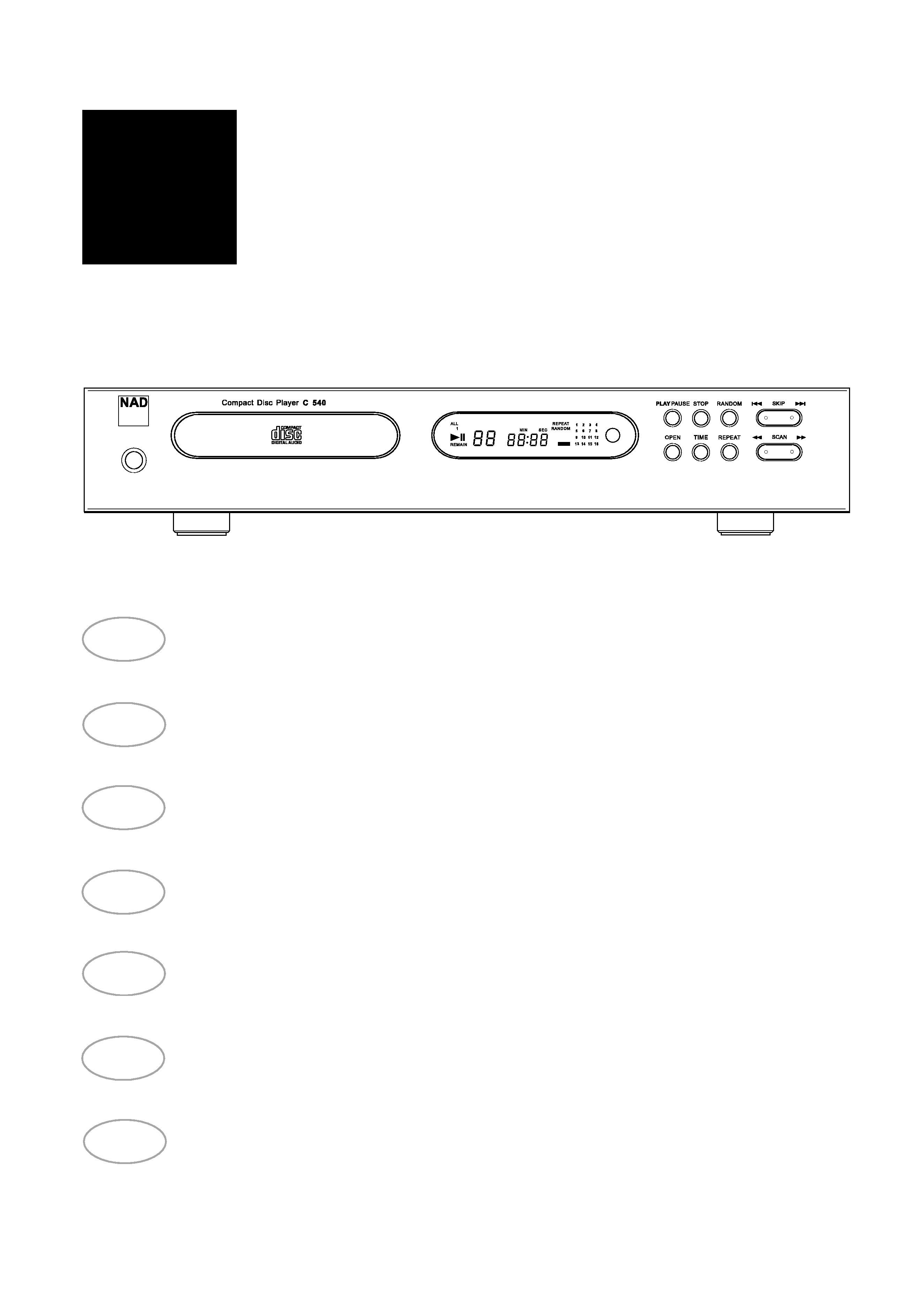
NAD
C 540
OVER
· OWNER'S MANUAL
· MANUEL D'INSTALLATION
· BEDIENUNGSANLEITUNG
· MANUAL DEL USUARIO
· MANUALE DELLE ISTRUZIONI
· BRUKSANVISNING
· MANUAL DO PROPRIETÁRIO
©1999
NAD
ELECTRONICS
LTD.
C540
NAD
2
Warning: To reduce the risk of fire or electric shock, do not expose this
unit to rain or moisture.
The lightning flash with an arrowhead symbol within an equilateral trian-
gle is intended to alert the user to the presence of uninsulated "dan-
gerous voltage" within the product's enclosure that may be of suffi-
cient magnitude to constitute a risk of electric shcok to persons.
The exclamation point within an equilateral triangle is intended to alert
the user to the presence of important operating and maintenance
(servicing) instructions in the literature accompanying the product.
Do not place this unit on an unstable cart, stand or tripod,
bracket or table. The unit may fall, causing serious injury to a
child or adult and serious damage to the unit. Use only with a
cart, stand, tripod, bracket or table recommended by the man-
ufacturer or sold with the unit. Any mounting of the device on a
wall or ceiling should follow the maufacturer's instructions and
should use a mounting accessory recommended by the manu-
facturer.
An appliance and cart combination should be moved with care. Quick stops,
excessive force and uneven surfaces may cause the appliance and cart combi-
nation to overturn.
Read and follow all the safety and operating instructions before connecting or
using this unit. Retain this notice and the owner's manual for future reference.
All warnings on the unit and in it's operating instructions should be adhered to.
Do not use this unit near water; for example, near a bath tub, washbowl, kitchen
sink, laundry tub, in a wet basement or near a swimming pool.
The unit should be installed so that its location or position does not interfere with
its proper ventilation. For example, it should not be situated on a bed, sofa, rug
or similar surface that may block the ventilation openings; or placed in a built-in
installation, such as a bookcase or cabinet, that may impede the flow of air
through its ventilation openings.
The unit should be situated from heat sources such as radiators, heat registers,
stoves or other devices (including amplifiers) that produce heat.
The unit should be connected to a power supply outlet only of the voltage and
frequency marked on its rear panel.
The power supply cord should be routed so that it is not likely to be walked on or
pinched, especially near the plug, convenience receptacles, or where the cord
exits from the unit.
Unplug the unit from the wall outlet before cleaning. Never use benzine, thinner
or other solvents for cleaning. Use only a soft damp cloth.
The power supply cord of the unit should be unplugged from the wall outlet when
it is to be unused for a long period of time.
Care should be taken so that objects do not fall, and liquids are not spilled into
the enclosure through any openings.
This unit should be serviced by qualified service personnel when:
A. The power cord or the plug has been damaged; or
B. Objects have fallen, or liquid has been spilled into the unit; or
C. The unit has been exposed to rain or liquids of any kind; or
D. The unit does not appear to operate normally or exhibits a marked change in
performance; or
E. The device has been dropped or the enclosure damaged.
DO NOT ATTEMPT SERVICING OF THIS UNIT YOURSELF.
REFER SERVICING TO QUALIFIED SERVICE
PERSONNEL.
Upon completion of any servicing or repairs, request the service shop's assur-
ance that only Factory Authorized Replacement Parts with the same characteris-
tics as the original parts have been used, and that the routine safety checks
have been performed to guarantee that the equipment is in safe operating condi-
tion.
REPLACEMENT WITH UNAUTHORIZED PARTS MAY RESULT IN FIRE,
ELECTRIC SHOCK OR OTHER HAZARDS.
ATTENTION
POUR ÉVITER LES CHOC ELECTRIQUES, INTRODUIRE LA LAME
LA PLUS LARGE DE LA FICHE DANS LA BORNE CORRESPON-
DANTE DE LA PRISE ET POUSSER JUSQU'AU FOND.
CAUTION
TO PREVENT ELECTRIC SHOCK MATCH WIDE BLADE OF PLUG
TO WIDE SLOT FULLY INSERT.
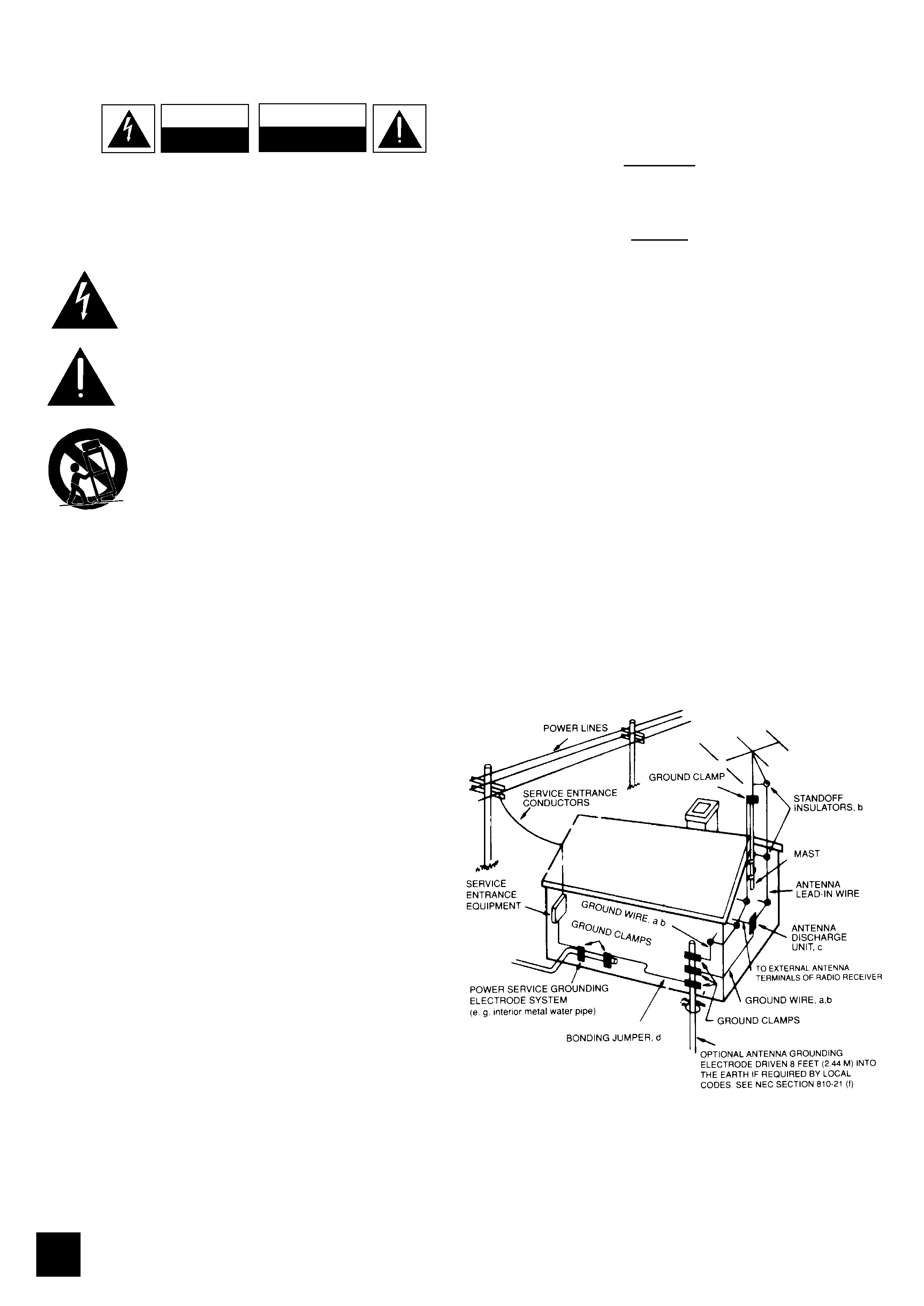
If an indoor antenna is used (either built into the set or installed separately),
never allow any part of the antenna to touch the metal parts of other electrical
appliances such as a lamp, TV set etc.
CAUTION
POWER LINES
Any outdoor antenna must be located away from all power lines.
OUTDOOR ANTENNA GROUNDING
If an outside antenna is connected to your tuner or tuner-preamplifier, be sure
the antenna system is grounded so as to provide some protection against volt-
age surges and built-up static charges. Section 810 of the National Electrical
Code, ANSI/NFPA No. 70-1984, provides information with respect to proper
grounding of the mast and supporting structure, grounding of the lead-in wire to
an antenna discharge unit, size of grounding conductors, location of antenna dis-
charge unit, connection to grounding electrodes and requirements for the
grounding electrode.
a. Use No. 10 AWG (5.3mm2) copper, No. 8 AWG (8.4mm2) aluminium, No. 17
AWG (1.0mm2) copper-clad steel or bronze wire, or larger, as a ground wire.
b. Secure antenna lead-in and ground wires to house with stand-off insulators
spaced from 4-6 feet (1.22 - 1.83 m) apart.
c. Mount antenna discharge unit as close as possible to where lead-in enters
house.
d. Use jumper wire not smaller than No.6 AWG (13.3mm2) copper, or the equiva-
lent, when a separate antenna-grounding electrode is used. see NEC Section
810-21 (j).
EXAMPLE OF ANTENNA GROUNDING AS PER NATIONAL ELECTRICAL
CODE INSTRUCTIONS CONTAINED IN ARTICLE 810 - RADIO AND TELEVI-
SION EQUIPMENT.
NOTE TO CATV SYSTEM INSTALLER: This reminder is provided to
call the CATV system installer's attention to Article 820-22 of the
National Electrical Code that provides guidelines for proper grounding
and, in particular, specifies that the ground cable ground shall be con-
nected to the grounding system of the building, as close to the point of
cable entry as practical.
CAUTION
RISK OF ELECTRIC
SHOCK DO NOT OPEN
ATTENTION:
RISQUE DE CHOC ELECTRIQUE
NE PAS OUVRIR
CAUTION: TO REDUCE THE RISK OF ELECTRIC SHOCK,
DO NOT REMOVE COVER (OR BACK). NO USER
SERVICEABLE PARTS INSIDE. REFER SERVICING TO
QUALIFIED SERVICE PERSONNEL
IMPORTANT SAFETY INSTRUCTIONS
NAD
3
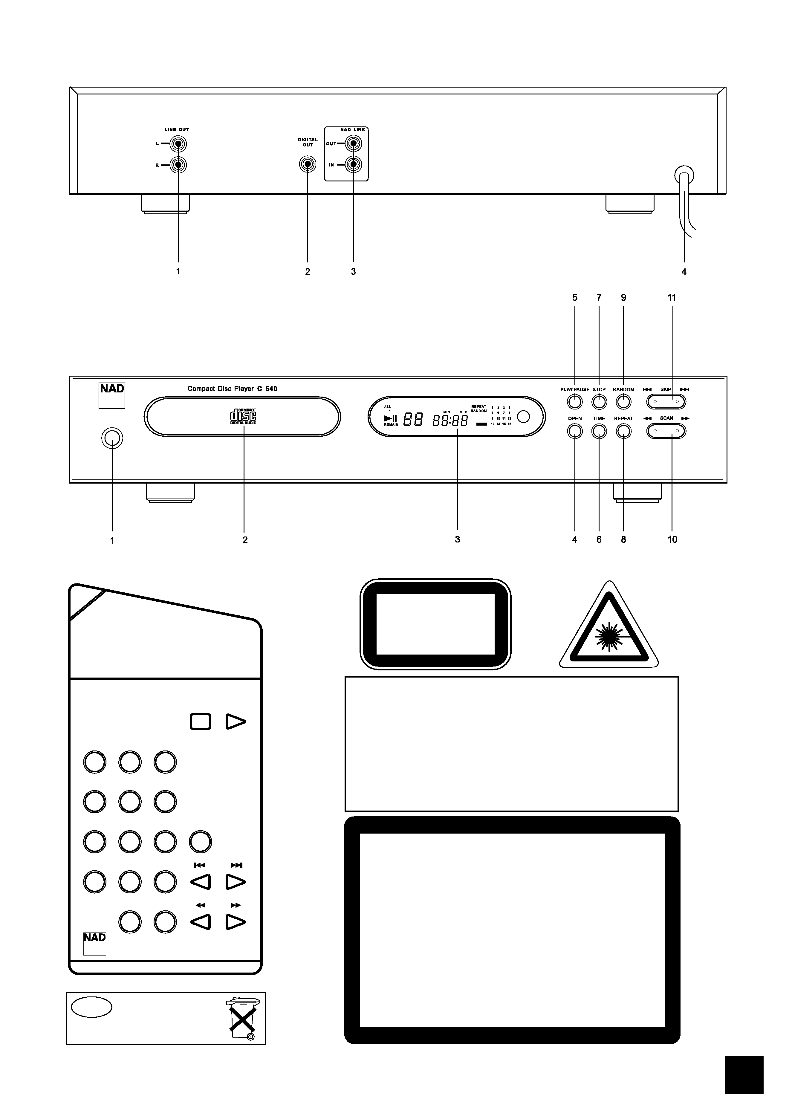
FRONT PANEL CONTROLS (Figure 2.)
STOP
123
456
789
TIME
10
0
+10
SKIP
REPEAT
RANDOM
SCAN
PLAY
PAUSE
CD1
REMOTE CONTROL
NL
Batterij niet
weggooien maar
inleveren als KCA
WARNING - INVISIBLE LASER RADIATION WHEN OPEN AND
INTERLOCKS DEFEATED. AVOID EXPOSURE TO BEAM.
VORSICHT! - UNSICHTBARE LASERTRAHLUNG TRITT AUS,
WENN DECKEL GEÖFFNET UND WENN SICHERHEITSVERRIEGELUNG
ÜBERBRÜCKT IST. NICHT DEM STRAHL AUSSETZEN.
ADVARSEL - USYNLIG LASERSTRÅLING VED ÅBNING, NÅR
SIKKERHEDSAFBRYDERE ER UDE AF FUNKTION. UNDGÅ
UDSÆTTELSE FOR STRÅLING.
ADVARSEL - USYNLIG LASERSTRALING NÅR DEKSEL ÅPNES OG
SIKKERHEDSLÅS BRYTES. UNNGÅ EKSPONERING FOR STRÅLEN.
VARING - OSYNLING LASERSTRÅLNING NÄR DENNA DEL ÄR
ÖPPNAD OCH SPÄRRAR ÄR URKOPPLADE. STRÅLEN ÄR FARLIG.
VARO! - AVATTAESSA JA SUOJALUKITUS OHITETTAESSA OLET
ALTTINA NÄKTMÄTONTÄ LASERSÄTEILYLLE. ÄLÄ KAISO SÄTEESEEN.
CLASS 1 LASER PRODUCT
LUOKAN 1 LASERPLAITE
KLASS 1 LASERAPPARAT
REAR PANEL CONNECTIONS (Figure 1.)
©1999.
NAD
ELECTRONICS
LTD.
C
540
OVER
©1999.
NAD
ELECTRONICS
LTD.
C
540
THIS DIGITAL APPARATUS DOES NOT EXCEED THE CLASS B
LIMITS FOR RADIO NOISE EMISSIONS FROM DIGITAL APPARA-
TUS AS SET OUT IN THE RADIO INTERFERENCE REGULATIONS
OF THE CANADIAN DEPARTMENT OF COMMUNICATIONS.
LE PRESENT APPAREIL NUMVERIQUE N'EMENT PAS DE
BRUITS RADIOELECTRIQUES DEPASSANT LES LIMITES
APPLICABLES AUX APPAREILS NUMERIQUES DE LA CALSSE B
PRESCRITES DANS LE REGLEMENT SUR LE BROUILLAGE
RADIO ELECTRIQUE EDICTE PAR LE MINISTERE DES COMMU-
NICATIONS DU CANADA.
SAFETY WARNING

INSTRUCTIONS FOR INSTALLATION
AND OPERATION
NOTE ON INSTALLATION
Install the Compact Disc player on a level, vibra-
tion-free surface. (Severe vibration, or operation in a
tilted position, may cause the player to mis-track.)
The player may be stacked with other stereo compo-
nents, as long as there is adequate ventilation around
it.
If the player is placed in close proximity to a radio
tuner (AM or FM), a VCR, or a television set, the
operation of its digital circuits may produce static that
would interfere with reception of weak broadcast sig-
nals. If this occurs, move the CD player away from
other devices or switch it off when viewing or listening
to broadcasts.
PLAYING COMPACT DISCS
A SIMPLE APPROACH
1. Connect a stereo cable from the L (left) and R
(right) Line Output jacks to the corresponding CD
inputs on your amplifier.
2. Plug in the AC power cord.
3. Press the green POWER button to turn on the
player.
4. Press OPEN to open the disc drawer.
5. Place a CD, label side up, in the tray's circular
recess. Be certain that the disc is centered within the
recess.
6. Press PLAY/PAUSE. The drawer closes auto-
matically, and the disc begins to play.
7. At any time you may press SKIP
or
to
select different tracks on the disc.
8. Press PLAY/PAUSE if you want to stop play
temporarily while keeping the pickup at its current
position on the disc. Press PLAY/PAUSE again when
you want to resume playback. Press STOP if you
want to end play and re-set the pickup to the begin-
ning of the disc.
REAR PANEL CONNECTIONS (fig.1)
1. LINE OUTPUT
Connect a cable from these jacks to your amplifier.
Plug one end of a stereo audio cable into the L
(upper) and R (lower) output jacks. Connect the other
end of the cable to your stereo amplifier's CD input,
or to any other `line-level' input jacks (such as the
AUXiliary inputs). Do NOT connect this cable to the
amplifier's PHONO input jacks.
2. DIGITAL OUTPUT
The digital playback signal is available at this out-
put jack. The serial data output is taken after the error
correction but before the digital-to-analogue conver-
sion and filtering. The output is transformer-isolated
from the built-in D-to-A circuits. It may be connected
to any digital signal processor that conforms to the
Sony/Philips (SPDIF) standard.
To use the digital output, connect a cable from this
jack to the "CD Digital" or equivalent input on a digital
processor. For best results, the cable should be a 75
ohm coaxial cable of the type used for video signals,
with an RCA phono plug at each end. (To distinguish
them from similar phono-plug cables used for ana-
logue audio signals, video and digital signal cables
often are colour-coded with yellow plugs.)
3. NAD LINK IN/OUT
The NAD Link OUT connector allows remote-con-
trol commands to be relayed from this player to other
products equipped with a NAD-Link (or compatible)
input. To use this option, connect a cable from the
NAD Link OUT socket (the upper jack) to the NAD
Link IN jack on another product.
The NAD Link IN connector (the lower jack) allows
this player to be operated by external control signals
from a multi-room controller or remote relay ayatem.
Connect a cable from the controller (or from the NAD
Link OUT jack on another NAD product) to the NAD
Link IN jack on this CD player. Using both IN and
OUT connections, remote control commands can be
"daisy-chained" from one product to the next.
4. AC LINE CORD
Connect this power cord to an AC mains wall outlet
or to an AC convenience outlet at the rear of your
amplifier.
FRONT PANEL CONTROLS (fig.2)
1. POWER ON/OFF
Press this green button to switch on the power to
the disc player. Press again and release to switch the
power off.
2. DISC DRAWER
To play a disc, press the OPEN button to open the
disc drawer. Place the CD within the large circular
recess in the drawer, with its transparent playing sur-
face facing down. The label must face UP.
CD-3 discs (3-inch CD `singles') can be played
without the aid of an adapter. Place the disc in the
drawer, centered in the smaller circular recess, with
its label facing UP.
NOTE: This player was not designed to accommo-
date a `damping disc' placed on a CD, nor two CDs
stacked together. It plays audio CDs, but not discs
identified as CD-V, DVD, CD-I, CD-ROM, or PHOTO
CD.
3. DISPLAY
The display provides information about playback
status and about the laser pickup's location on the
disc. The displayed track/time information is obtained
by reading inaudible `sub-codes' in the disc.
TRACK NUMBER. Each disc is segmented into
numbered tracks when the recording is made; typical-
ly each numbered track will correspond to a different
song, symphonic movement, etc. These track num-
bers are identified on the CD package and are encod-
ed in the disc by its manufacturer.
NAD
4
GB
NAD C 540 COMPACT DISC PLAYER

In some CDs, at the manufacturer's option, tracks
may be sub-divided into sections identified by Index
numbers. This player does not display Index num-
bers.
TIME. Normally this display shows the time elapsed
since the beginning of the current track. Using the
TIME button you can switch the display to show the
playing time remaining to the end of the disc.
When you load a different disc and use the OPEN
button to close the disc drawer, the display shows the
number of tracks and the total playing time of all the
tracks on the disc.
STATUS. A right-pointing arrowhead
, located
near the left edge of the time display, glows during
PLAY. Two vertical bars
indicate that the player
is in PAUSE. In STOP mode the display reverts to
showing the number of tracks and total playing time
of the disc.
`no diSC' glows in the display when no disc is pre-
sent or when you load a disc that cannot be read
(because it is dirty or is upside-down).
REPEAT 1 glows in the center and upper-left cor-
ner during repeat-play of a single track. REPEAT ALL
glows during repeat-play of the entire program or disc
REMAIN glows in the lower-left corner of the dis-
play if you have pressed the TIME button to show the
remaining time in the disc.
RANDOM. When the C540 is in Random mode
"RANDOM" will be shown in the Display Panel.
CALENDAR DISPLAY TRACK LISTING. Displays
a list of tracks available on the disc. As each track is
played its number is blanked out on the Track Listing,
giving a simple indication of how much of the disc has
been played and how much remains. The display
shows up to 16 numbered tracks.
OVER glows in the bottom center area of the dis-
play if the loaded disc contains more than 16 tracks.
REMOTE RECEIVER. An infrared sensor, located
at the right-hand portion of the display window,
receives commands from the remote control. There
must be a clear line-of-sight path from the remote
control to this window; if that path is obstructed, the
remote control may not work.
4. OPEN
Press this button to open the disc drawer, and
press it again to close the drawer. If this button is
pressed while a disc is being played, the playback will
stop, the pickup will re-set to the beginning of the
disc, and the drawer will open.
When the disc drawer is open, the drawer-closing
mechanism can also be activated by pressing PLAY
or by gently pushing the drawer inward.
CAUTION: The disc drawer is opened and closed
by an internal motor. Do not close the drawer by hand
with the power off.
When the drawer closes, the player scans the
disc's `table of contents' and displays the number of
tracks and total playing time on the disc. If you press
PLAY to close the drawer this display is skipped, and
play commences immediately at Track 1.
5. PLAY/PAUSE
This dual-function button alternates between start-
ing and stopping playback. Press to start play or to
resume play after Pause. During play, press this but-
ton to stop playback temporarily, keeping the laser at
its current position on the disc.
The PLAY mode is identified by a right-pointing
arrowhead
in the display. The PAUSE mode is
identified by two vertical bars
.
To resume playback at the exact point where it
stopped, press PLAY/PAUSE again. If you don't want
to resume play at the same point, you may use the
SKIP and SCAN controls to cue the pickup to a differ-
ent starting point before pressing PLAY again.
6. TIME
The TIME button has two modes, as follows:
TIME: the elapsed time since the beginning of the
current track, in minutes and seconds. (This is the
`default' setting, selected automatically when the
player is turned on.)
REMAIN: the total playing time that remains unit
the end of the disc and the total number of remaining
tracks (including the current track).
7. STOP
This button stops play, cancels any repeat-play
cycle, and re-sets the pickup to the beginning of the
disc. The display reverts to showing the number of
tracks and total playing time on the disc.
8. REPEAT
This button engages an endless-repeat cycle.
Press the Repeat button once to select the REPEAT 1
mode, in which only the current track is repeated over
and over again. Pressing the Repeat button once
again selects the REPEAT ALL mode, in which the
entire disc is played from beginning to end, over and
over again. Press the Repeat button a third time to
cancel the repeat cycle and return to normal opera-
tion.
9. RANDOM
Pressing RANDOM will play all the tracks on the
CD in a random order. Press RANDOM either from
the Stop or the Play mode and the C540 will play the
tracks on the CD in random order until all the tracks
have been played.
Press RANDOM button again to cancel Random
play and return the C540 to the normal Play mode.
When the C540 is in Random mode `RANDOM' will
be shown in the Display Panel.
10. SCAN
SCAN BACK
The SCAN
button causes the optical pickup to
scan backward through the recording at high speed.
This button works only while the player is in PLAY or
NAD
5
GB