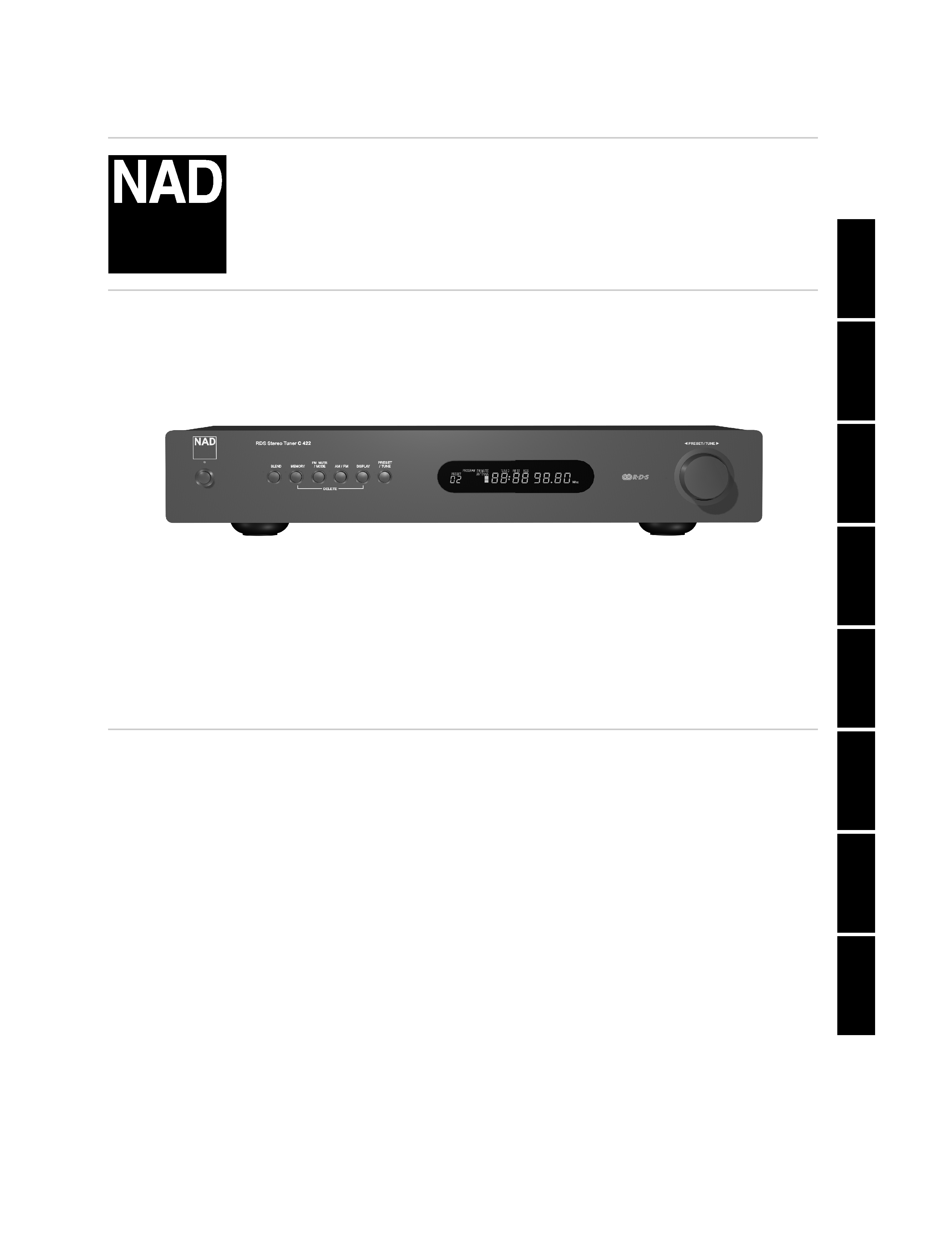
C 422422
Stereo AM/FM Tuner
ENGLISH
FRANÇAIS
DEUTSCH
NEDERLANDS
ESP
AÑOL
IT
ALIANO
POR
TUGUÊS
SVENSKA
Owner's Manual
Manuel d'Installation
Bedienungsanleitung
Gebruikershandleiding
Manual del Usuario
Manuale delle Istruzioni
Manual do Proprietário
Bruksanvisning
®
C422 manual - 6
8/8/03
5:32 PM
Page 1
ENGLISH
FRANÇAIS
DEUTSCH
NEDERLANDS
ESP
AÑOL
IT
ALIANO
POR
TUGUÊS
SVENSKA
2
EXPLANATION OF GRAPHICAL SYMBOLS
The lightning flash with arrowhead symbol, within an
equilateral triangle, is intended to alert the user to the
presence of uninsulated "dangerous voltage" within the
product's enclosure that may be of sufficient magnitude to
constitute a risk of electric shock to persons.
The exclamation point within an equilateral triangle is
intended to alert the user to the presence of important
operating and maintenance (servicing) instructions in the
literature accompanying the appliance.
PRECAUTIONS
Read the Operating Instructions carefully and completely before
operating the unit. Be sure to keep the Operating Instructions for future
reference. All warnings and cautions in the Operating Instructions and on
the unit should be strictly followed, as well as the safety suggestions
below.
INSTALLATION
1Water and Moisture - Do not use this unit near water, such as near a
bathtub, washbowl, swimming pool, or the like.
2 Heat - Do not use this unit near sources of heat, including heating
vents, stoves, or other appliances that generate heat. It also should not
be placed in temperatures less than 5°C (41°F) or greater then 35°C
(95°F).
3 Mounting surface - Place the unit on a flat, even surface.
4Ventilation - The unit should be situated with adequate space around
it so that proper ventilation is assured. allow 10 cm (4 in.) clearance
from the rear and the top of the unit, and 5 cm (2 in.) from each side.
- Do not place on a bed, rug, or similar surface that may block the
ventilation openings. - Do not install the unit in a bookcase cabinet, or
airtight rack where ventilation may be impeded.
5 Objects and liquid entry - Take care that objects or liquids do not get
inside the unit through the ventilation openings.
6 Carts and stands - When placed or mounted on a stand
or cart, the unit should be moved with care. Quick stops,
excessive force, and uneven surfaces may cause the unit
and cart to overturn or fall.
7 Condensation - Moisture may form on the CD pickup lens
when:
· The unit is moved from a cold spot to a warm spot.
· The heating system has just been turned on.
· The unit is used in a very humid room.
· The unit is cooled by an air conditioner.
When this unit has condensation inside, it may not function normally.
Should this occur, leave the unit for a few hours, then try to operate
again.
8Wall or ceiling mounting - The unit should not be mounted on a wall
or ceiling, unless specified in the Operating Instructions.
WARNING! TO REDUCE THE RISK OF FIRE OR
ELECTRONIC SHOCK, DO NOT EXPOSE THIS APPLIANCE
TO RAIN OR MOISTURE
This product is manufactured to comply with the radio
interference requirements of EEC DIRECTIVE 89/68/EEC and
73/23/EEC
ELECTRIC POWER
1 Power Sources - Connect this unit only to power sources specified in
the Operating Instructions, and as marked on the unit.
2 Polarization - As a safety feature, some units are equipped with
polarized AC power plugs which can only be inserted one way into a
power outlet. If it is difficult or impossible to insert the AC power plug
into an outlet, turn the plug over and try again. If it still does not easily
insert into the outlet, please call a qualified service technician to service
or replace the outlet. To avoid defeating the safety feature of the
polarized plug, do not force it into a power outlet.
3 AC power cord - When disconnecting the AC power cord, pull it out
by the AC power plug. Do not pull the cord itself.
· Never handle the AC power plug with wet hands, as this could result
in fire or shock.
· Power cords should be routed to avoid being severely bent, pinched,
or walked upon. Pay particular attention to the cord from the unit to
the power socket.
·Avoid overloading AC outlets and extension cords beyond their
capacity, as this could result in fire or shock.
4 Extension cord - To help prevent electric shock, do not use a polarized
AC power plug with an extension cord, receptacle, or other outlet
unless the polarized plug can be completely inserted to prevent
exposure of the blades of the plug.
5When not in use - Unplug the AC power cord from the AC outlet if
the unit will not be used for several months or more. When the cord is
plugged in, a small amount of current continues to flow to the unit,
even when the power is turned off.
CAUTION
Modifications or adjustments to this product, which are not expressly
approved by the manufacturer, may void the user's right or authority to
operate this product.
MAINTENANCE
Clean the unit only as recommended in the Operating Instructions.
DAMAGE REQUIRING SERVICE
Have the unit serviced by a qualified service technician if
·
The AC power plug has been damaged.
·
Foreign objects or liquid have gotten inside the unit.
·
The unit has been exposed to rain or water - The unit does not
seem to operate normally.
·
The unit exhibits a marked change in performance.
·
The unit has been dropped, or the cabinet has been damaged
DO NOT ATTEMPT TO SERVICE THE UNIT YOURSELF
C422 manual - 6
8/8/03
5:32 PM
Page 2
ENGLISH
FRANÇAIS
DEUTSCH
NEDERLANDS
ESP
AÑOL
IT
ALIANO
POR
TUGUÊS
SVENSKA
3
ANTENNA INFORMATION
If an indoor antenna is used (either built into the set or installed
separately), never allow any part of the antenna to touch the metal parts
of other electrical appliances such as a lamp, TV set etc.
CAUTION POWER LINES
Any outdoor antenna must be located away from all power lines.
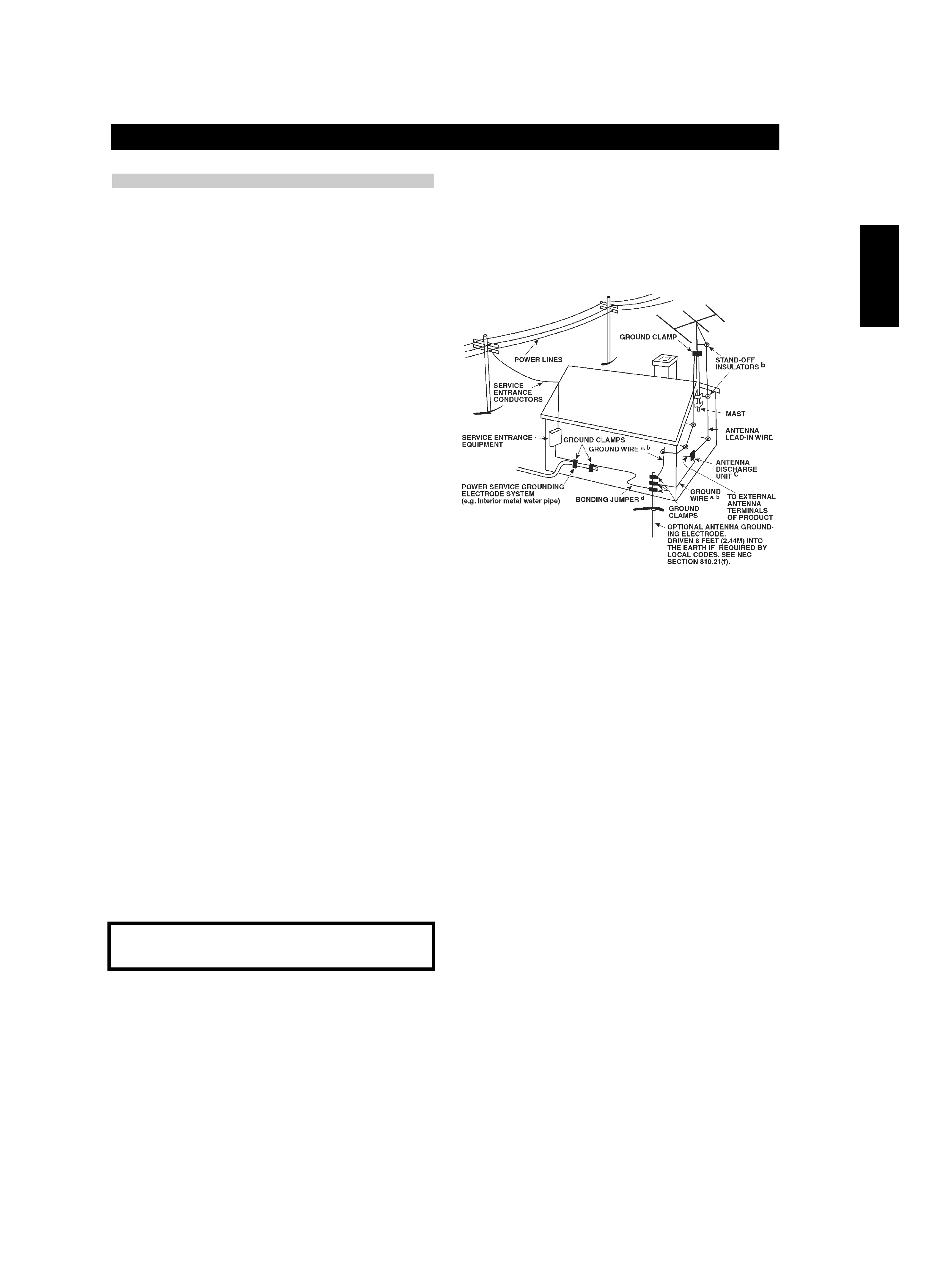
OUTDOOR ANTENNA GROUNDING
If an outside antenna is connected to your tuner or tunerpreamplifier, be
sure the antenna system is grounded so as to provide some protection
against voltage surges and built-up static charges. Article 810 of the
National Electrical Code, ANSI/NFPA No. 70-1984, provides information
with respect to proper grounding of the mast and supporting structure,
grounding of the lead-in wire to an antenna discharge unit, size of
grounding conductors, location of antenna discharge unit, connection to
grounding electrodes and requirements for the grounding electrode.
a. Use No. 10 AWG (5.3mm2) copper, No. 8 AWG (8.4mm2) aluminium,
No. 17 AWG (1.0mm2) copper-clad steel or bronze wire, or larger, as a
ground wire.
b. Secure antenna lead-in and ground wires to house with stand-off
insulators spaced from 4-6 feet (1.22 - 1.83 m) apart.
c. Mount antenna discharge unit as close as possible to where leadin
enters house.
d. Use jumper wire not smaller than No.6 AWG (13.3mm2) copper, or
the equivalent, when a separate antenna-grounding electrode is used.
see NEC Section 810-21 (j).
EXAMPLE OF ANTENNA GROUNDING AS PER NATIONAL ELECTRICAL
CODE INSTRUCTIONS CONTAINED IN ARTICLE 810 - RADIO AND
TELEVISION EQUIPMENT.
NOTE TO CATV SYSTEM INSTALLER: This reminder is provided to call
the CATV system installer's attention to Article 820-40 of the National
Electrica
l Code that provides guidelines for proper grounding and,
in particular, specifies that the ground cable ground shall be connected
to the grounding system of the building, as close to the point of cable
entry as practical.
OWNER'S RECORD
For your convenience, record the model number and serial number (you
will find them on the rear of your set) in the space provided below. Please
refer to them when you contact your dealer in case of difficulty.
Model No. :
Serial No. :
C422 manual - 6
8/8/03
5:32 PM
Page 3
4
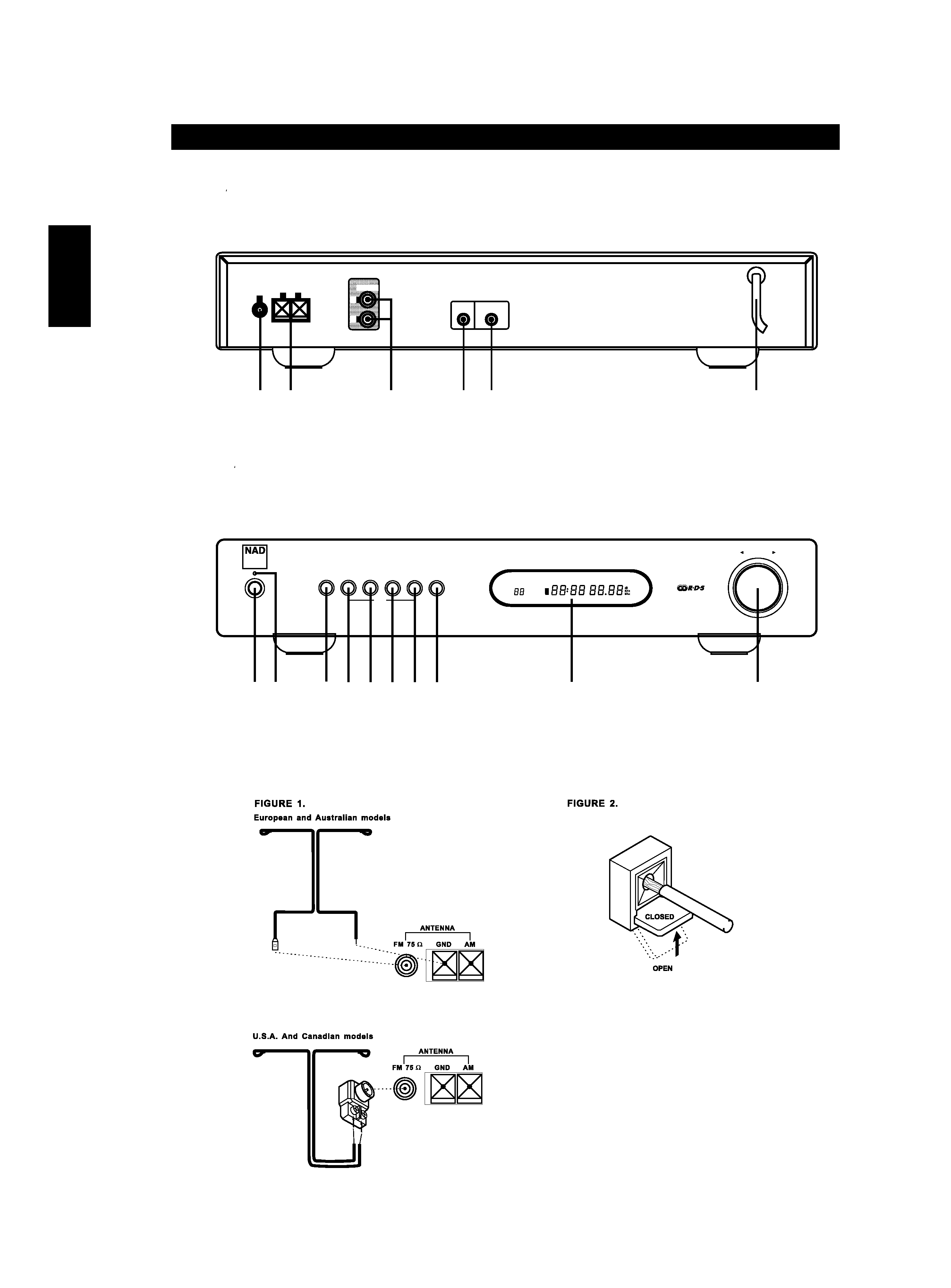
REAR PANEL CONNECTIONS
P
P
FRONT PANEL CONTROLS
P
P
©
2003
NAD
C
422
OUTPUT
ANTENNA
GND
AM
FM
L
R
+12V TRIGGER
IN
IR
IN
6
34
5
1
2
C422 manual - 6
8/8/03
5:32 PM
Page 4
E
N
G
L
IS
H
F
R
A
N
,A
IS
D
E
U
T
S
C
H
N
E
D
E
R
L
A
N
D
S
E
S
P
A
,,O
L
IT
A
L
IA
N
O
P
O
R
T
U
G
U
æ
S
S
V
E
N
S
K
A
PRESET / TUNE
MEMORY
AM / FM
DISPLAY
DELETE
BLEND
FM MUTE
/ MODE
PRESET
/ TUNE
©
20
03
N
A
D
C
42
2
PRESET
PRESET
PROGRAM
PROGRAM FM MUTE
FM MUTE BLEND
BLEND TUNED
TUNED FM ST
FM ST RDS
RDS
ANTENNA
ANTENNA
3
4
5
6
7
1
10
9
8
2
RDS Stereo Tuner C 422

5
ENGLISH
FRANÇAIS
DEUTSCH
NEDERLANDS
ESP
AÑOL
IT
ALIANO
POR
TUGUÊS
SVENSKA
NOTES ON INSTALLATION
Your NAD C 422 should be placed on a firm, level surface. Avoid placing
the unit in direct sunlight, near sources of heat and damp or in poorly
ventilated positions. It comes with RCA leads for connection to your
amplifier. Ensure that leads and connectors are not damaged in any way
and all connectors are firmly pushed home.
If the unit is not going to be used for some time, disconnect the plug
from the AC socket. Should water get into your NAD C 422, shut off the
power to the unit and remove the plug from the AC socket. Have the
unit inspected by a qualified service technician before attempting to use
it again.
DO NOT REMOVE THE COVER; THERE ARE NO USER-
SERVICEABLE PARTS INSIDE.
Use a dry soft cloth to clean the unit. If necessary, lightly dampen the
cloth with soapy water. Do not use solutions containing benzyl or other
volatile agents.
QUICK START
Use the RCA-to-RCA lead to connect the NAD C 422 left & right outputs
to the Tuner Input of your amplifier.
1 Plug in the AC power cord.
2 Connect C 422's output to amplifier.
3 Connect AM and FM antenna.
4 Press the POWER button (No. 1) to turn on the NAD C 422.
5 Press the AM/FM button (No. 6) to select AM or FM reception.
6 Press Preset/Tune button so that "PRESET" isn't lit in display; the
tuner is now in Tune mode.
7 Use TUNE/PRESET
or
to select a station.
REAR PANEL CONNECTIONS
1 FM Antenna - A ribbon wire FM antenna is included and should
be connected to the FM connector at the rear of the unit using the
supplied "balun" adapter (see fig 1). The ribbon aerial should be
mounted on a vertical surface and placed so that it forms a "T".
Experiment with placement of the antenna to find the position that
gives the best signal strength and lowest background noise. An
inadequate FM signal normally results in high levels of hiss, especially
in stereo, and interference from external electrical sources. In areas of
poor FM reception, the tuner section's performance can be improved
by using an externally mounted FM antenna. A qualified aerial
installer will be able to advise and fit a recommended aerial for your
reception conditions.
2 AM Antenna - An AM loop antenna is supplied with the NAD C
422 and is required for AM reception. To connect the AM antenna,
first press the keys on the Antenna terminals downwards. Insert the
bare antenna wires into the two terminal holes and push the
connector keys upwards again to secure the connection (see fig 2).
Test various positions for the antenna but always ensure the loop is
placed vertically for best reception. Placing the antenna close to large
metal items such as metal shelves or radiators may interfere with
reception.
3 Outp
ut - Using twin RCA-to-RCA leads, connect to the left (white)
and right (red) audio outputs to the "Tuner" input or other line-level
input such as "Aux" input of your amplifier. Do not connect this
cable to the amplifier's "Phono" input.
4 IR in - The IR IN connector is used to pass commands from other
units fitted with IR OUT connectors. This allows centralized control of
a complete system, and also allows some of the basic functions of
other NAD components (such as a CD player or cassette-deck) also
equipped with IR IN to be controlled with an NAD system remote
control. To function with such other units, connect the C 422's IR IN
to the IR OUT on the other unit. IR IN connectors can be daisy-
chained, IN to OUT, so that a whole system can be controlled from
the remote control facilities of one unit.
NOTE
The NAD C 422 has a built-in receiver for commands from a remote
control and doesn't need to rely on IR IN to be remotely operated. It
is advisable not to connect IR IN if the other units that have their own
built-in remote control command receiver and are positioned
together, in direct view from the remote control handset. If you are
unsure, try operating the products without IR IN first; if the unit
responds to the remote control command, it will not be necessary to
connect IR IN.
5 12V Trigger in - This input allows the C 422 to be switched
remotely to Stand-by and On by ancillary equipment such as an
amplifier or preamp, AV processor, etc. which are also equipped with
a 12V trigger output. For switching Stand-by/Power On of the C 422
by an external component, connect the12V-trigger input of the C
422 to the remote component's DC output jack. The plug required is
a standard 3.5mm Mini-Jack plug ("mono"): The tip is the live or +
connection, the shaft of the input jack is the 12V-trigger or ground
connection.
NOTE
The C 422's 12V Trigger will work within a range of 6 to 15 V DC
level and typically draws less than 10mA of current. Check the
specifications of the Trigger output terminal on the remote
component to ensure it is compatible with the C 422's 12Vtrigger
input. NAD components equipped with 12V output triggers are fully
compatible with the C 422's 12V input trigger. Before making any
connections to any 12V trigger input or output, make sure all
components are disconnected from the AC mains. Failure to observe
the above may result in damage to the C 422 or any ancillary
components attached to it. If in doubt over the connections,
installation and operation of the 12V trigger output consult your
NAD dealer.
6 AC Line cord - Plug the AC power cord into a live AC wall socket
or to an AC convenience outlet at the rear of your amplifier.
C422 manual - 6
8/8/03
5:32 PM
Page 5