GB
F
D
E
I
S
P
NAD
712
· OWNER'S MANUAL
· MANUEL D'INSTALLATION
· BEDIENUNGSANLEITUNG
· MANUAL DEL USUARIO
· MANUALE DELLE ISTRUZIONI
· BRUKSANVISNING
· MANUAL DO PROPRIETÁRIO
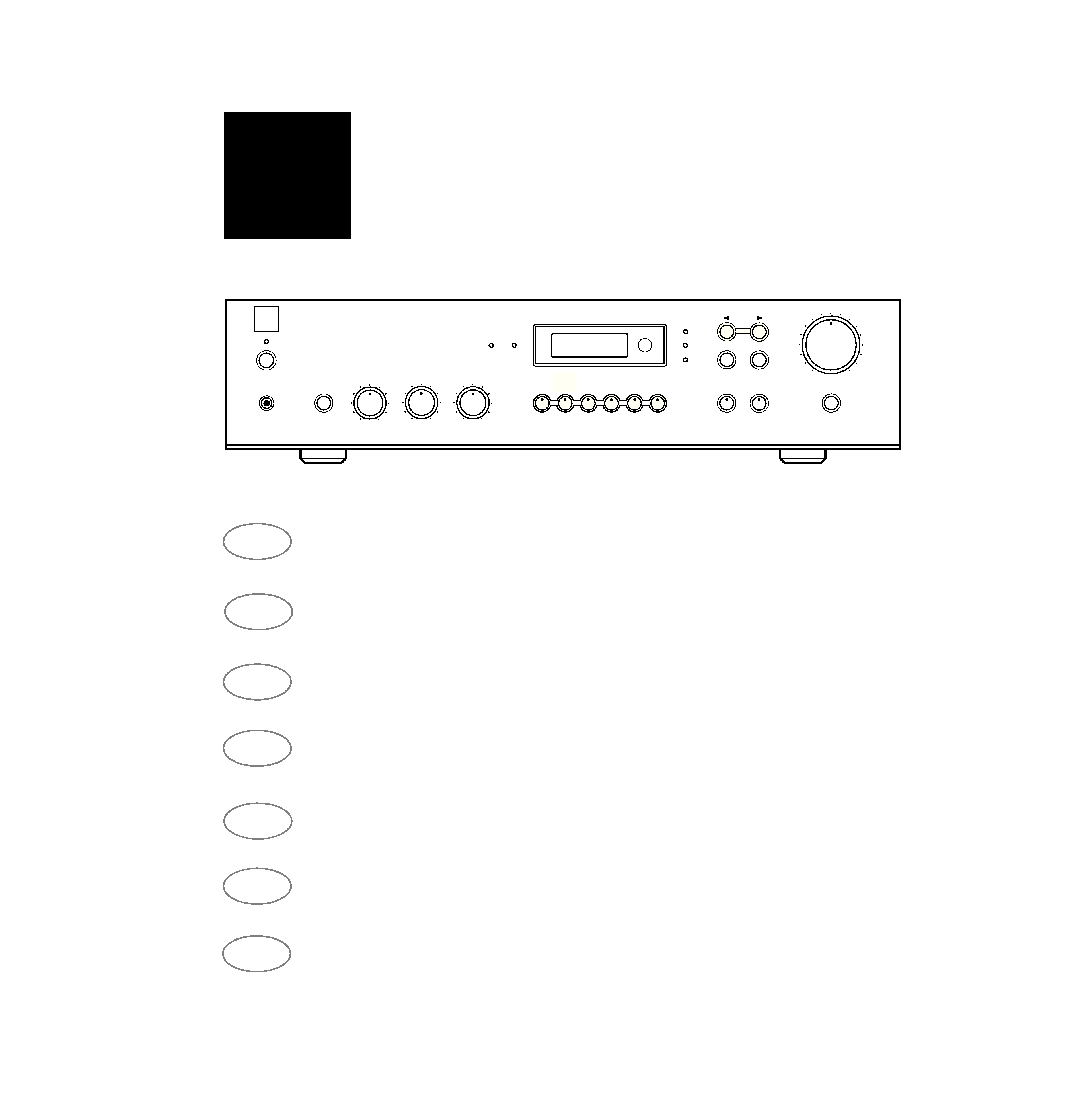
Stereo Receiver 712
NAD
BASS
TREBLE
BALANCE
VOLUME
TAPE 1
MONITOR
TAPE 2
VCR
LD
AUX
CD
PHONES
EXTRA
SPEAKERS
AM
FM
MONO
SEARCH
TUNE
PRESET
FM
STEREO
CENTER
TUNE
MODE
STORE
TUNE
©
1995
NAD
ELECTRONICS
LTD.
712
VIDEO
The graphic symbol of a lightning flash with arrowhead symbol within an
equilateral triangle is intended to alert the user to the presence of
uninsulated "dangerous voltage" within the product's enclosure that
may be of sufficient magnitude to constitute a risk of electric shock
to persons.
The exclamation point within an equilateral triangle is intended to alert
the user to the presence of important operating and maintenance (ser-
vicing) instructions in the literature accompanying the product.
Do not place this unit on an unstable cart, stand or tripod,
bracket or table. The unit may fall, causing serious injury to a
child or adult and serious damage to the unit. Use only with a
cart, stand, tripod, bracket or table recommended by the
manufacturer or sold with the unit. Any mounting of the device
on a wall or ceiling should follow the maufacturer's instructions
and should use a mounting accessory recommended by the
manufacturer.
An appliance and cart combination should be moved with care. Quick stops,
excessive force and uneven surfaces may cause the appliance and cart combi-
nation to overturn.
Read and follow all the safety and operating instructions before connecting or
using this unit. Retain this notice and the owner's manual for future reference.
All warnings on the unit and in it's operating instructions should be adhered to.
Do not use this unit near water; for example, near a bath tub, washbowl, kitchen
sink, laundry tub, in a wet basement or near a swimming pool.
The unit should be installed so that its location or position does not interfere with
its proper ventilation. For example, it should not be situated on a bed, sofa, rug
or similar surface that may block the ventilation openings; or placed in a built-in
installation, such as a bookcase or cabinet, that may impede the flow of air
through its ventilation openings.
The unit should be situated from heat sources such as radiators, heat registers,
stoves or other devices (including amplifiers) that produce heat.
The unit should be connected to a power supply outlet only of the voltage and
frequency marked on its rear panel.
The power supply cord should be routed so that it is not likely to be walked on or
pinched, especially near the plug, convenience receptacles, or where the cord
exits from the unit.
Unplug the unit from the wall outlet before cleaning. Never use benzine, thinner
or other solvents for cleaning. Use only a soft damp cloth.
The power supply cord of the unit should be unplugged from the wall outlet when
it is to be unused for a long period of time.
Care should be taken so that objects do not fall, and liquids are not spilled into
the enclosure through any openings.
This unit should be serviced by qualified service personnel when:
A. The power cord or the plug has been damaged; or
B. Objects have fallen, or liquid has been spilled into the unit; or
C. The unit has been exposed to rain or liquids of any kind; or
D. The unit does not appear to operate normally or exhibits a marked change in
performance; or
E. The device has been dropped or the enclosure damaged.
DO NOT ATTEMPT SERVICING OF THIS UNIT YOURSELF.
REFER SERVICING TO QUALIFIED SERVICE
PERSONNEL.
Upon completion of any servicing or repairs, request the service shop's assur-
ance that only Factory Authorized Replacement Parts with the same
characteristics as the original parts have been used, and that the routine safety
checks have been performed to guarantee that the equipment is in safe operat-
ing condition.
REPLACEMENT WITH UNAUTHORIZED PARTS MAY RESULT IN FIRE,
ELECTRIC SHOCK OR OTHER HAZARDS.
ATTENTION
POUR EVITER LES CHOC ELECTRIQUES, INTRODUIRE LA LAME
LA PLUS LARGE DE LA FICHE DANS LA BORNE CORRESPON-
DANTE DE LA PRISE ET POUSSER JUSQU'AU FOND.
CAUTION
TO PREVENT ELECTRIC SHOCK MATCH WIDE BLADE OF PLUG
TO WIDE SLOT AND FULLY INSERT.
If an indoor antenna is used (either built into the set or installed separately),
never allow any part of the antenna to touch the metal parts of other electrical
appliances such as a lamp, TV set etc.
CAUTION
POWER LINES
Any outdoor antenna must be located away from all power lines.
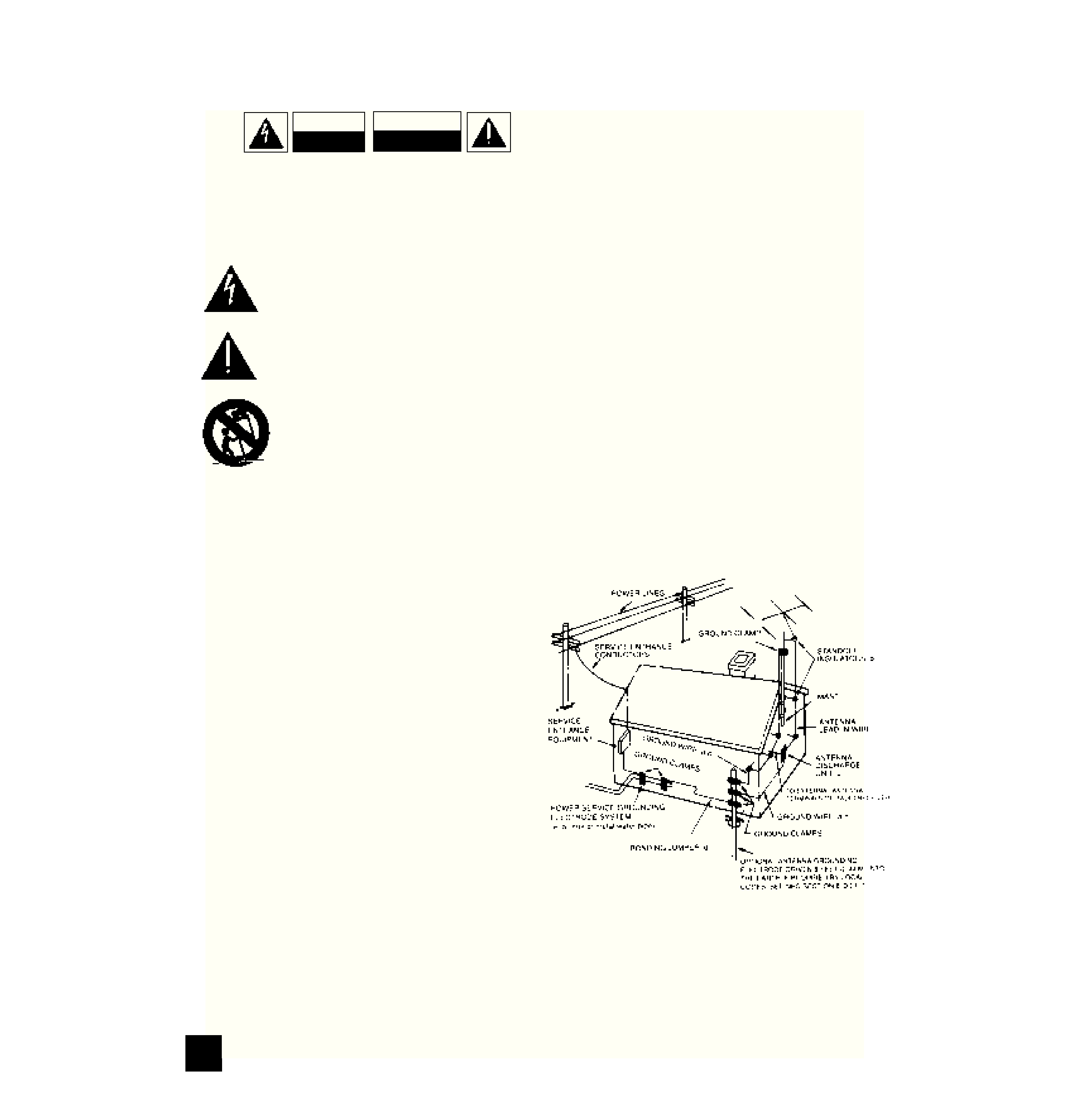
OUTDOOR ANTENNA GROUNDING
If an outside antenna is connected to your tuner or tuner-preamplifier, be sure the
antenna system is grounded so as to provide some protection against voltage
surges and built-up static charges. Section 810 of the National Electrical Code,
ANSI/NFPA No. 70-1984, provides information with respect to proper grounding
of the mast and supporting structure, grounding of the lead-in wire to an antenna
discharge unit, size of grounding conductors, location of antenna discharge unit,
connection to grounding electrodes and requirements for the grounding elec-
trode.
a. Use No. 10 AWG (5.3mm2) copper, No. 8 AWG (8.4mm2) aluminium, No. 17
AWG (1.0mm2) copper-clad steel or bronze wire, or larger, as a ground wire.
b. Secure antenna lead-in and ground wires to house with stand-off insulators
spaced from 4-6 feet (1.22 - 1.83 m) apart.
c. Mount antenna discharge unit as close as possible to where lead-in enters
house.
d. Use jumper wire not smaller than No.6 AWG (13.3mm2) copper, or the equiva-
lent, when a separate antenna-grounding electrode is used. see NEC Section
810-21 (j).
EXAMPLE OF ANTENNA GROUNDING AS PER NATIONAL ELECTRICAL
CODE INSTRUCTIONS CONTAINED IN ARTICLE 810 - RADIO AND TELEVI-
SION EQUIPMENT.
NOTE TO CATV SYSTEM INSTALLER: This reminder is provided to
call the CATV system installer's attention to Article 820-22 of the
National Electrical Code that provides guidelines for proper grounding
and, in particular, specifies that the ground cable ground shall be con-
nected to the grounding system of the building, as close to the point of
cable entry as practical.
CAUTION
RISK OF ELECTRIC
SHOCK DO NOT OPEN
ATTENTION:
RISQUE DE CHOC ELECTRIQUE
NE PAS OUVRIR
CAUTION: TO REDUCE THE RISK OF ELECTRIC SHOCK, DO
NOT REMOVE COVER (OR BACK).
NO USER SERVICEABLE PARTS INSIDE, REFER SERVICING
TO QUALIFIED PERSONNEL.
WARNING: TO REDUCE THE RISK OF FIRE OR ELECTRIC
SHOCK, DO NOT EXPOSE THIS UNIT TO RAIN OR MOISTURE.
IMPORTANT SAFETY INSTRUCTIONS
NAD
2
NAD
3
©
1995
NAD
ELECTRONICS
LTD.
712
©
1995
NAD
ELECTRONICS
LTD.
712
ON
OFF
SOFT
CLIPPING
L
R
+
+
8
L
R
+
+
L
R
L
R
TAPE 1
OUT
TAPE 2
IN
OUT
IN
OUT
PRE
OUT
MAIN
IN
AUX
LD
CD
VIDEO
SOUND
IMPEDANCE
11
15
2
1
12
10
14
13
9
8
37
6
5
4
NAD
LINK
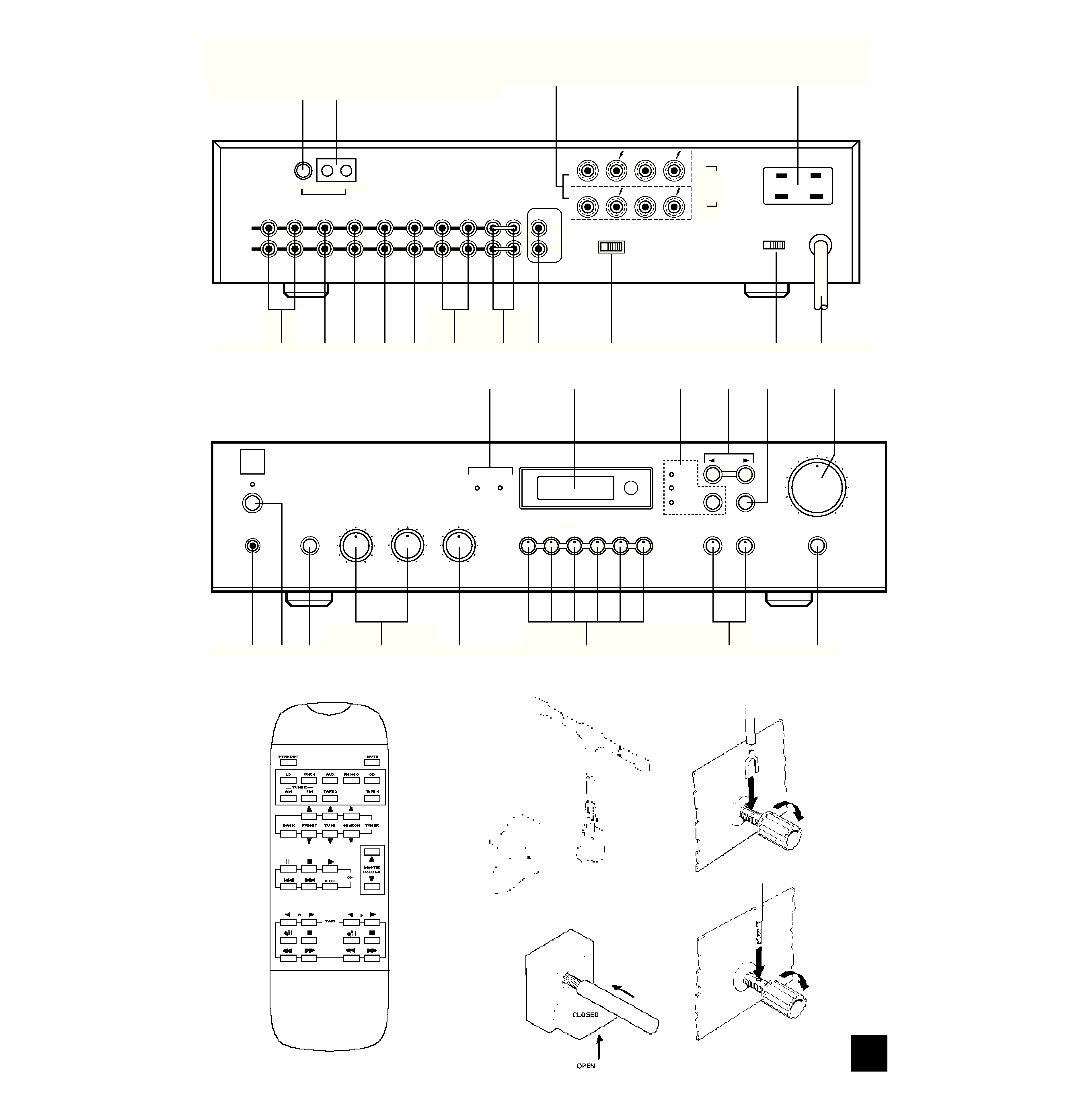
REAR PANEL CONNECTIONS
Stereo Receiver 712
NAD
BASS
TREBLE
BALANCE
VOLUME
TAPE 1
MONITOR
TAPE 2
VCR
LD
AUX
CD
PHONES
EXTRA
SPEAKERS
AM
FM
MONO
SEARCH
TUNE
PRESET
FM
STEREO
CENTER
TUNE
MODE
STORE
TUNE
21
3
4
5
8
11
6
10
9
12
13
7
14
FRONT PANEL CONTROLS
FIGURE 1.
FIGURE 2.
FIGURE 3.
REMOTE CONTROL
FM 75
AM GND
A
B
VIDEO
SPEAKERS

NAD
4
GB
QUICK START
1. Connect the speakers to Speaker A, and any
other sources to the relevant rear sockets.
2. Connect the AM and FM antenna.
3. Plug in the AC power cord.
4. Press the POWER button to turn the NAD-712
on.
5. Press an input selector, AM or FM button.
NOTES ON INSTALLATION
Your NAD-712 should be placed on a firm, level
surface. Avoid placing the unit in direct sunlight or
near sources of heat and damp.
Allow adequate ventilation. Do not place the unit on
a soft surface like a carpet. Do not place it in an
enclosed position such a bookcase or cabinet that
may impede the air-flow through the ventilation slots.
Switch the unit off before making any connections.
The RCA connectors on your NAD-712 are colour
coded for convenience. Red and white are Right and
Left audio, and orange for NAD-Link.
Use high quality leads and connectors for optimum
performance and reliability of connection. Ensure that
leads and connectors are not damaged in any way
and all connectors are firmly pushed home.
For best performance, use quality speaker leads of
16 gauge thickness or more.
If the unit is not going to be used for some time,
disconnect the plug from the AC socket.
Should water get into your NAD-712, shut off the
power to the unit and remove the plug from the AC
socket. Have the unit inspected by a qualified service
technician before attempting to use it again.
Do not remove the cover, there are no user-ser-
viceable parts inside.
Use a dry soft cloth to clean the unit. If necessary,
lightly dampened the cloth with soapy water. Do not
use solutions containing benzol or other volatile
agents.
REAR PANEL CONNECTIONS
1. FM ANTENNA
A ribbon wire FM antenna is included and should
be connected to the FM connector at the rear of the
unit using the `balun' adapter supplied. (see fig. 1)
The ribbon aerial should be mounted on a vertical
surface and placed so that it forms a `T'.
Experiment with placement of the antenna to find
the position that gives the best signal strength and
lowest background noise. An inadequate FM signal
normally results in high levels of hiss, especially in
stereo, and interference from external electrical
sources. In areas of poor FM reception, the tuner sec-
tion's performance can be improved by using an
externally mounted FM antenna. A qualified aerial
installer will be able to advise and fit a recommended
aerial for your reception conditions.
2. AM ANTENNA
An AM wire antenna is supplied with the NAD-712
and is required for AM reception. Open the clip termi-
nal lever and insert the wire from the antenna. (see
fig. 2). Closing the lever will lock the wire in place.
Test various positions for the antenna, but always
ensure the loop is placed vertically for best reception.
Placing the antenna vertically close to large metal
items such as metal shelves or radiators may inter-
fere with reception.
3. TAPE 2 IN/OUT
Connections for analogue recording and playback
to a secondary audio tape recorder of any type. Using
twin phono-to-phono leads, connect to the left and
right `Audio Output' of the tape machine to the TAPE
2 IN connectors for playback. Connect the left and
right `Audio Input' of the tape machine to the TAPE 2
OUT connectors for recording.
4. CD INPUT
Input for CD or other line-level signal source. Use a
twin phono-to-phono lead to connect the CD player
left and right `Audio Outputs' to this input. The NAD-
712 only accepts analogue signals from your CD
player.
5. AUX INPUT
Input for additional line level input signals such as
another CD player. Connect the auxiliary unit's left
and right `Audio Outputs' to this input.
6. LD INPUT
Laser Disc input for the audio signal from a Laser
Disc or other line-level source such as Video-CD,
computer systems or games consoles. Using twin
phono-to-phono leads, connect to the left and right
`Audio Out' of the unit to these inputs.
7. VIDEO SOUND
Input for audio playback from a VCR or other video
device such as a satellite or cable receiver. Using twin
phono-to-phono leads, connect to the left and right
`Audio Out' of the VCR/satellite receiver to these
inputs.
8. TAPE 1 IN/OUT
Connections for analogue recording and playback to
an audio tape recorder of any type. Using twin phono-
to-phono leads, connect to the left and right `Audio
Output' of the tape machine to the TAPE 1 IN connec-
tors for playback and tape monitoring. Connect the left
and right `Audio Input' of the tape machine to the
TAPE 1 OUT connectors for recording.
9. PRE OUT, MAIN IN
Connections to an external pre-amplifier, power
amplifier or processor, such as a surround-sound
decoder. In normal use these should be connected
together using the links supplied. To connect your
NAD-712 to external processor or amplifier sections
first remove these links. Use a twin phono-to-phono
NAD 712 STEREO RECEIVER

NAD
5
GB
lead to connect to the left and right `Audio Input' of the
Power amp or processor to the Pre Out connectors.
Connect the left and right `Audio Output' of the Pre-
amp or processor to the Main In connectors.
Note: The Pre-Out output signal will be affected by
the NAD-712's volume and tone control settings.
10. NAD-LINK IN, OUT
The NAD-Link connector is used to pass com-
mands from the remote control to and from other
units fitted with NAD-Link connectors. This allows
centralised control of a complete system or gives sys-
tem control from more than one room. To function
with other units, connect the NAD-712's NAD-Link
OUT to the NAD-Link IN on the other unit. NAD-Link
connectors can be daisy-chained, IN to OUT, so that
a whole system can be controlled from the remote
control facilities of one unit.
A single NAD-Link connection from a hi-fi system in
a second room will allow remote control of Multi
Room systems.
11. SPEAKERS A AND B
Speaker A terminals are the amplifier outputs for
the speakers located in the main listening room.
Speaker B terminals are the outputs for a second
set of speakers, normally located in another room
such as a dining room or kitchen.
Connect the right speaker to the terminals marked
`R +' and `R' ensuring that the `R+' is connected to
the `+' terminal on your loudspeaker and the `R' is
connected to the loudspeaker's `' terminal.
Connect the terminals marked `L+' and `L' to the
left speaker in the same way.
Always use heavy duty (16 gauge or thicker) strand-
ed wire to connect loudspeakers to your NAD-712.
The high-current binding post terminals can be
used as a screw terminal for cables terminating in
spade or pin connectors or for cables with bare wire
ends (See fig. 3).
SPADE CONNECTORS These should be slotted
under the terminal's screw bushing, which is then fully
tightened. Ensure the connector is tightly secured and
there is no danger of bare metal from spade connec-
tors touching the back panel or another connector, as
this may cause damage.
BARE WIRES AND PIN CONNECTORS are wires
and pin connectors and should be inserted into the
hole in the shaft of the terminal. Unscrew the speaker
terminal's plastic bushing until the hole in the screw
shaft is revealed. Insert the pin or bare cable end into
the hole and secure the cable by tightening down the
terminal's bushing.
Avoid any danger of bare metal from the speaker
cables touching the back panel or another connector.
Ensure that there is only 1/2" (1cm) of bare cable or
pin and no loose strands of speaker wire.
12. SOFT CLIPPING
When an amplifier is driven beyond its specified
power output, a hard distorted sound can be heard on
very loud sounds. This is caused by the amplifier cut-
ting off or `hard clipping' the peaks of sound that it
was not designed to reproduce. The NAD Soft
Clipping circuit gently limits the output of the system
to minimize audible distortion if the amplifier is over-
driven.
If your listening involves moderate power levels you
may leave the Soft Clipping switch to Off. If you are
likely to play at high levels, that could stretch the
amplifier's power capability, then switch Soft Clipping
On.
13. IMPEDANCE SWITCH
Set the Impedance Switch to 4
when the receiver
is being used with two pairs of speakers (Speakers A
& B), or a single pair of speakers with a rated
impedance of 6
or less.
Set the Impedance Switch to 8
when the receiver
is being used with a single pair of speakers, which
have a rated impedance of more than 6 .
14. AC POWER CORD
After you have completed all connections to the
amplifier, plug the AC line cord into a "live" wall sock-
et or into a heavy-duty extension cord.
15. AC OUTLETS (ONLY IN 120V MODEL)
The AC power line cords of other stereo compo-
nents may be plugged into these accessory outlets.
The SWITCHED outlet is intended for all-electronic
products (e.g. an equalizer or other signal processor),
and will be switched on and off by the 712's main
Power button.
The UNSWITCHED outlet should be used to pro-
vide power to products whose operation is
mechanical (e.g. a turntable, CD player, tape deck, or
VCR); such products should be switched on and off
with their own power switches. The UNSWITCHED
outlet can also be used to power a device containing
a clock timer, such as a VCR, or a digital tuner that
requires uninterrupted AC power to maintain station
tuning information stored in its memory.
FRONT PANEL CONTROLS
POWER, SPEAKERS AND HEADPHONE
FUNCTIONS.
1. POWER
Pressing the POWER switch turns the unit On and
the display and volume control LED will illuminate.
Pressing the POWER switch again will turn the
receiver Off.
The NAD-712 uses non-volatile memory to store
preset station information for the tuner, so that these
are not lost when the unit is switched off.
When the NAD-712 is switched On, pressing the
Standby button on the remote handset will put the
NAD-712 into Standby mode. The green Standby
indicator shows that power is being supplied to
the NAD-712, but the system is currently in the
Standby Mode.