SA1521Z
2-WAY ACTIVE
LOUDSPEAKER SYSTEM
USER'S MANUAL
2
3
1. Read these instructions.
2. Keep these instructions.
3. Heed all warnings.
4. Follow all instructions.
5. Do not use this apparatus near water.
6. Clean only with dry cloth.
7. Do not block any ventilation openings. Install in accordance with the
manufacturer's instructions.
8. Do not install near any heat sources such as radiators, heat registers,
stoves, or other apparatus (including amplifiers) that produce heat.
9. Do not defeat the safety purpose of the polarized or grounding-type
plug. A polarized plug has two blades with one wider than the other.
A grounding-type plug has two blades and a third grounding prong.
The wide blade or the third prong are provided for your safety. If the
provided plug does not fit into your outlet, consult an electrician for
replacement of the obsolete outlet.
10.Protect the power cord from being walked on or pinched particularly at
plugs, convenience receptacles, and the point where they exit from the
apparatus.
11.Only use attachments/accessories specified by the manufacturer.
12.Use only with a cart, stand, tripod, bracket, or table specified by the
manufacturer, or sold with the apparatus. When a cart is used, use
caution when moving the cart/apparatus combination to avoid injury
from tip-over.
13.Unplug this apparatus during lightning storms or when unused for long
periods of time.
14.Refer all servicing to qualified service personnel. Servicing is required
when the apparatus has been damaged in any way, such as power-
supply cord or plug is damaged, liquid has been spilled or objects have
fallen into the apparatus, the apparatus has been exposed to rain or
moisture, does not operate normally, or has been dropped.
15.This apparatus shall not be exposed to dripping or splashing, and no
object filled with liquids, such as vases, shall be placed on the apparatus.
16.This apparatus has been designed with Class-I construction and must
be connected to a mains socket outlet with a protective earthing con-
nection (the third grounding prong).
17.This apparatus has been equipped with an all-pole, rocker-style AC
mains power switch. This switch is located on the rear panel and
should remain readily accessible to the user.
18.This apparatus does not exceed the Class A/Class B (whichever is
applicable) limits for radio noise emissions from digital apparatus as
set out in the radio interference regulations of the Canadian Department
of Communications.
ATTENTION -- Le présent appareil numérique n'émet pas de bruits
radioélectriques dépassant las limites applicables aux appareils numériques de
class A/de class B (selon le cas) prescrites dans le réglement sur le brouillage
radioélectrique édicté par les ministere des communications du Canada.
19.Exposure to extremely high noise levels may cause permanent hearing
loss. Individuals vary considerably in susceptibility to noise-induced
hearing loss, but nearly everyone will lose some hearing if exposed to
sufficiently intense noise for a period of time. The U.S. Government's
Occupational Safety and Health Administration (OSHA) has specified
the permissible noise level exposures shown in the following chart.
According to OSHA, any exposure in excess of these permissible limits
could result in some hearing loss. To ensure against potentially danger-
ous exposure to high sound pressure levels, it is recommended that all
persons exposed to equipment capable of producing high sound pres-
sure levels use hearing protectors while the equipment is in operation.
Ear plugs or protectors in the ear canals or over the ears must be worn
when operating the equipment in order to prevent permanent hearing
loss if exposure is in excess of the limits set forth here.
IMPORTANT SAFETY INSTRUCTIONS
WARNING -- To reduce the risk of fire
or electric shock, do not expose this appara-
tus to rain or moisture.
Duration Per Day
Sound Level dBA,
Typical
In Hours
Slow Response
Example
8
90
Duo in small club
6
92
4
95
Subway Train
3
97
2
100
Very loud classical music
1.5
102
1
105
Tami screaming at Adrian about deadlines
0.5
110
0.25 or less
115
Loudest parts at a rock concert
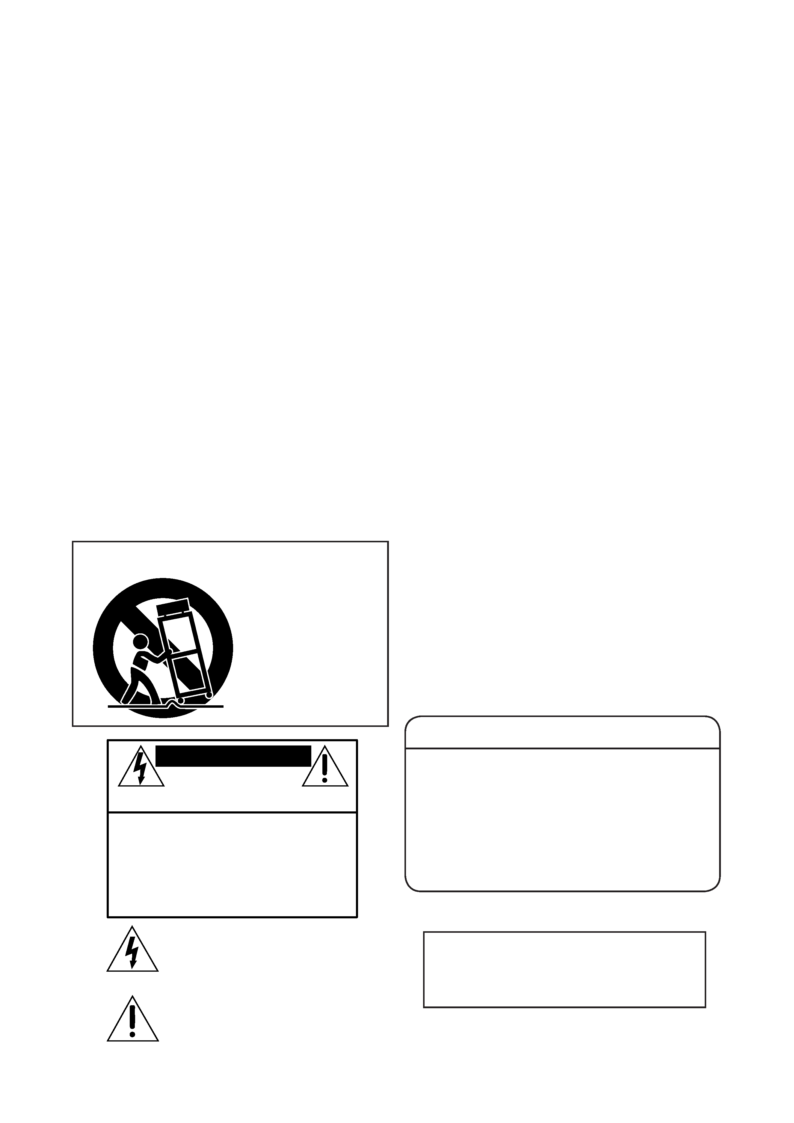
PORTABLE CART WARNING
Carts and stands - The
Component should be used
only with a cart or stand
that is recommended by
the manufacturer.
A Component and cart
combination should be
moved with care. Quick
stops, excessive force, and
uneven surfaces may cause
the Component and cart
combination to overturn.
CAUTION AVIS
RISK OF ELECTRIC
SHOCK
DO NOT OPEN
RISQUE DE CHOC ELECTRIQUE
NE PAS OUVRIR
CAUTION: TO REDUCE THE RISK OF ELECTRIC SHOCK
DO NOT REMOVE COVER (OR BACK)
NO USER-SERVICEABLE PARTS INSIDE
REFER SERVICING TO QUALIFIED PERSONNEL
ATTENTION: POUR EVITER LES RISQUES DE CHOC
ELECTRIQUE, NE PAS ENLEVER LE COUVERCLE. AUCUN
ENTRETIEN DE PIECES INTERIEURES PAR L'USAGER. CONFIER
L'ENTRETIEN AU PERSONNEL QUALIFIE.
AVIS: POUR EVITER LES RISQUES D'INCENDIE OU
D'ELECTROCUTION, N'EXPOSEZ PAS CET ARTICLE
A LA PLUIE OU A L'HUMIDITE
The lightning flash with arrowhead symbol within an equilateral
triangle is intended to alert the user to the presence of uninsulated
"dangerous voltage" within the product's enclosure, that may be
of sufficient magnitude to constitute a risk of electric shock to persons.
Le symbole clair avec point de fl che l'int rieur d'un triangle
quilat ral est utilis pour alerter l'utilisateur de la pr sence
l'int rieur du coffret de "voltage dangereux" non isol d'ampleur
suffisante pour constituer un risque d' l ctrocution.
The exclamation point within an equilateral triangle is intended to
alert the user of the presence of important operating and maintenance
(servicing) instructions in the literature accompanying the appliance.
Le point d'exclamation l'int rieur d'un triangle quilat ral est
employ pour alerter les utilisateurs de la pr sence d'instructions
importantes pour le fonctionnement et l'entretien (service) dans le
livret d'instruction accompagnant l'appareil.

2
3
CONTENTS
IMPORTANT SAFETY INSTRUCTIONS .................................................................................................2
INTRODUCTION ........................................................................................................................................3
REAR PANEL DESCRIPTION ....................................................................................................................4
HOOKUP DIAGRAM ..................................................................................................................................5
CONNECTIONS ..........................................................................................................................................5
PLACEMENT ................................................................................................................................................5
Room Acoustics .................................................................................................................................................................. 6
THERMAL CONSIDERATIONS ............................................................................................................... 6
AC POWER .................................................................................................................................................. 6
SERVICE INFORMATION ..........................................................................................................................7
Warranty Service ................................................................................................................................................................7
Troubleshooting .................................................................................................................................................................7
Repair .................................................................................................................................................................................... 8
CARE AND MAINTENANCE .................................................................................................................... 8
SA1521z SPECIFICATIONS ........................................................................................................................ 9
SA1521z LIMITED WARRANTY ...............................................................................................................11
Don't forget to visit our website at www.mackie.com
for more information about this and other Mackie products.
INTRODUCTION
mammoth aluminum heatsink that eliminates the need
for fans. A tremendous benefit of having the ampli-
fiers located within the loudspeaker cabinet is that the
SA1521z functions as a system, optimizing acoustic,
electronic, and mechanical designs to achieve the high-
est level of performance and value.
The rear mounted amplifier assembly features
separate signal and AC power panels separated by the
heatsink. The signal input panel contains:
· an input XLR and loop-through XLR
· a volume level control
· Power ON indicator
· Signal Present indicator
· Limit indicator
· Thermal Protection indicator
The cabinet is constructed using both 18 mm Baltic
birch plywood and pressure injected structural resin.
A carrying handle is integrated into each side for easy
loading and transport.
Thank you for choosing Mackie's active sound reinforce-
ment loudspeaker systems.
The SA1521z is a high-efficiency, high output, horn-
loaded, 2-way, wide-dispersion, active sound reinforce-
ment system. The SA1521z benefits from the integration
of 500 watts of amplifier power, complete active control
electronics, and precision transducer components.
These elements together form a speaker system with
unprecedented output, resolution, and clarity.
The 1.75-inch neodymium high-frequency compres-
sion driver features a low-distortion optimized symmet-
ric phase plug.
The low frequencies are produced by a high-output
15-inch woofer featuring a 3-inch high-temperature
voice coil.
Connecting and setting up the SA1521z is a breeze. It
accepts a line-level signal via a female XLR input jack.
A male XLR Thru jack is provided for daisy-chaining the
signal to additional SA1521z cabinets.
Two built-in power amplifiers provide 100 watts rms
for the high-frequency driver and 400 watts rms for the
low-frequency driver. The amplifier modules sit on a
Part No. 0013860 Rev. A 12/04
©2004 LOUD Technologies Inc. All Rights Reserved. Printed in China.
4
5
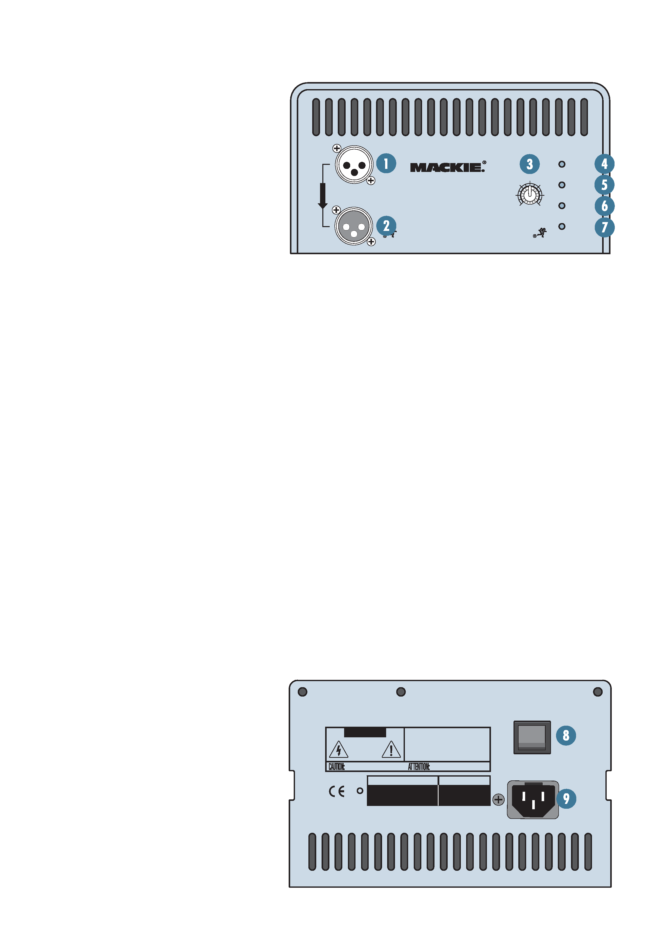
REAR PANEL DESCRIPTION
1. MAIN INPUT
This is a female XLR-type connector that
accepts a balanced line-level signal from a
mixing console or other signal source.
2. LOOP OUT
This is a male XLR-type connector that
produces exactly the same signal that is
connected to the MAIN INPUT jack. Use it to
daisy-chain several SA1521z's together off the
same signal source.
3. Level Control
This controls the overall signal level at the input to
the built-in power amplifiers. It ranges from 15 dB to
+5 dB of gain. The center detent is 0 dB (unity gain).
4. Power ON Indicator
When the POWER switch is turned on, and the
linecord is connected to an active AC power supply, this
indicator lights green to let you know that you're ready
to rock and roll. The cool blue LED on the front of the
cabinet works in the same way.
5. SIGNAL Present Indicator
This LED illuminates whenever there is a signal pres-
ent at the MAIN INPUT connector on the rear panel.
It senses the signal just after the level control, so if
the level control is turned down, the SIGNAL Present
indicator turns off.
6. LIMIT Indicator
The SA1521z has a built-in limiter that prevents the
amplifier outputs from clipping or overdriving
the transducers. The LIMIT indicator lights
when the limiter is activated. It's okay for the
LIMIT indicator to blink occasionally, but if it
blinks frequently or lights continuously, turn
down the level control until the LIMIT indica-
tor only blinks occasionally.
7. THERMAL Indicator
There is also a thermal protection circuit that mon-
itors the internal temperature of the amplifiers and
heatsink. If the temperature should exceed a safe oper-
ating level, this indicator lights and the signal is muted to
allow the amplifiers to cool. When the temperature cools
to a safe level once again, the thermal protection circuit
deactivates and normal operation continues.
Note: Activation of the thermal protection circuit is
an indication that you should take steps to avoid con-
tinued thermal problems. See "Thermal Considerations"
on page 6.
8. POWER Switch
Use this switch to turn the SA1521z on and off. Make
sure the level control is turned down before you turn it
on.
9. AC Receptacle
This is where you connect the AC linecord to provide
AC power to the SA1521z's built-in power amplifiers.
Plug the linecord into an AC socket properly configured
for your particular model.
SA1521Z
ACTIVE SOUND REINFORCEMENT
SPEAKER SYSTEM
4
5
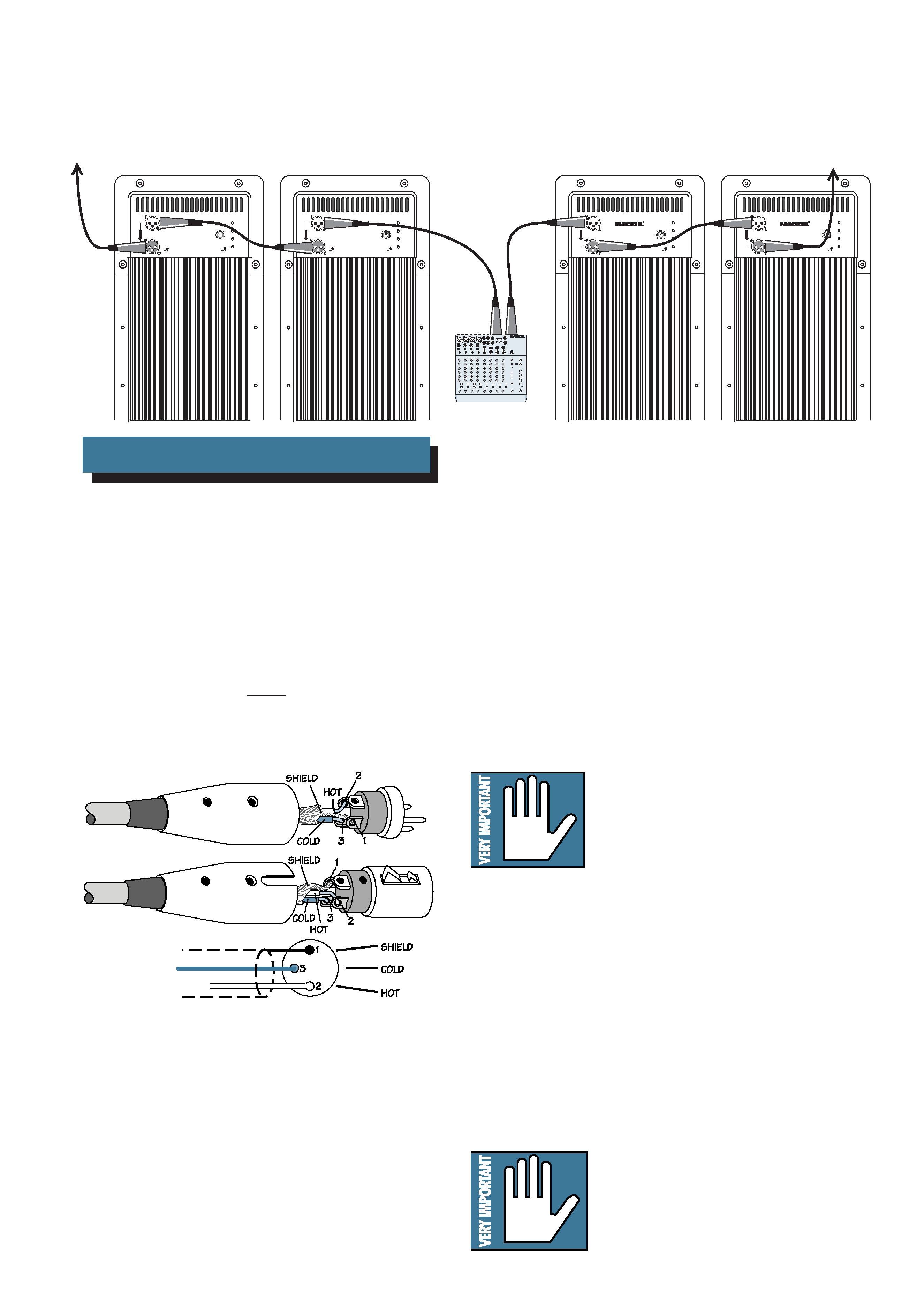
HOOKUP DIAGRAM
Balanced XLR Connectors
There is also a male XLR connector labeled LOOP
OUT. This is also wired according to the above AES
standard.
The LOOP OUT connector allows you to connect
more than one SA1521z to your system. Simply plug the
signal source (i.e., mixer output) into the first MAIN
INPUT jack, and patch that speaker's LOOP OUT jack
to the next MAIN INPUT jack, and so on, daisy-chaining
multiple speakers.
CONNECTIONS
DAISY-CHAINING MULTIPLE SA1521z'S
The SA1521z has one female XLR input that accepts
a balanced line-level signal. When connecting a balanced
signal, be sure it's wired per AES (Audio Engineering
Society) standards:
XLR
Hot (+)
Pin 2
Cold ()
Pin 3
Shield (Ground) Pin 1
The LOOP OUT jack is wired straight from the MAIN
INPUT connector -- there is no electronic circuitry
between -- so the signal coming out of the LOOP OUT
jack is exactly the same as the signal going in.
PLACEMENT
The SA1521z speaker is designed to sit on the floor or
stage. It can be pole-mounted via the built-in socket on
the bottom of the cabinet. Be sure the pole is capable of
supporting the weight of the SA1521z.
WARNING: The cabinet has no rig-
ging points and is not suitable for
rigging.
NEVER attempt to suspend
the SA1521z by its handles.
You can create a horizontal array by placing the cabinets
side-by-side. However, you should have a good understand-
ing of the relationship between the splay angle (the angle
between the facing sides of the cabinets), the on-axis
power, and frequency cancellation effects between cabinets.
When two cabinets are placed side-by-side, the actual
splay angle is 20º (determined by a 10º angle on each
cabinet side). As the splay angle increases toward the
angle of horizontal coverage (90º for the SA1521z), the
on-axis power decreases, but the frequency response be-
comes smoother as the comb-filtering effects (caused by
the interaction in the area of double-coverage) decrease.
As with any powered components,
protect them from moisture. If you
are setting them up outdoors, make
sure they are under cover if you
expect rain.
SA1521Z
ACTIVE SOUND REINFORCEMENT
SPEAKER SYSTEM
SA1521Z
ACTIVE SOUND REINFORCEMENT
SPEAKER SYSTEM
SA1521Z
ACTIVE SOUND REINFORCEMENT
SPEAKER SYSTEM
SA1521Z
ACTIVE SOUND REINFORCEMENT
SPEAKER SYSTEM
Mixer or
Preamplifier
Right
Line level
Output
Left
Line level
Output
To Next
Speaker
To Next
Speaker
1202-VLZPRO