SA1521
2-WAY ACTIVE
SPEAKER SYSTEM
USER'S MANUAL
2
PORTABLE CART WARNING
Carts and stands - The
Component should be used
only with a cart or stand
that is recommended by
the manufacturer.
A Component and cart
combination should be
moved with care. Quick
stops, excessive force, and
uneven surfaces may cause
the Component and cart
combination to overturn.
SAFETY INSTRUCTIONS
1. Read Instructions -- All the safety and operation instructions
should be read before this Mackie product is operated.
2. Retain Instructions -- The safety and operating instructions
should be kept for future reference.
3. Heed Warnings -- All warnings on this Mackie product and in
these operating instructions should be followed.
4. Follow Instructions -- All operating and other instructions
should be followed.
5. Water and Moisture -- This Mackie product should not be used
near water for example, near a bathtub, washbowl, kitchen sink,
laundry tub, in a wet basement, near a swimming pool, swamp, or
salivating St. Bernard dog, etc.
6. Cleaning -- Clean only with a dry cloth.
7. Ventilation -- This Mackie product should be situated so that its
location or position does not interfere with its proper ventilation. For
example, the Component should not be situated on a bed, sofa,
rug, or similar surface that may block any ventilation openings, or
placed in a built-in installation such as a bookcase or cabinet that
may impede the flow of air through ventilation openings.
8. Heat -- This Mackie product should be situated away from heat
sources such as radiators or other devices which produce heat.
WARNING: The heatsink may reach high temperatures during
standard use. To ensure proper operation, allow a minimum of 6
inches of clearance from the heatsink surface and adequate
ventilation.
9. Power Sources -- This Mackie product should be connected to a
power supply only of the type described in these operation
instructions or as marked on this Mackie product.
10. Power Cord Protection -- Power supply cords should be routed
so that they are not likely to be walked upon or pinched by items
placed upon or against them, paying particular attention to cords at
plugs, convenience receptacles, and the point where they exit this
Mackie product.
11. Object and Liquid Entry -- Care should be taken so that objects
do not fall into and liquids are not spilled into this Mackie product.
12. Damage Requiring Service -- This Mackie product should be
serviced only by qualified service personnel when:
A. The power-supply cord or the plug has been
damaged; or
B. Objects have fallen, or liquid has spilled into this
Mackie product; or
C. This Mackie product has been exposed to rain; or
D. This Mackie product does not appear to operate
normally or exhibits a marked change in performance;
or
E. This Mackie product has been dropped, or its chassis
damaged.
13. Servicing -- The user should not attempt to service this Mackie
product beyond those means described in this operating manual. All
other servicing should be referred to the Mackie Service Department.
14. To prevent electric shock, do not use this polarized plug with an
extension cord, receptacle, or other outlet unless the blades can be
fully inserted to prevent blade exposure.
Pour prévenir les chocs électriques ne pas utiliser cette fiche
polariseé avec un prolongateur, un prise de courant ou une autre
sortie de courant, sauf si les lames peuvent être insérées à fond
sans laisser aucune pariie à découvert.
15. Grounding or Polarization -- Precautions should be taken so
that the grounding or polarization means of this Mackie product is
not defeated.
16. Power Precaution -- Unplug this Mackie product during
lightning storms or when unused for long periods of time. Note that
this Mackie product is not completely disconnected from the AC
mains when the power switch is in the OFF position.
17. This apparatus does not exceed the Class A/Class B (whichever
is applicable) limits for radio noise emissions from digital apparatus
as set out in the radio interference regulations of the Canadian
Department of Communications.
ATTENTION --Le présent appareil numérique n'émet pas de
bruits radioélectriques dépassant las limites applicables aux
appareils numériques de class A/de class B (selon le cas) prescrites
dans le règlement sur le brouillage radioélectrique édicté par les
ministere des communications du Canada.
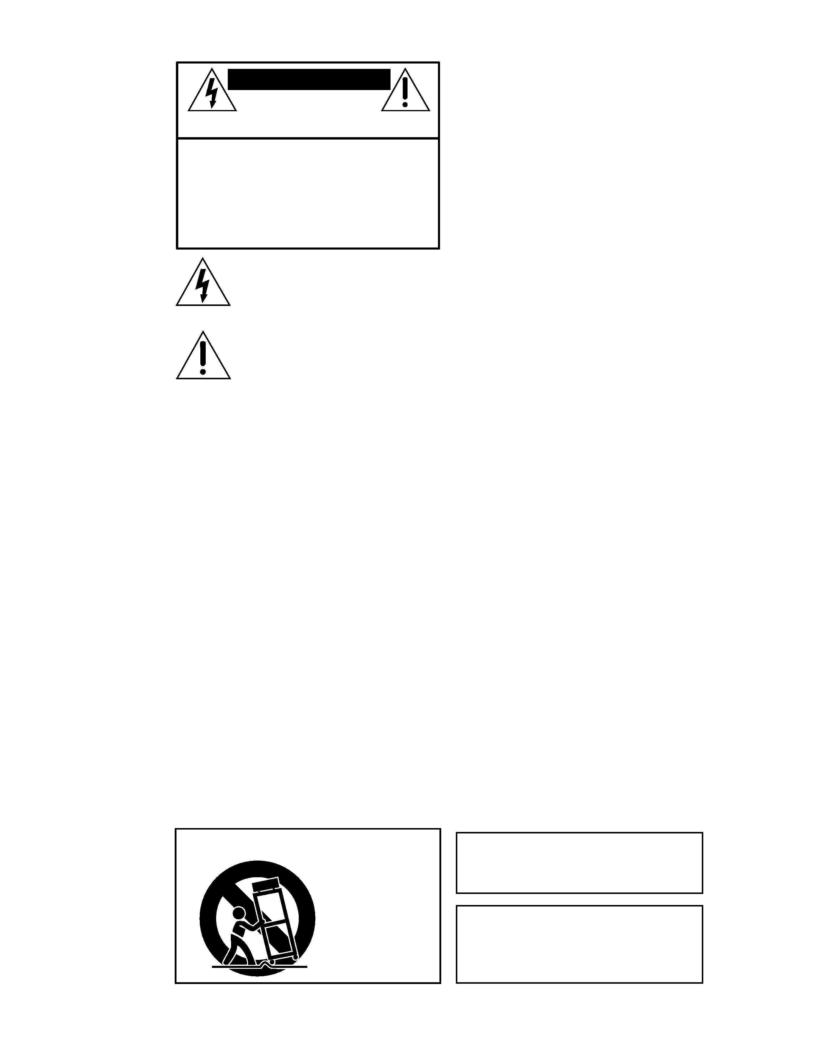
CAUTION
AVIS
RISK OF ELECTRIC
SHOCK
DO NOT OPEN
RISQUE DE CHOC ELECTRIQUE
NE PAS OUVRIR
CAUTION: TO REDUCE THE RISK OF ELECTRIC SHOCK
DO NOT REMOVE COVER (OR BACK)
NO USER-SERVICEABLE PARTS INSIDE
REFER SERVICING TO QUALIFIED PERSONNEL
ATTENTION: POUR EVITER LES RISQUES DE CHOC
ELECTRIQUE, NE PAS ENLEVER LE COUVERCLE. AUCUN
ENTRETIEN DE PIECES INTERIEURES PAR L'USAGER. CONFIER
L'ENTRETIEN AU PERSONNEL QUALIFIE.
AVIS: POUR EVITER LES RISQUES D'INCENDIE OU
D'ELECTROCUTION, N'EXPOSEZ PAS CET ARTICLE
A LA PLUIE OU A L'HUMIDITE
The lightning flash with arrowhead symbol within an equilateral
triangle is intended to alert the user to the presence of uninsulated
"dangerous voltage" within the product's enclosure that may be
of sufficient magnitude to constitute a risk of electric shock to persons.
Le symbole éclair avec point de flèche à l'intérieur d'un triangle
équilatéral est utilisé pour alerter l'utilisateur de la présence à
l'intérieur du coffret de "voltage dangereux" non isolé d'ampleur
suffisante pour constituer un risque d'éléctrocution.
The exclamation point within an equilateral triangle is intended to
alert the user of the presence of important operating and maintenance
(servicing) instructions in the literature accompanying the appliance.
Le point d'exclamation à l'intérieur d'un triangle équilatéral est
employé pour alerter les utilisateurs de la présence d'instructions
importantes pour le fonctionnement et l'entretien (service) dans le
livret d'instruction accompagnant l'appareil.
WARNING -- To reduce the risk of fire or
electric shock, do not expose this appliance to
rain or moisture.
WARNING -- The cabinet has no rigging
points and is not suitable for flying. Never
attempt to suspend the cabinet by its handles.
3
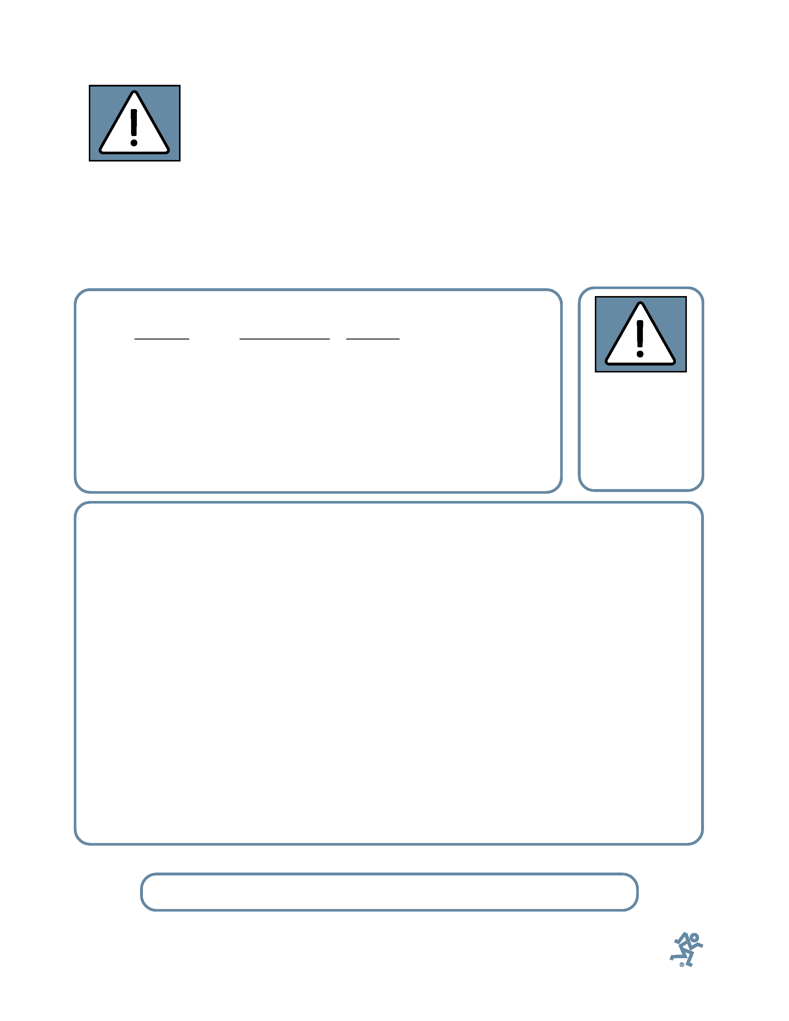
Lend Me Your Ears
Exposure to extremely
high noise levels may cause
permanent hearing loss. In-
dividuals vary considerably
in susceptibility to noise-
induced hearing loss, but nearly everyone
will lose some hearing if exposed to suffi-
ciently intense noise for a period of time.
The U.S. Government's Occupational
Safety and Health Administration (OSHA)
has specified the permissible noise level ex-
posures shown in this chart.
According to OSHA, any exposure in ex-
cess of these permissible limits could result
in some hearing loss. To ensure against po-
tentially dangerous exposure to high
sound-pressure levels, it is recommended
that all persons exposed to equipment ca-
pable of producing these levels use hearing
protectors while this unit is in operation.
Ear plugs or protectors in the ear canals or
over the ears must be worn when operating
this amplification system in order to pre-
vent a permanent hearing loss if exposure is
in excess of the limits set forth here.
Contents
SAFETY INSTRUCTIONS .............................................................................................................2
INTRODUCTION ...........................................................................................................................4
REAR PANEL DESCRIPTION ........................................................................................................4
HOOKUP DIAGRAM .....................................................................................................................5
CONNECTIONS ............................................................................................................................5
PLACEMENT .................................................................................................................................6
AC POWER ...................................................................................................................................6
THERMAL CONSIDERATIONS .....................................................................................................6
SERVICE INFORMATION .............................................................................................................7
Warranty Service ....................................................................................................... 7
Troubleshooting .......................................................................................................... 7
Repair ....................................................................................................................... 8
CARE AND MAINTENANCE .........................................................................................................8
SA1521 SPECIFICATIONS ...........................................................................................................9
Architects and Engineers' Specifications ..................................................................... 10
FREQUENCY RESPONSE GRAPH ..............................................................................................10
SA1521 LIMITED WARRANTY ...................................................................................................11
Don't forget to visit our website at www.mackie.com
for more information about this and other Mackie products.
Duration Per Day
Sound Level dBA, Typical
In Hours
Slow Response
Example
8
90
Duo in small club
692
4
95
Subway Train
397
2
100
Very loud classical music
1.5
102
1
105
Patrice screaming at Ron about deadlines
0.5
110
0.25 or less
115
Loudest parts at a rock concert
The SA1521
can produce a
maximum SPL of
133 dB @ 1m
Part No. 820-262-00 Rev. B 03/02
© 2002 Mackie Designs Inc. All Rights Reserved.
4
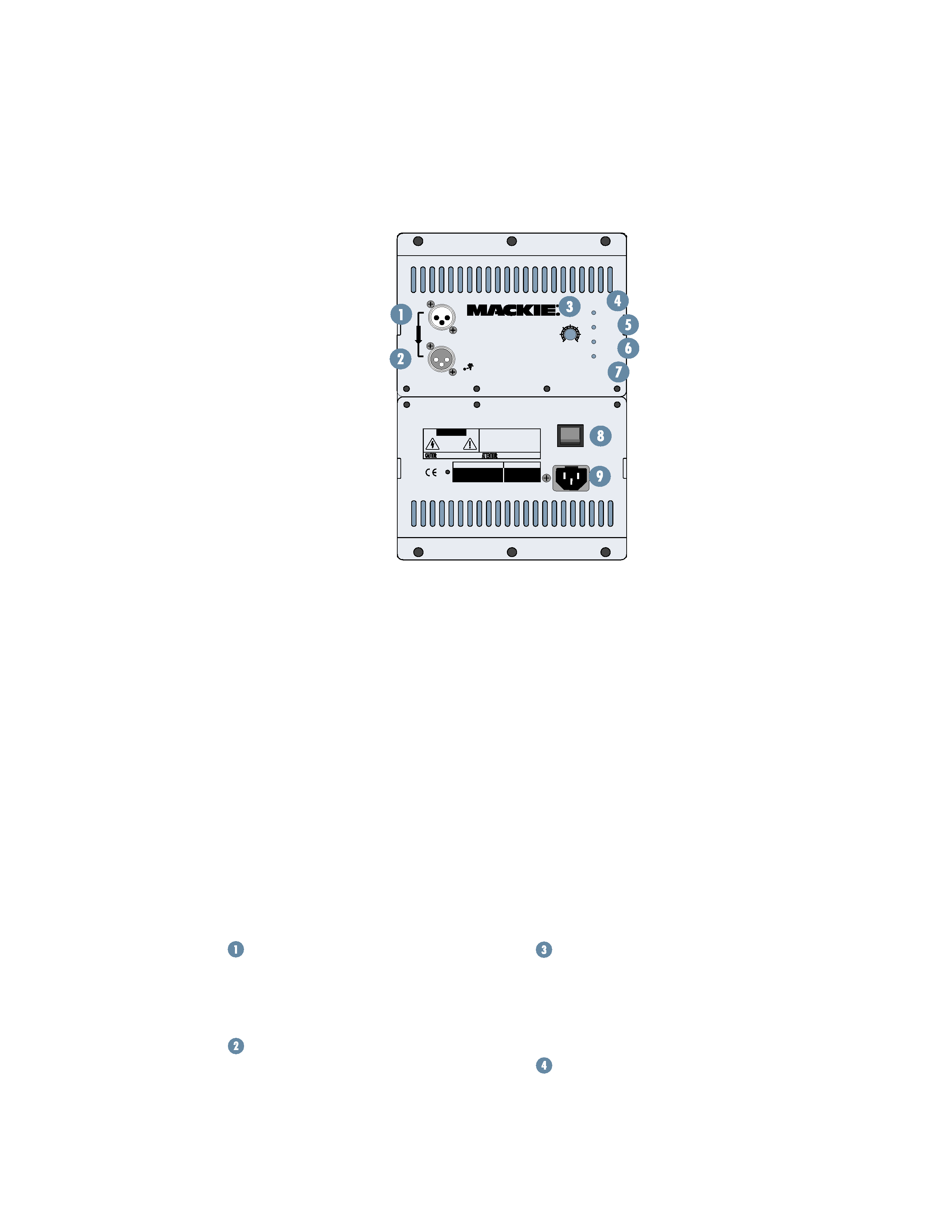
REAR PANEL DESCRIPTION
MAIN INPUT
This is a female XLR-type connector that
accepts a balanced line-level signal from a
mixing console or other signal source.
LOOP OUT
This is a male XLR-type connector that
produces exactly the same signal that is
connected to the
MAIN INPUT jack. Use it
to daisy-chain several SA1521s together off
the same signal source.
INTRODUCTION
100 Hz. It's quite capable of dealing with
the high phase shift characteristics of large
diameter woofers.
More importantly, the amplifier incorpo-
rates the high-voltage output required to
generate extreme SPL levels. The SA1521
also features a low-distortion, high-output
horn design. This was
developed to provide the
correct power response
and phase alignment
characteristics at the
crossover frequency. Ultra-
wide, controlled dispersion
performance continues to
be one of Mackie Designs'
most important engineer-
ing goals for sound
reinforcement enclosures.
With the resulting 75º x
65º dispersion pattern, the
SA1521 provides very
open, natural sound
reproduction at extreme
output levels.
The rear mounted am-
plifier assembly features separate signal and
AC power panels separated by a large alumi-
num heatsink. The signal input panel contains:
· an input XLR and loop through XLR
· a volume level control
· Power On indicator
· Signal Present indicator
· Limit indicator
· Thermal protection indicator
The system accepts a standard line-level
signal via an XLR input connector.
The SA1521 cabinet is constructed using
both multi-layered plywood and pressure-
injected structural resin caps. The top and
bottom sections both have handles for easy
movement and relocation.
Level Control
This controls the overall signal level at the
input to the built-in power amplifiers. This
control ranges from 15 dB to +5 dB of
gain. The center detent is 0 dB (unity gain).
Power ON Indicator
When the power switch is turned on,
and the linecord is connected to an active
AC power supply, this indicator lights green
to let you know that you're ready to rock
WARNING: THIS SURFACE MAY REACH HIGH TEMPERATURE DURING
STANDARD USE. TO ENSURE PROPER OPERATION ALLOW A MINIMUM OF 6 INS.
OF CLEARANCE FROM THIS SURFACE AND ADEQUATE VENTILATION. TO REDUCE
THE RISK OF ELECTRIC SHOCK DO NOT REMOVE THIS PANEL OR ANY ATTACHED
COMPONENT. NO OPERATOR SERVICEABLE PARTS INSIDE. REFER SERVICING TO
QUALIFIED PERSONNEL. TO REDUCE THE RISK OF FIRE OR ELECTRIC SHOCK, DO NOT
EXPOSE THIS APPLIANCE TO RAIN OR MOISTURE.
RISK OF ELECTRIC SHOCK
DO NOT OPEN
REPLACE WITH THE SAME TYPE FUSE AND RATING.
DISCONNECT SUPPLY CORD BEFORE CHANGING FUSE
UTILISE UN FUSIBLE DE RECHANGE DE MÊME TYPE.
DEBRANCHER AVANT DE REMPLACER LE FUSIBLE
CAUTION
AVIS: RISQUE DE CHOC ELECTRIQUE -- NE PAS OUVRIR
SERIAL NUMBER
MANUFACTURING DATE
ON
POWER
THERMAL
SIGNAL
LIMIT
LOOP OUT
MAIN INPUT
PARALLEL
0dB
-15
+5
SA1521
CONCEIVED AND DESIGNED BY MACKIE DESIGNS INC, WOODINVILLE, WA, USA
AND MACKIE EUROPE · MANUFACTURED IN ITALY · COPYRIGHT ©2001 ·
THE FOLLOWING ARE TRADEMARKS OR REGISTERED TRADEMARKS OF MACKIE DESIGNS INC.:
"MACKIE", AND THE "RUNNING MAN" FIGURE · PATENT PENDING
ACTIVE SOUND REINFORCEMENT
SPEAKER SYSTEM
Thank you for choosing Mackie Designs'
active sound reinforcement speaker systems.
The SA1521 is a high-efficiency, extreme
output, active two-way, wide dispersion,
sound reinforcement speaker system. The
SA1521 benefits from the integration of
500 watts of amplifier power, complete ac-
tive control electronics,
and RCF Precision
components. These
elements together
form a speaker system
with 100 dB of sensitiv-
ity (@ 1 watt/1 meter).
The result is unprec-
edented output,
resolution and clarity.
The components
inside the SA1521
incorporate several
state of the art ad-
vancements in
transducer technology.
These advancements
have been in develop-
ment for over two
years. The compression driver is a new
1.75-inch titanium diaphragm design. It
features a 3-slot, low-distortion geometry
phase plug. The amplifier for the compres-
sion driver incorporates a Class AB topology
renowned for its clarity and warmth.
The low-frequency amplifier features an
innovative Class G hybrid topology. By
incorporating a high-frequency switcher
into the amplifier power supply design and
focusing the design effort into generating
the best possible "application-specific"
amplifier design, we arrived at a high-
efficiency amplifier that delivers 400 watts
rms (continuous), and 600 watts peak at
5
and roll. The cool blue LED on the front of
the cabinet works in the same way.
SIGNAL Present Indicator
This LED illuminates whenever there is
a signal present at the
MAIN INPUT connec-
tor on the rear panel. It senses the signal
just after the Level control, so if the Level
control is turned down, the
SIGNAL Present
indicator turns off.
LIMIT Indicator
The SA1521 has a built-in limiter that
prevents the amplifier outputs from clip-
ping or overdriving the transducers. The
LIMIT indicator lights when the limiter is
activated. It's okay for the
LIMIT indicator
to blink occasionally, but if it blinks fre-
quently or lights continuously, turn down
the level control until the
LIMIT indicator
only blinks occasionally.
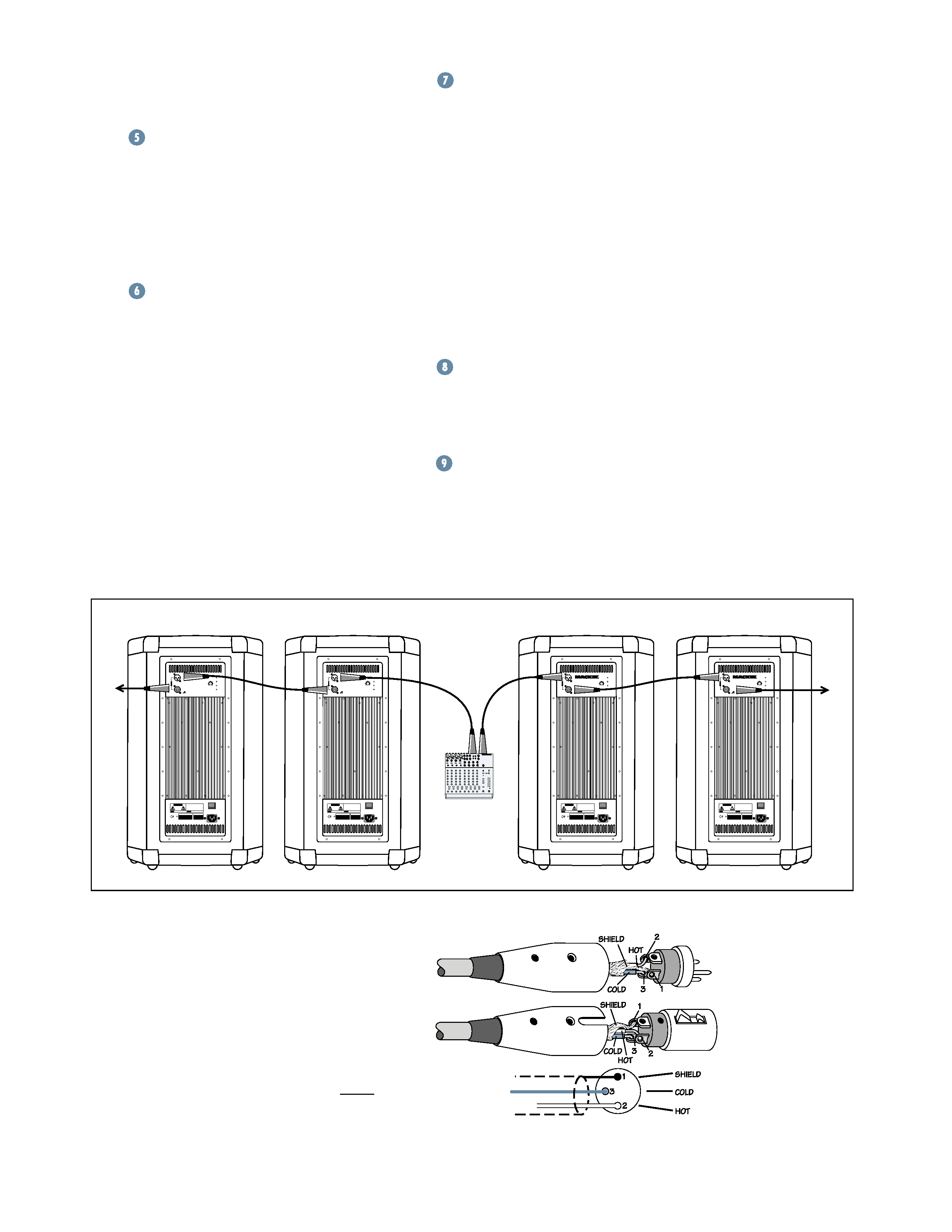
HOOKUP DIAGRAM
1202-VLZ PRO
WARNING: THIS SURFACE MAY REACH HIGH TEMPERATURE DURING
STANDARD USE. TO ENSURE PROPER OPERATION ALLOW A MINIMUM OF 6 INS.
OF CLEARANCE FROM THIS SURFACE AND ADEQUATE VENTILATION. TO REDUCE
THE RISK OF ELECTRIC SHOCK DO NOT REMOVE THIS PANEL OR ANY ATTACHED
COMPONENT. NO OPERATOR SERVICEABLE PARTS INSIDE. REFER SERVICING TO
QUALIFIED PERSONNEL. TO REDUCE THE RISK OF FIRE OR ELECTRIC SHOCK, DO NOT
EXPOSE THIS APPLIANCE TO RAIN OR MOISTURE.
RISK OF ELECTRIC SHOCK
DO NOT OPEN
REPLACE WITH THE SAME TYPE FUSE AND RATING.
DISCONNECT SUPPLY CORD BEFORE CHANGING FUSE
UTILISE UN FUSIBLE DE RECHANGE DE MÊME TYPE.
DEBRANCHER AVANT DE REMPLACER LE FUSIBLE
CAUTION
AVIS: RISQUE DE CHOC ELECTRIQUE -- NE PAS OUVRIR
SERIAL NUMBER
MANUFACTURING DATE
ON
POWER
115V AC FUSE AC125V-T6.3A
POWER
THERMAL
SIGNAL
LIMIT
LOOP OUT
MAIN INPUT
PARALLEL
0dB
-15
+5
SA1521
CONCEIVED AND DESIGNED BY MACKIE DESIGNS INC, WOODINVILLE, WA, USA
AND MACKIE EUROPE · MANUFACTURED IN ITALY · COPYRIGHT ©2001 ·
THE FOLLOWING ARE TRADEMARKS OR REGISTERED TRADEMARKS OF MACKIE DESIGNS INC.:
"MACKIE", AND THE "RUNNING MAN" FIGURE · PATENT PENDING
ACTIVE SOUND REINFORCEMENT
SPEAKER SYSTEM
Mixer or
Preamplifier
Right
Line level
Output
Left
Line level
Output
To Next
Speaker
To Next
Speaker
DAISY-CHAINING MULTIPLE SA1521s
THERMAL Indicator
There is also a thermal protection circuit
that monitors the internal temperature of
the amplifiers and heatsink. If the tempera-
ture should exceed a safe operating level,
this indicator lights and the signal is muted
to allow the amplifiers to cool. When the
temperature cools to a safe level once again,
the thermal protection circuit deactivates
and normal operation continues.
Note: Activation of the thermal protection
circuit is an indication that you should take
steps to avoid continued thermal problems.
See "Thermal Considerations" on page 6.
Power Switch
Use this switch to turn the SA1521 on
and off. Make sure the level control is
turned down before you turn it on.
AC Receptacle
This is where you connect the AC linecord
to provide AC power for the built-in power am-
plifiers. Plug the linecord into an AC socket
properly configured for your particular model.
CONNECTIONS
The SA1521 has one female XLR input
that accepts a balanced line-level signal.
When connecting a balanced signal, be sure
it's wired per AES (Audio Engineering So-
ciety) standards:
XLR
Hot (+)
Pin 2
Cold ()
Pin 3
Shield (Ground)
Pin 1
Balanced XLR Connectors