
1202-VLZ PRO
12-CHANNEL
MIC/LINE MIXER
OWNER'S MANUAL
U
O
O
+15
U
O
O
+15
U
+15
-15
U
+12
-12
U
+15
-15
LR
+20dB
O
O
+20dB
O
O
+20dB
O
O
+20dB
O
O
+20dB
O
O
+20dB
O
O
+20dB
O
O
U
O
O
+10
U
O
O
+20
U
O
O
+20
+20dB
O
O
MAX
O
O
+10dB
O
O
U
O
O
+15
U
O
O
+15
U
+15
-15
U
+12
-12
U
+15
-15
LR
U
O
O
+15
U
O
O
+15
U
+15
-15
U
+12
-12
U
+15
-15
LR
U
O
O
+15
U
O
O
+15
U
+15
-15
U
+12
-12
U
+15
-15
LR
U
O
O
+15
U
O
O
+15
U
+15
-15
U
+12
-12
U
+15
-15
LR
U
O
O
+15
U
O
O
+15
U
+15
-15
U
+12
-12
U
+15
-15
LR
U
O
O
+15
U
O
O
+15
U
+15
-15
U
+12
-12
U
+15
-15
LR
U
O
O
+15
U
O
O
+15
U
+15
-15
U
+12
-12
U
+15
-15
LR
HI
12kHz
MID
2.5kHz
LOW
80Hz
EQ
AUX
PAN
PRE FADER
SOLO
PRE FADER
SOLO
PRE FADER
SOLO
PRE FADER
SOLO
PRE FADER
SOLO
PRE FADER
SOLO
PRE FADER
SOLO
PRE FADER
SOLO
1
2
POWER
AUX 1 MASTER
AUX
RETURN
1
2
LINE IN 1
LINE IN 2
LINE IN 3
LINE IN 4
L
MONO
L
MONO
L
MONO
L
MONO
PHONES
LINE IN 5-6
RR
R
R
AUX SEND
TAPE
INPUT
TAPE
OUTPUT
L
R
1
2
1
2
RIGHT
L
R
RIGHT
MIC
1
MIC
2
MIC
3
MIC
4
LEFT
LEFT/MONO
STEREO AUX RETURN
MAIN OUT
BAL/UNBAL
LINE IN 7-8
LINE IN 9-10
LINE IN 11-12
GAIN
GAIN
GAIN
GAIN
GAIN
GAIN
GAIN
GAIN
MAIN MIX
/SUBMIX
ALT 3-4
ALT 3-4
ALT 3-4
ALT 3-4
ALT 3-4
ALT 3-4
ALT 3-4
ALT 3-4
BAL
OR
UNBAL
BAL
OR
UNBAL
BAL
OR
UNBAL
BAL
OR
UNBAL
BAL
OR
UNBAL
BAL
OR
UNBAL
BAL
OR
UNBAL
BAL
OR
UNBAL
ALL BAL/UNBAL
EFX TO
MONITOR
MON/
EFX
1
MON/
EFX
1
MON/
EFX
1
MON/
EFX
1
MON/
EFX
1
MON/
EFX
1
MON/
EFX
1
MON/
EFX
EFX
HI
12kHz
MID
2.5kHz
LOW
80Hz
EQ
AUX
PAN
2
EFX
HI
12kHz
MID
2.5kHz
LOW
80Hz
EQ
AUX
PAN
2
EFX
HI
12kHz
MID
2.5kHz
LOW
80Hz
EQ
AUX
PAN
2
EFX
HI
12kHz
MID
2.5kHz
LOW
80Hz
EQ
AUX
PAN
2
EFX
HI
12kHz
MID
2.5kHz
LOW
80Hz
EQ
AUX
PAN
2
EFX
HI
12kHz
MID
2.5kHz
LOW
80Hz
EQ
AUX
PAN
2
EFX
HI
12kHz
MID
2.5kHz
LOW
80Hz
EQ
AUX
PAN
2
EFX
NORMALLED
PRE
POST
AUX 1
SELECT
CTL ROOM
11 12
MUTE
9 10
MUTE
7 8
MUTE
5 6
MUTE
4
MUTE
3
MUTE
2
MUTE
1
MUTE
U
U
U
U
U
U
U
U
U
U
LOW CUT
75 Hz
18dB/OCT
TRIM
+15dB -45dB
MI
C GAIN
0
U
60
-10dBV
LOW CUT
75 Hz
18dB/OCT
TRIM
+15dB -45dB
MI
C GAIN
0
U
60
-10dBV
LOW CUT
75 Hz
18dB/OCT
TRIM
+15dB -45dB
MI
C GAIN
0
U
60
-10dBV
LOW CUT
75 Hz
18dB/OCT
TRIM
+15dB -45dB
MI
C GAIN
0
U
60
-10dBV
RUDE
SOLO
LIGHT
LEVEL
SET
CONTROL
ROOM
SOURCE
ALT 34
TAPE
MAIN MIX
CLIP
LEFT RIGHT
0dB=0dBu
ASSIGN
TO MAIN MIX
28
10
7
4
2
0
2
4
7
10
20
30
1202-VLZ PRO
12-CHANNEL MIC/ LINE MIXER
WITH PREMIUM XDRTM MIC PREAMPLIFIERS
XDR
MIC PRE
XDR
MIC PRE
XDR
MIC PRE
XDR
MIC PRE
POWER
ON
PHANTOM
ON
MAIN
LEFT
MAIN
OUTPUT
LEVEL
MAIN
RIGHT
43
R/4
L/3
21
CHANNEL INSERTS
BAL/UNBAL
BALANCED
BALANCED
BAL/UNBAL
120 VAC 50/60 Hz 25W
500mA/250V SLO-BLO
( PRE-FADER / PRE EQ TIP SEND / RING RETURN )
ALT
OUTPUT
RL
CONTROL
ROOM
TO REDUCE THE RISK OF
FIRE REPLACE WITH SAME
TYPE .5A-250V FUSE
CAUTION:
MIC
+4
SERIAL NUMBER
MANUFACTURING DATE
RISK OF ELECTRIC SHOCK
DO NOT OPEN
REPLACE WITH THE SAME TYPE FUSE AND RATING.
DISCONNECT SUPPLY CORD BEFORE CHANGING FUSE
UTILISE UN FUSIBLE DE RECHANGE DE MÊME TYPE.
DEBRANCHER AVANT DE REMPLACER LE FUSIBLE
WARNING: TOREDUCETHERISKOFFIREORELECTRICSHOCK,DONOT
EXPOSE THIS EQUIPMENT TO RAIN OR MOISTURE. DO NOT REMOVE COVER.
NO USER SERVICEABLE PARTS INSIDE. REFER SERVICING TO QUALIFIED PERSONNEL.
CAUTION
AVIS: RISCQUEDECHOCÉLECTRIQUE--NEPASOUVRIR
XDRTM EXTENDED DYNAMIC RANGE MIC PREAMPLIFIERS ARE PROPRIETARY TO MACKIE DESIGNS, INC.
CONCEIVED, DESIGNED, AND MANUFACTURED BY MACKIE DESIGNS INC · WOODINVILLE · WA · USA ·
MADE IN USA · FABRIQUE AU USA · COPYRIGHT ©1998 · THE FOLLOWING ARE TRADEMARKS OR REGISTERED
TRADEMARKS OF MACKIE DESIGN INC.: "MACKIE", "VLZ","XDR" AND THE "RUNNING MAN" FIGURE · PATENT PENDING
1202-VLZPRO
12-CHANNEL MIC/LINE MIXER
WITH PREMIUM XDRTM MIC PREAMPLIFIERS
CAUTION
AVIS
RISK OF ELECTRIC
SHOCK
DO NOT OPEN
RISQUE DE CHOC ELECTRIQUE
NE PAS OUVRIR
CAUTION: TO REDUCE THE RISK OF ELECTRIC SHOCK
DO NOT REMOVE COVER (OR BACK)
NO USER-SERVICEABLE PARTS INSIDE
REFER SERVICING TO QUALIFIED PERSONNEL
ATTENTION: POUR EVITER LES RISQUES DE CHOC
ELECTRIQUE, NE PAS ENLEVER LE COUVERCLE. AUCUN
ENTRETIEN DE PIECES INTERIEURES PAR L'USAGER. CONFIER
L'ENTRETIEN AU PERSONNEL QUALIFIE.
AVIS: POUR EVITER LES RISQUES D'INCENDIE OU
D'ELECTROCUTION, N'EXPOSEZ PAS CET ARTICLE
A LA PLUIE OU A L'HUMIDITE
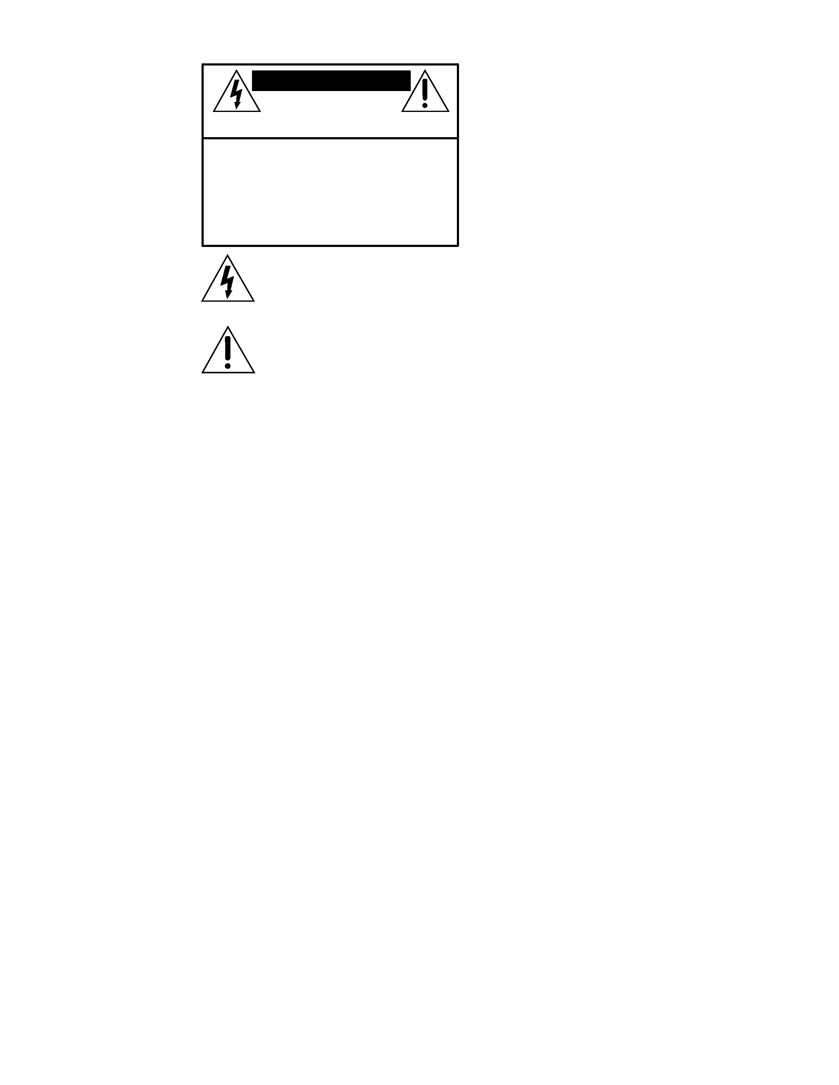
The lightning flash with arrowhead symbol within an equilateral
triangle is intended to alert the user to the presence of uninsulated
"dangerous voltage" within the product's enclosure, that may be
of sufficient magnitude to constitute a risk of electric shock to persons.
Le symbole éclair avec point de flèche à l'intérieur d'un triangle
équilatéral est utilisé pour alerter l'utilisateur de la présence à
l'intérieur du coffret de "voltage dangereux" non isolé d'ampleur
suffisante pour constituer un risque d'éléctrocution.
The exclamation point within an equilateral triangle is intended to
alert the user of the presence of important operating and maintenance
(servicing) instructions in the literature accompanying the appliance.
Le point d'exclamation à l'intérieur d'un triangle équilatéral est
employé pour alerter les utilisateurs de la présence d'instructions
importantes pour le fonctionnement et l'entretien (service) dans le
livret d'instruction accompagnant l'appareil.
10. Damage Requiring Service -- This Mackie product should
be serviced only by qualified service personnel when:
A. The power-supply cord or the plug has been
damaged; or
B. Objects have fallen, or liquid has spilled into
this Mackie product; or
C. This Mackie product has been exposed to rain;
or
D. This Mackie product does not appear to operate
normally or exhibits a marked change in
performance; or
E. This Mackie product has been dropped, or its
chassis damaged.
11. Servicing -- The user should not attempt to service this
Mackie product beyond those means described in this
operating manual. All other servicing should be referred to the
Mackie Service Department.
12. To prevent electric shock, do not use this polarized plug
with an extension cord, receptacle or other outlet unless the
blades can be fully inserted to prevent blade exposure.
Pour préevenir les chocs électriques ne pas utiliser cette fiche
polariseé avec un prolongateur, un prise de courant ou une autre
sortie de courant, sauf si les lames peuvent être insérées à fond
sans laisser aucune pariie à découvert.
13. Grounding or Polarization -- Precautions should be taken
so that the grounding or polarization means of this Mackie
product is not defeated.
14. This apparatus does not exceed the Class A/Class B
(whichever is applicable) limits for radio noise emissions from
digital apparatus as set out in the radio interference
regulations of the Canadian Department of Communications.
ATTENTION --Le présent appareil numérique n'émet pas de
bruits radioélectriques dépassant las limites applicables aux
appareils numériques de class A/de class B (selon le cas)
prescrites dans le règlement sur le brouillage radioélectrique
édicté par les ministere des communications du Canada.
15. To prevent hazard or damage, ensure that only
microphone cables and microphones designed to IEC 268-15A
are connected.
WARNING -- To reduce the risk of fire or electric shock, do
not expose this appliance to rain or moisture.
SAFETY INSTRUCTIONS
1. Read Instructions -- All the safety and operation
instructions should be read before this Mackie product is
operated.
2. Retain Instructions -- The safety and operating instruc-
tions should be kept for future reference.
3. Heed Warnings -- All warnings on this Mackie product and
in these operating instructions should be followed.
4. Follow Instructions -- All operating and other instructions
should be followed.
5. Water and Moisture -- This Mackie product should not be
used near water for example, near a bathtub, washbowl,
kitchen sink, laundry tub, in a wet basement, near a
swimming pool, swamp or salivating St. Bernard dog, etc.
6. Heat -- This Mackie product should be situated away
from heat sources such as radiators, or other devices which
produce heat.
7. Power Sources -- This Mackie product should be
connected to a power supply only of the type described in
these operation instructions or as marked on this Mackie
product.
8. Power Cord Protection -- Power supply cords should be
routed so that they are not likely to be walked upon or
pinched by items placed upon or against them, paying
particular attention to cords at plugs, convenience receptacles,
and the point where they exit this Mackie product.
9. Object and Liquid Entry -- Care should be taken so that
objects do not fall into and liquids are not spilled into the
inside of this Mackie product.
3
We realize that you must be dying to try out
your new 1202-VLZ PRO. Or you might be one of
those people who never read manuals. Either
way, all we ask is that you read this page NOW,
and the rest can wait until you're good and ready.
But do read it -- you'll be glad you did.
Other Nuggets of Wisdom
For optimum sonic performance, the channel
GAIN knobs and the MAIN MIX knob should be
set near the "
U" (unity gain) markings.
Always turn the
MAIN MIX and CONTROL
ROOM/SUBMIX level controls down before
making connections to and from your
1202-VLZ PRO.
If you shut down your equipment, turn off
your amplifier(s) first. When powering up, turn
on your amplifier(s) last.
Save the shipping box! You may need it
someday, and you don't want to have to pay for
another one.
INSTANT MIXING
Here's how to get going
right away, assuming you own a
microphone and a keyboard:
1. Plug your microphone into channel
1's MIC
input.
2. Turn on the 1202-VLZ PRO.
3. Perform the Level-Setting Procedure
.
4. Connect cords from the
MAIN OUTS(XLR,1/4"or
RCA, your choice) to your amplifier.
5. Hook up speakers to the amp and turn it on.
6. Turn up the 1202-VLZ PRO's channel
1 GAIN
knob to the center detent and the
MAIN MIX
knob one quarter of the way up.
7. Sing like a canary!
8. Plug your keyboard into stereo channel
5-6.
9. Turn that channel's
GAIN knob to the center
detent.
10. Play like a madman and sing like a canary!
It's your first mix!
READ THIS PAGE!!!
Please write your serial number here for
future reference (i.e. insurance claims,
tech support, return authorization, etc.):
LEVEL-SETTING PROCEDURE
Message to seasoned pros: do not set
levels using the old "Turn the trim up until
the clip light comes on, then back off a
hair" trick. When a Mackie Designs mixer
clip light comes on, you really are about to
clip. We worked and slaved to come up
with a better system, one that provides low
noise and high headroom.
Adjusting input levels (Chs. 14 only)
On the first four channels, it's not even
necessary to hear what you're doing to set
optimal levels. But if you'd like to: Plug
headphones into the
PHONES jack, then
set the
CONTROL ROOM/SUBMIX knob
about one-quarter of the way up.
The following steps must be performed
one channel at a time:
1. Turn the
TRIM, GAIN and AUX send
knobs fully down (counterclockwise).
2. Set the
EQ knobs at the center detent.
3. Connect the signal source to the input.
4. Engage (push in) the
SOLO switch.
5. Play something into the selected input.
This could be an instrument, a singing
or speaking voice, or a line input such
as a CD player or tape recorder output.
Be sure that the volume of the input is
the same as it would be during normal
use. If it isn't, you might have to
readjust these levels during the middle
of the set.
6. Adjust the channel's
TRIM control so
that the display on the right LED
meter stays around "
0" and never goes
higher than "
+7."
7. If you'd like to apply some
EQ, do so now
and return to step 6.
8. Disengage that channel's
SOLO switch.
9. Repeat for each of channels
1
through
4.
Part No. 820-028-01 Rev. B 06/99
©1999 Mackie Designs Inc., All Rights Reserved. Printed in the U.S.A.
Purchased at:
Date of Purchase:
4
U
O
O
+15
U
O
O
+15
U
+15
-15
U
+12
-12
U
+15
-15
LR
+20dB
O
O
+20dB
O
O
+20dB
O
O
+20dB
O
O
+20dB
O
O
+20dB
O
O
+20dB
O
O
U
O
O
+10
U
O
O
+20
U
O
O
+20
+20dB
O
O
MAX
O
O
+10dB
O
O
U
O
O
+15
U
O
O
+15
U
+15
-15
U
+12
-12
U
+15
-15
LR
U
O
O
+15
U
O
O
+15
U
+15
-15
U
+12
-12
U
+15
-15
LR
U
O
O
+15
U
O
O
+15
U
+15
-15
U
+12
-12
U
+15
-15
LR
U
O
O
+15
U
O
O
+15
U
+15
-15
U
+12
-12
U
+15
-15
LR
U
O
O
+15
U
O
O
+15
U
+15
-15
U
+12
-12
U
+15
-15
LR
U
O
O
+15
U
O
O
+15
U
+15
-15
U
+12
-12
U
+15
-15
LR
U
O
O
+15
U
O
O
+15
U
+15
-15
U
+12
-12
U
+15
-15
LR
11 12
MUTE
9 10
MUTE
7 8
MUTE
5 6
MUTE
4
MUTE
3
MUTE
2
MUTE
1
MUTE
HI
12kHz
MID
2.5kHz
LOW
80Hz
EQ
AUX
PAN
PRE FADER
SOLO
PRE FADER
SOLO
PRE FADER
SOLO
PRE FADER
SOLO
PRE FADER
SOLO
PRE FADER
SOLO
PRE FADER
SOLO
PRE FADER
SOLO
1
2
POWER
AUX 1 MASTER
AUX
RETURN
1
2
LINE IN 1
LINE IN 2
LINE IN 3
LINE IN 4
L
MONO
L
MONO
L
MONO
L
MONO
PHONES
LINE IN 5-6
R
R
R
R
AUX SEND
TAPE
INPUT
TAPE
OUTPUT
L
R
1
2
1
2
RIGHT
L
R
RIGHT
MIC
1
MIC
2
MIC
3
MIC
4
LEFT
LEFT/MONO
STEREO AUX RETURN
MAIN OUT
BAL/UNBAL
LINE IN 7-8
LINE IN 9-10
LINE IN 11-12
GAIN
GAIN
GAIN
GAIN
GAIN
GAIN
GAIN
GAIN
MAIN MIX
/SUBMIX
ALT 3-4
ALT 3-4
ALT 3-4
ALT 3-4
ALT 3-4
ALT 3-4
ALT 3-4
ALT 3-4
BAL
OR
UNBAL
BAL
OR
UNBAL
BAL
OR
UNBAL
BAL
OR
UNBAL
BAL
OR
UNBAL
BAL
OR
UNBAL
BAL
OR
UNBAL
BAL
OR
UNBAL
ALL BAL/UNBAL
EFX TO
MONITOR
MON/
EFX
1
MON/
EFX
1
MON/
EFX
1
MON/
EFX
1
MON/
EFX
1
MON/
EFX
1
MON/
EFX
1
MON/
EFX
EFX
HI
12kHz
MID
2.5kHz
LOW
80Hz
EQ
AUX
PAN
2
EFX
HI
12kHz
MID
2.5kHz
LOW
80Hz
EQ
AUX
PAN
2
EFX
HI
12kHz
MID
2.5kHz
LOW
80Hz
EQ
AUX
PAN
2
EFX
HI
12kHz
MID
2.5kHz
LOW
80Hz
EQ
AUX
PAN
2
EFX
HI
12kHz
MID
2.5kHz
LOW
80Hz
EQ
AUX
PAN
2
EFX
HI
12kHz
MID
2.5kHz
LOW
80Hz
EQ
AUX
PAN
2
EFX
HI
12kHz
MID
2.5kHz
LOW
80Hz
EQ
AUX
PAN
2
EFX
NORMALLED
PRE
POST
AUX 1
SELECT
CTL ROOM
U
U
U
U
U
U
U
U
U
U
LOW CUT
75 Hz
18dB/OCT
TRIM
+15dB -45dB
M
IC GAIN
0
U
60
-10dBV
LOW CUT
75 Hz
18dB/OCT
TRIM
+15dB -45dB
M
IC GAIN
0
U
60
-10dBV
LOW CUT
75 Hz
18dB/OCT
TRIM
+15dB -45dB
M
IC GAIN
0
U
60
-10dBV
LOW CUT
75 Hz
18dB/OCT
TRIM
+15dB -45dB
M
IC GAIN
0
U
60
-10dBV
RUDE
SOLO
LIGHT
LEVEL
SET
CONTROL
ROOM
SOURCE
ALT 34
TAPE
MAIN MIX
CLIP
LEFT RIGHT
0dB=0dBu
ASSIGN
TO MAIN MIX
28
10
7
4
2
0
2
4
7
10
20
30
XDR
MIC PR
E
XDR
MIC PR
E
XDR
MIC PR
E
XDR
MIC PR
E
OUTPUT
SECTION
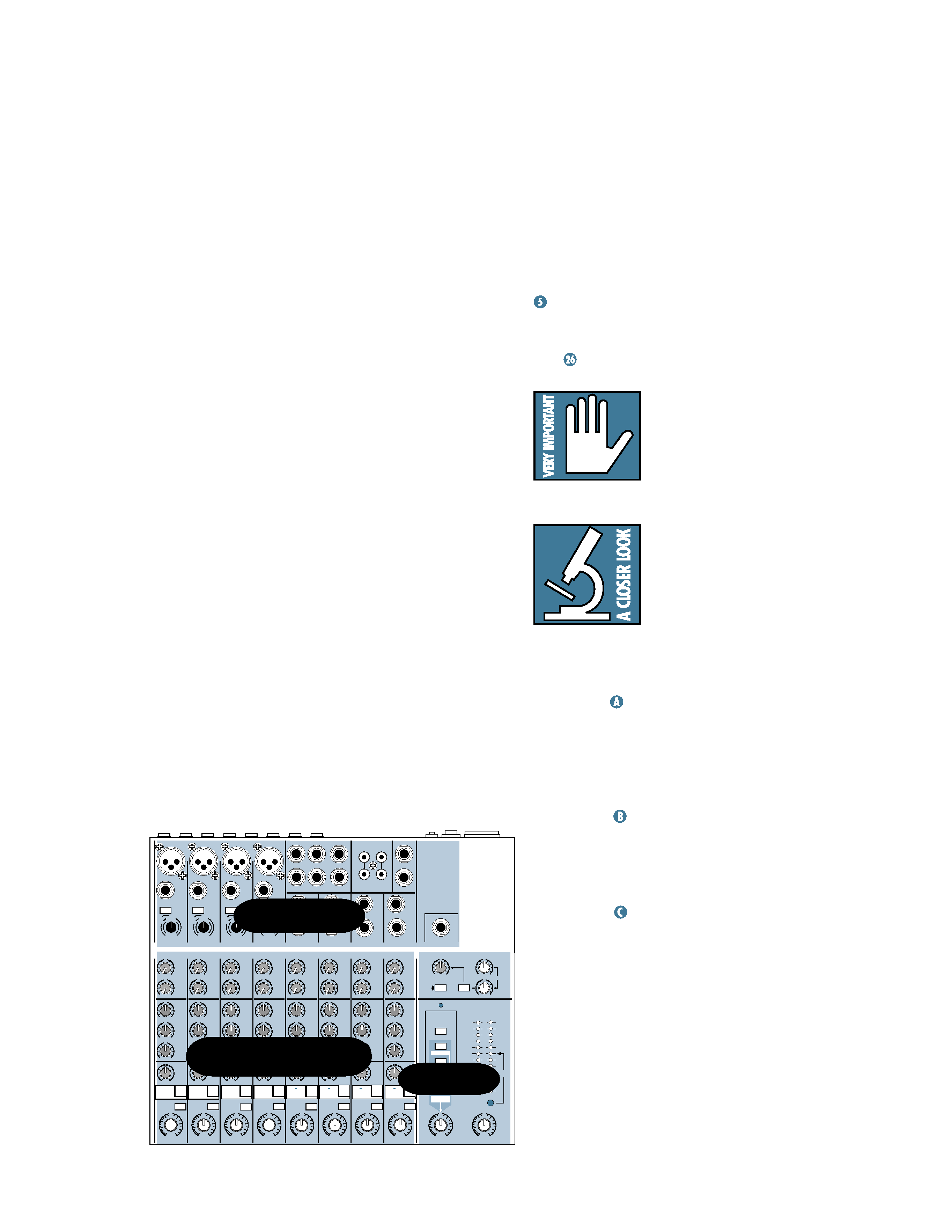
CHANNEL STRIPS
PATCHBAY
INTRODUCTION
Thank you for choosing a Mackie Designs
professional compact mixer. The 1202-VLZ PRO
is equipped with our new precision-engineered
XDRTM Extended Dynamic Range premium
studio-grade mic preamp featuring:
· Full gain range from 0 to 60dB
· +22 dBu line signal handling capability
· 130 dB dynamic range
· Distortion less than 0.0007%, 20Hz to 20kHz
· Bullet-proof RF rejection using DC pulse
transformer circuitry
· Made in Woodinville, Washington, USA
Now that you have your 1202-VLZ PRO, find
out how to get the most from it. That's where
this manual comes in.
HOW TO USE THIS MANUAL
Since many of you folks will want to hook up
your 1202-VLZ PRO immediately, the first pages
you will encounter after the table of contents
are the ever popular hookup diagrams. These
show typical mixer setups for Record/Mixdown,
Video, Disc Jockey and Stereo PA. After this
section is a detailed tour of the entire mixer.
Every feature of the 1202-VLZ PRO is described
"geographically;" in other words, in order of where
it is physically placed on the mixer's top or rear
panel. These descriptions are divided into the first
three manual chapters, just as your mixer is
organized into three distinct zones:
1. PATCHBAY: The patchbay along the top
and back.
2. CHANNEL STRIP: The eight channel
strips on the left.
3. OUTPUT SECTION: The output section on
the right.
Throughout these chapters you'll find illus-
trations, with each feature numbered. If you're
curious about a feature, simply locate it on the
appropriate illustration, notice the number
attached to it, and find that number in the
nearby paragraphs.
You'll also find cross-references to these
numbered features within a paragraph. For in-
stance, if you see "
To wire your own cables:
," simply find that number in the manual
and you've found your answer.
Finally, you'll notice feature numbers like
this:
. These numbers direct you to relevant
information.
This icon marks infor-
mation that is critically
important or unique to the
1202-VLZ PRO. For your
own good, read them and re-
member them. They will be on the final test.
This icon will lead you to
in-depth explanations of
features and practical tips.
While not mandatory, they
usually have some valuable
nugget of information.
THE GLOSSARY: A HAVEN OF
NON-TECHINESS FOR THE NEOPHYTE
Appendix
is a fairly comprehensive
dictionary of pro-audio terms. If terms like "clip-
ping," "noise floor," or "unbalanced" leave you
blank, flip to this glossary for a quick explanation.
A PLUG FOR THE CONNECTORS SECTION
Appendix
is a section on connectors:
XLR connectors, balanced connectors, unbal-
anced connectors, special hybrid connectors.
ARCANE MYSTERIES ILLUMINATED
Appendix
discusses some of the down 'n'
dirty practical realities of microphones, fixed
installations, grounding, and balanced versus
unbalanced lines. It's a goldmine for the neo-
phyte and even the seasoned pro might learn a
thing or two.

5
CONTENTS
LEVEL-SETTING PROCEDURE ..................................... 3
HOOKUP DIAGRAMS .............................................. 6
PATCHBAY DESCRIPTION ...................................... 10
MIC INPUTS ................................................... 10
PHANTOM POWER ........................................ 10
LINE INPUTS .................................................. 10
LOW CUT ....................................................... 11
TRIM ............................................................. 11
STEREO LINE INPUTS ...................................... 12
EFFECTS: SERIAL OR PARALLEL? ..................... 12
INSERT ........................................................... 13
AUX RETURNS ............................................... 13
TAPE IN .......................................................... 14
XLR MAIN OUTS ............................................ 14
XLR MAIN OUTPUT LEVEL SWITCH ................. 15
1/4" MAIN OUTS ............................................. 15
TAPE OUTPUT ................................................ 15
PHONES ......................................................... 16
ALT 3-4 .......................................................... 16
CONTROL ROOM............................................ 16
AUX SEND 1 & 2 ............................................ 16
POWER CONNECTION .................................... 17
FUSE .............................................................. 17
POWER SWITCH ............................................ 17
PHANTOM SWITCH ........................................ 17
CHANNEL STRIP DESCRIPTION .............................. 18
"U" LIKE UNITY GAIN .................................... 18
GAIN ............................................................. 18
PRE-FADER SOLO ........................................... 18
MUTE/ALT 3-4 ............................................... 18
PAN ............................................................... 19
CONSTANT LOUDNESS ! ! ! .............................. 19
3-BAND EQ .................................................... 19
AUX SEND ..................................................... 20
OUTPUT SECTION DESCRIPTION ............................ 21
MAIN MIX ..................................................... 21
VLZ MIX ARCHITECTURE ................................ 21
SOURCE MATRIX ............................................ 21
CONTROL ROOM / SUBMIX .......................... 22
PRE-FADER SOLO (PFL) .................................. 22
RUDE SOLO LIGHT .......................................... 23
ASSIGN TO MAIN MIX ................................... 23
METERS ......................................................... 23
AUX TALK ...................................................... 24
AUX 1 PRE/POST SELECT ............................... 24
AUX 1 MASTER .............................................. 24
AUX RETURNS ............................................... 25
EFX TO MONITOR .......................................... 25
JACK NORMALLING ....................................... 25
MODIFICATIONS ................................................... 26
BLOCK DIAGRAM .................................................. 29
GAIN STRUCTURE DIAGRAM ................................. 30
SPECIFICATIONS .................................................... 31
SERVICE INFO ....................................................... 32
APPENDIX: Glossary of Pro Audio Terms ................ 33
APPENDIX: Connections ......................................... 42
APPENDIX: Balanced Lines, Phantom Powering,
Grounding and Other Arcane Mysteries ......................... 45