STEREO CASSETTE DECK
X-S300
SERVICE MANUAL
© 1997-6/B51- 5325-00 (K/K) 2147
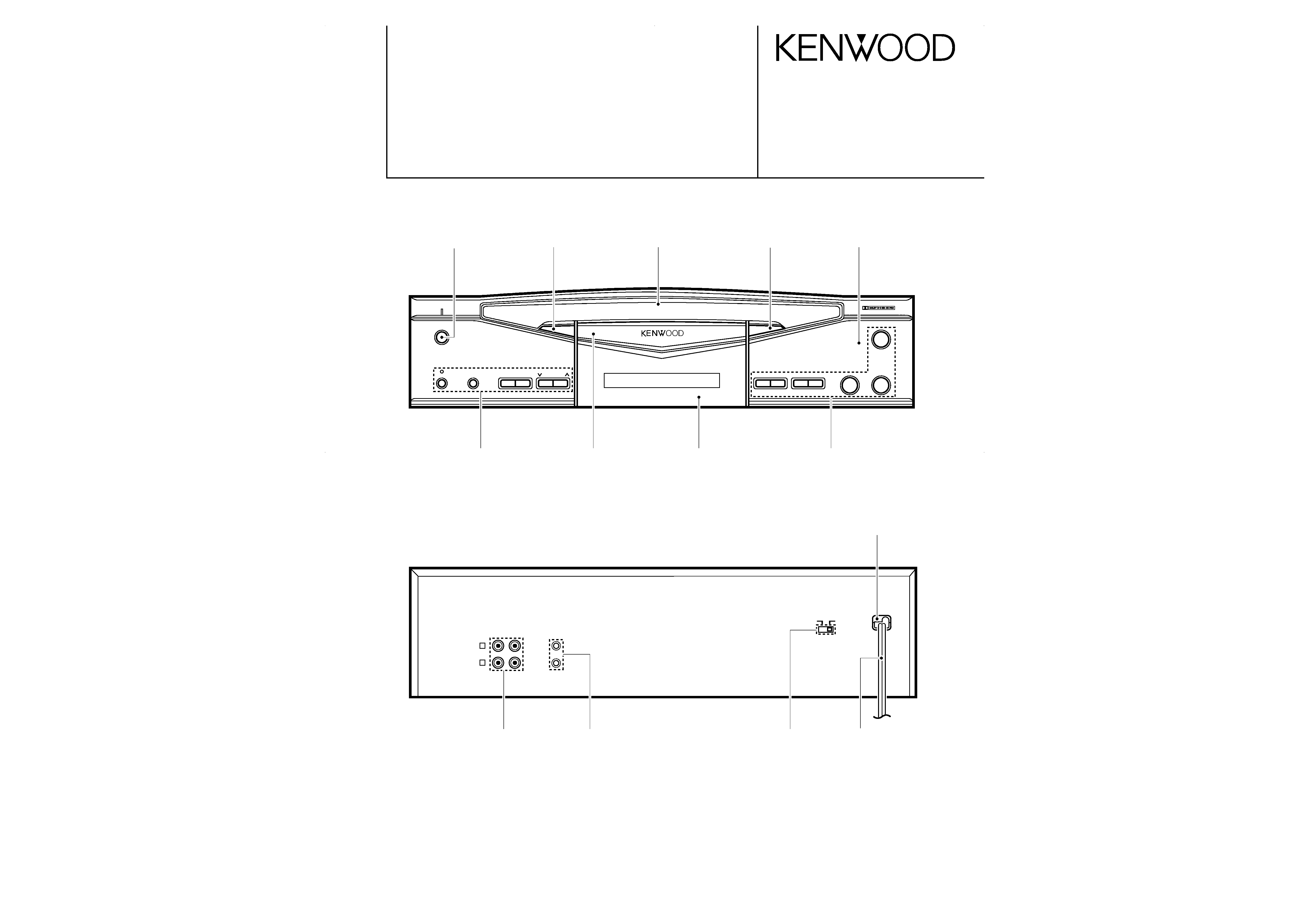
STEREO CASSETTE DECK X-S300
POWER
O.T.E.
1
0
¡
8
2
3
CCRS
COUNTER
RESET
REV.
MODE
REC LEVEL
DOLBY
- ON OFF
7
R
L
REC
IN
PLAY
OUT
SYSTEM
CONTROL
AC 110 -
120V ~
AC 220 -
240V ~
LINE
Knob
(K27-2211-04)
Knob assy
(K29-6676-04)
Escutcheon
(B07-2344-02)
Knob assy
(K29-6678-04)
Panel
(A60-1148-11)
Power cord bushing
(J42-0083-05)
Knob
(K29-6680-02)
Panel assy
(A29-0869-03)
Front glass
(B10-2356-12)
Knob
(K29-6680-02)
Phono jack
(E63-0136-05)
Miniature phone jack
(E11-0293-05)
Slide switch
(S62-0001-05)
AC power cord *
(E30-)
* Refer to parts list on page 13.
X-S300(k) COVER( 98.4.24 9:15 AM y[W 2
X-S300
2
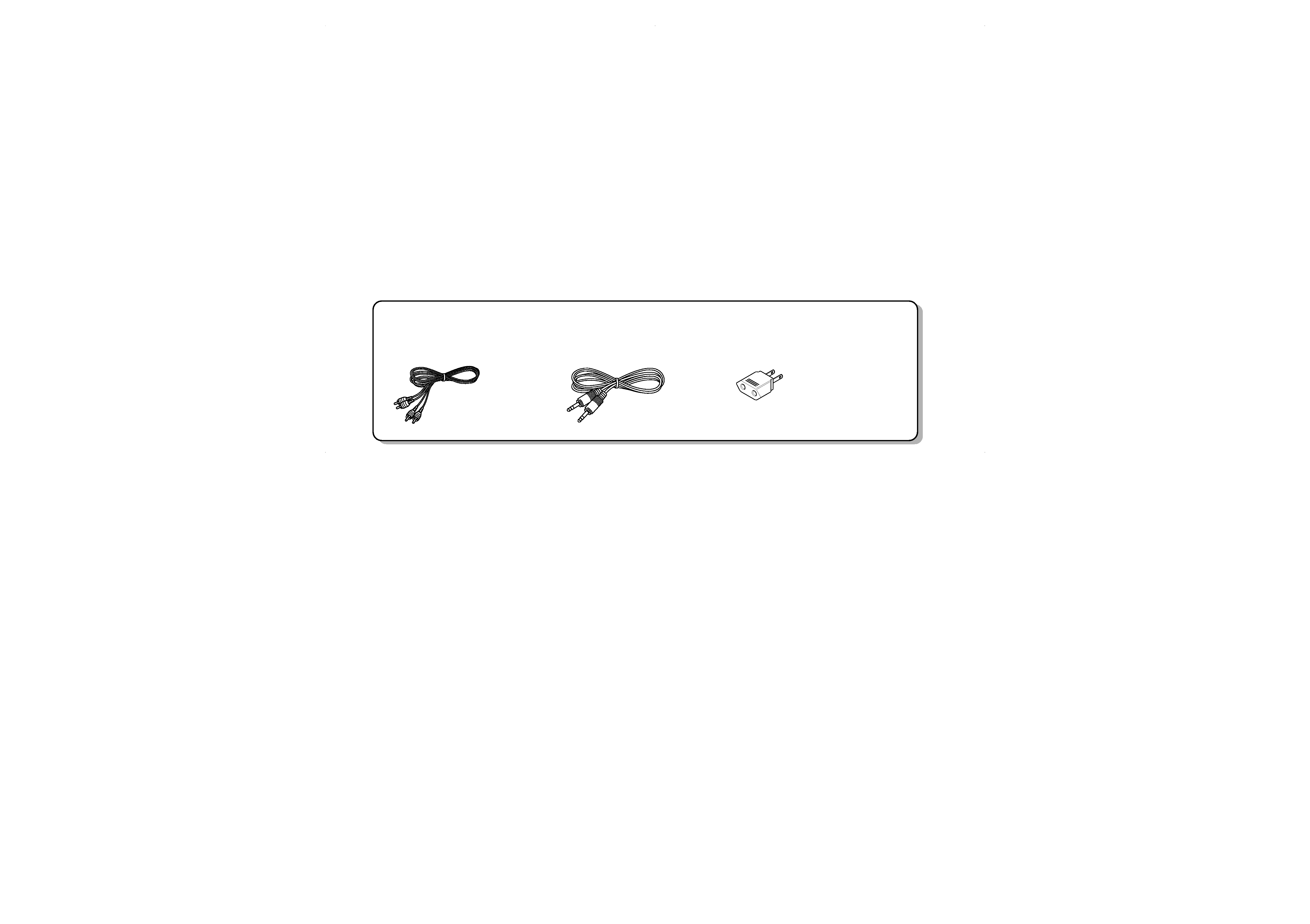
CONTENTS / ACCESSORIES
Accessories
CONTENTS / ACCESSORIES ....................................2
ADJUSTMENT .............................................................3
PARTS DESCRIPTIONS .............................................4
PC BOARD ..................................................................5
SCHEMATIC DIAGRAM ..............................................7
EXPLODED VIEW .....................................................11
PATS LIST .................................................................13
SPECIFICATIONS .....................................................17
Contents
Audio cord ......................(2)
(E30-0505-05)
System control cord ........(1)
(E30-2816-05)
* AC plug adapter ...........(1)
(E03-0115-05)
Check that the following accessories are present.
* Use to adapt the plug on the
power cord to the shape of the
wall outlet (Accessory only for
regions where use is necessary.)
X-S300(k) COVER( 98.4.24 9:15 AM y[W 3
R
L
REC
IN
PLAY
OUT
SYSTEM
CONTROL
AC 110 -
120V ~
AC 220 -
240V ~
LINE
Oscilloscope
AC voltmeter
Frequency counter
AC voltmeter
AG
{
(A)
(B)
X-S300
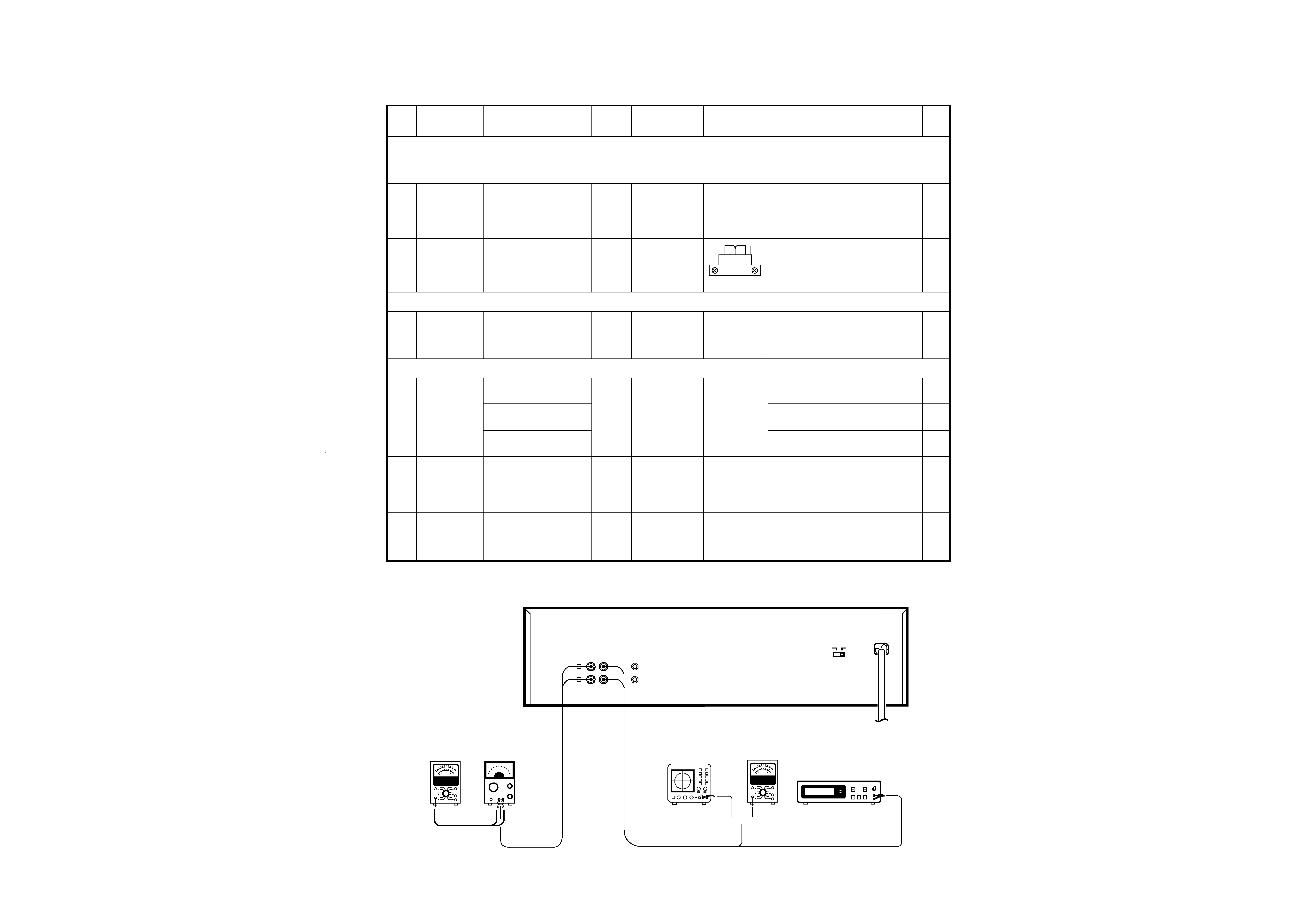
3
ADJUSTMENT
NO.
ITEM
INPUT SETTING
OUTPUT
SETTING
CASSETTE TAPE
DECK SETTING
ALIGNMENT
POINTS
ALIGN FOR
FIG.
Unless otherwise specified, set the respective switches as follows:
0dBs = 0.775V
TAPE : NORMAL
DOLBY : OFF
I
Cassette mechanism unit (Adjustment of the REC / PLAY head)
(1)
Demagnetization
and cleaning
--
--
Power : OFF
Demagnetization,
cleaning, PLAY
Recording
head, erase
head, capstan
pinch roller
Demagnetize the REC / PLAY head
with the head eraser. Clean the REC /
PLAY head, erase head, capstan and
pinch roller using a cotton swab slightly
damped with alcohol.
(2)
Azimuth of the
REC / PLAY
head
SCC-1727
TCC-153
MTT-114
10kHz, -10dB
(B)
PLAY
Adjust the output to maximum and
adjust the azimuth adjustment screw
for the Lissajours waveform pattern of
the oscilloscope to become close to a
45° straight ling.
II
PC BOARD ADJUSTMENT
(1)
TAPE SPEED
(NORMAL)
TCC-110
MTT-111
SCC-1727
3kHZ
(B)
PLAY
VR7
Adjust the tape speed so that 3kHz is
obtained at the center of the tape.
III
PC board adjustment.
(1)
PLAYBACK
LEVEL
MTT-150
400Hz
(B)
PLAY
VR 1 (L)
VR 2 (R)
Adjust the playback output to 1dBs.
MTT-256, SCC-1727
315Hz
Adjust the playback output to 4dBs.
MTT-256U, TCC-120
315 Hz
Adjust the playback output to 0 dBs.
(2)
BIAS CURRENT
(A)
Adjust the AG for the
output of the DECK to
become 12.5KHz 20dBs.
400Hz/12.5kHz (AC-224)
(B)
REC PLAY
VR 3 (L)
VR 4 (R)
Record 400Hz and 12.5kHz alternately,
and adjust the bias current adjustment
potentiometer for the playback levels to
become the same.
(3)
RECORDING
LEVEL
(A)
Adjust the AG for the
output of the DECK to
become 1kHz 20dBs.
(B)
REC PLAY
VR 5 (L)
VR 6 (R)
20 dBs
Measurement Equipment Connections
RVS
FWD
X-S300(k) COVER( 98.4.24 9:15 AM y[W 7
X-S300
4
PARTS DESCRIPTIONS
X-S300(k) COVER( 98.4.24 9:16 AM y[W 8
ACE
G
I
BD
F
H
J
2
1
3
5
7
4
6
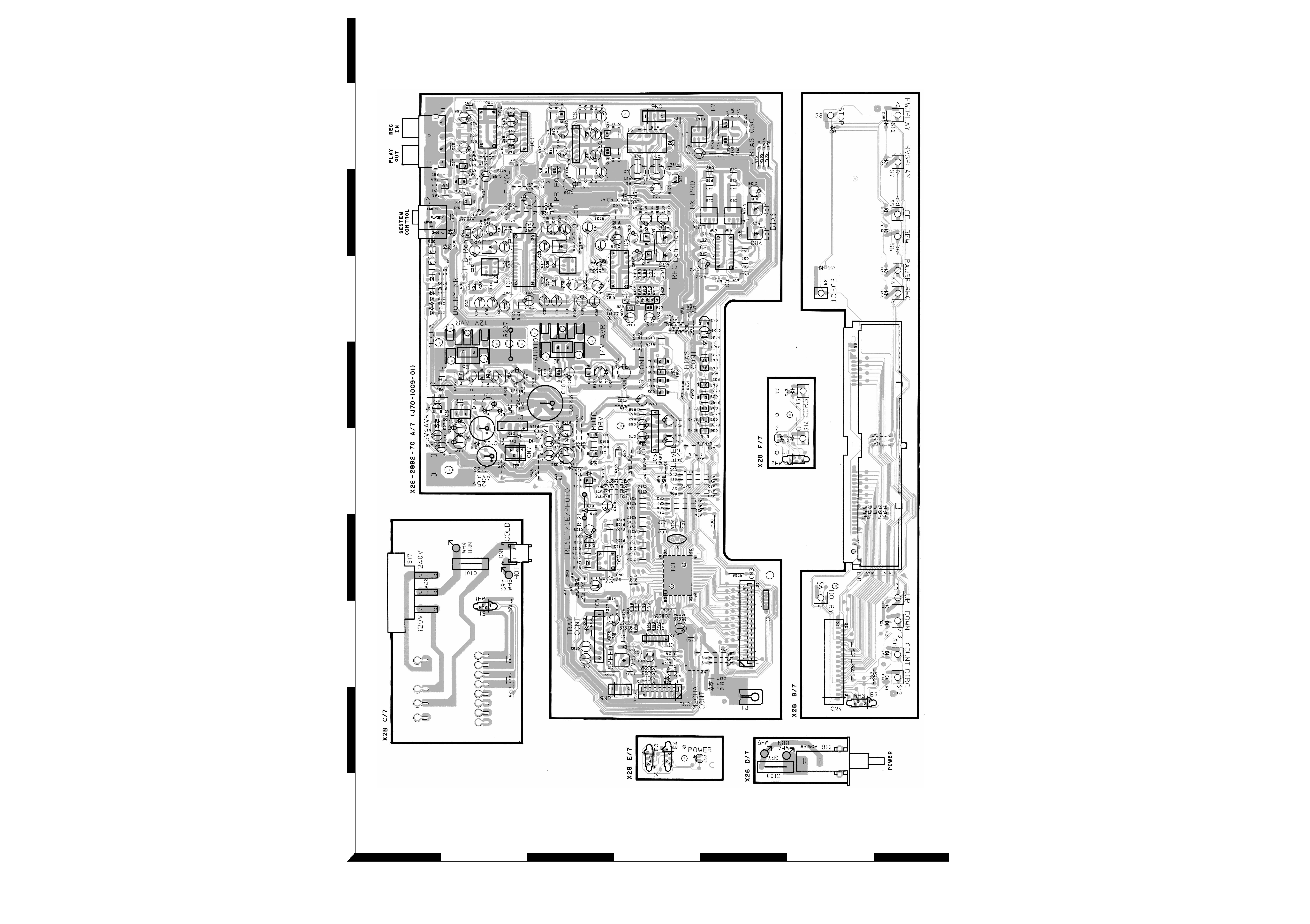
Refer to the schematic diagram for the value of resistors and capacitors.
PC BOARD(Component side view)
5
6
X28-2892-70: TE
X28-2940-20: MI
X28-2940-71: XC
X-S300(K)PCB/SD( 98.4.249:23AM y[W 2