© 2004-7 PRINTED IN JAPAN
B51-8692-00 (N) 1007
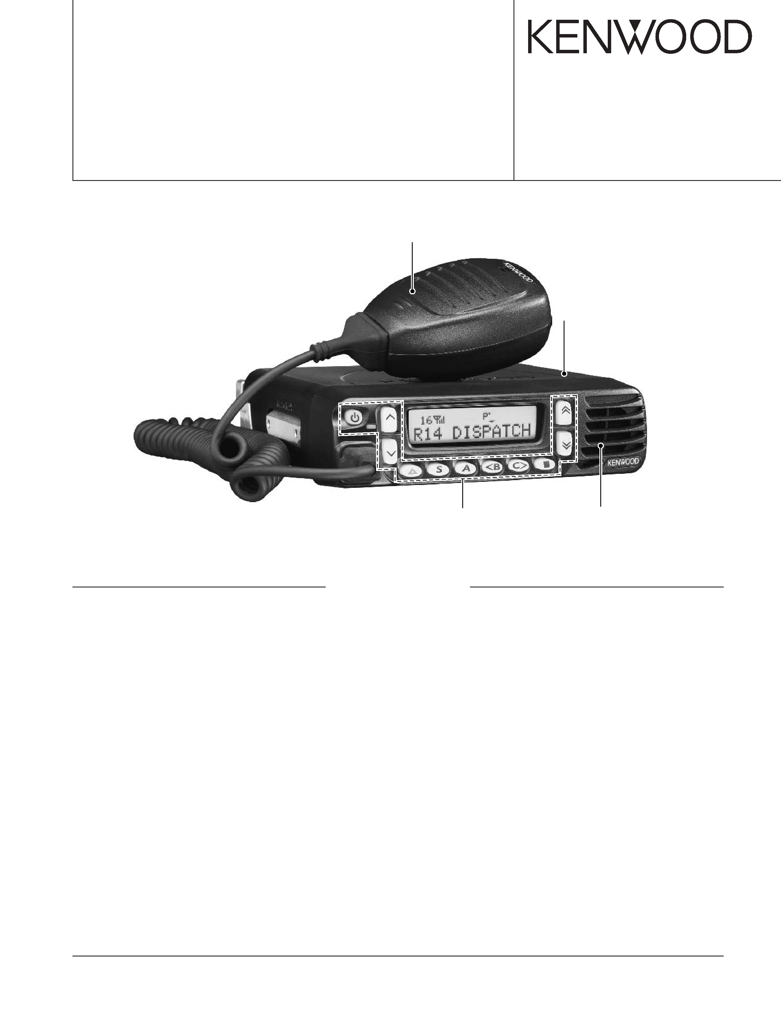
UHF FM TRANSCEIVER
TK-8180
SERVICE MANUAL
Panel assy
(A62-1094-23)
Key top
(K29-9312-21)
Cabinet
(A01-2194-11)
Microphone
(T91-0639-05)
GENERAL .................................................................. 2
SYSTEM SET-UP ...................................................... 3
REALIGNMENT ......................................................... 4
INSTALLATION ......................................................... 7
DISASSEMBLY FOR REPAIR ................................. 13
CIRCUIT DESCRIPTION .......................................... 16
SEMICONDUCTOR DATA ...................................... 20
COMPONENTS DESCRIPTION .............................. 22
PARTS LIST ............................................................. 24
EXPLODED VIEW .................................................... 33
PACKING ................................................................. 34
ADJUSTMENT ........................................................ 35
TERMINAL FUNCTION ........................................... 46
PC BOARD
DISPLAY UNIT (X54-3480-10) ............................ 50
TX-RX UNIT (X57-6990-10) (A/3, C/3) ............... 52
TX-RX UNIT (X57-6990-10) (B/3) ....................... 54
SCHEMATIC DIAGRAM
DISPLAY UNIT (X54-3480-10) ............................ 58
TX-RX UNIT (X57-6990-10) ................................ 60
INTERCONNECTION DIAGRAM ............................ 69
BLOCK DIAGRAM ................................................... 70
LEVEL DIAGRAM .................................................... 72
OPTIONAL ACCESSORIES
KRK-10 (Control Head Remote Kit: 23ft/7m) ...... 74
KAP-2 (Horn Alert/P.A. Relay unit) ................... 79
KCT-40 (Radio Interface Cable) .......................... 79
KCT-46 (Ignition Sense Cable) ........................... 79
KMC-35 (Microphone) ........................................ 79
KMC-36 (Keypad Microphone) .......................... 79
SPECIFICATIONS ................................. BACK COVER
CONTENTS

TK-8180
2
INTRODUCTION
SCOPE OF THIS MANUAL
This manual is intended for use by experienced techni-
cians familiar with similar types of commercial grade commu-
nications equipment. It contains all required service informa-
tion for the equipment and is current as of this publication
date. Changes which may occur after publication are covered
by either Service Bulletins or Manual Revisions, which are
issued as required.
ORDERING REPLACEMENT PARTS
When ordering replacement parts or equipment informa-
tion, the full part identification number should be included.
This applies to all parts : components, kits, and chassis. If the
part number is not known, include the chassis or kit number
of which it is a part and a sufficient description of the required
component for proper identification.
PERSONAL SAFETY
The following precautions are recommended for personal
safety :
·DO NOT transmit if someone is within two feet (0.6
meter) of the antenna.
·DO NOT transmit until all RF connectors are secure and
any open connectors are properly terminated.
· SHUT OFF this equipment when near electrical blasting
caps or while in an explosive atmosphere.
· All equipment should be properly grounded before power-
up for safe operation.
· This equipment should be serviced by only qualified tech-
nicians.
PRE-INSTALLATION CONSIDERATIONS
1. UNPACKING
Unpack the radio from its shipping container and check for
accessory items. If any item is missing, please contact
KENWOOD immediately.
2. LICENSING REQUIREMENTS
Federal regulations require a station license for each radio
installation (mobile or base) be obtained by the equipment
owner. The licensee is responsible for ensuring transmitter
power, frequency, and deviation are within the limits permit-
ted by the station license.
Transmitter adjustments may be performed only by a li-
censed technician holding an FCC first, second or general
class commercial radiotelephone operator's license. There is
no license required to install or operate the radio.
3. PRE-INSTALLATION CHECKOUT
3-1. Introduction
Each radio is adjusted and tested before shipment. How-
ever, it is recommended that receiver and transmitter opera-
tion be checked for proper operation before installation.
3-2. Testing
The radio should be tested complete with all cabling and
accessories as they will be connected in the final installation.
Transmitter frequency, deviation, and power output should
be checked, as should receiver sensitivity, squelch operation,
and audio output. Signaling equipment operation should be
verified.
4. PLANNING THE INSTALLATION
4-1. General
Inspect the vehicle and determine how and where the ra-
dio antenna and accessories will be mounted.
Plan cable runs for protection against pinching or crushing
wiring, and radio installation to prevent overheating.
4-2. Antenna
The favored location for an antenna is in the center of a
large, flat conductive area, usually at the roof center. The
trunk lid is preferred, bond the trunk lid and vehicle chassis
using ground straps to ensure the lid is at chassis ground.
4-3. Radio
The universal mount bracket allows the radio to be
mounted in a variety of ways. Be sure the mounting surface
is adequate to support the radio's weight. Allow sufficient
space around the radio for air cooling. Position the radio close
enough to the vehicle operator to permit easy access to the
controls when driving.
4-4. DC Power and wiring
1. This radio may be installed in negative ground electrical
systems only. Reverse polarity will cause the cable fuse to
blow. Check the vehicle ground polarity before installation
to prevent wasted time and effort.
2. Connect the positive power lead directly to the vehicle
battery positive terminal. Connecting the Positive lead to
any other positive voltage source in the vehicle is not rec-
ommended.
3. Connect the ground lead directly to the battery negative
terminal.
4. The cable provided with the radio is sufficient to handle
the maximum radio current demand. If the cable must be
extended, be sure the additional wire is sufficient for the
current to be carried and length of the added lead.
5. INSTALLATION PLANNING CONTROL STATIONS
5-1. Antenna system
Control station. The antenna system selection depends on
many factors and is beyond the scope of this manual. Your
KENWOOD dealer can help you select an antenna system
that will best serve your particular needs.
5-2. Radio location
Select a convenient location for your control station radio
which is as close as practical to the antenna cable entry point.
Secondly, use your system's power supply (which supplies
the voltage and current required for your system). Make sure
sufficient air can flow around the radio and power supply to
allow adequate cooling.
GENERAL
TK-8180
3
SERVICE
This radio is designed for easy servicing. Refer to the
schematic diagrams, printed circuit board views, and align-
ment procedures contained in this manual.
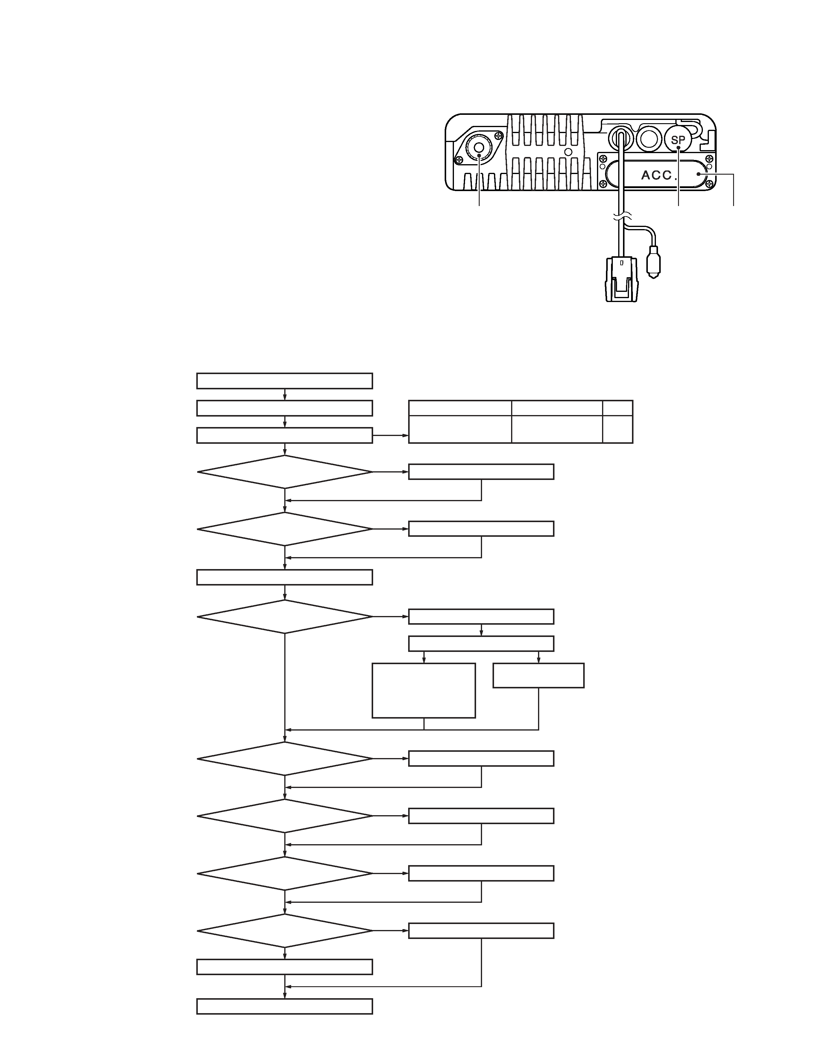
NOTE
· If you do not intend to use the speaker 3.5-mm jack and
the D-sub 25-pin connector, fit the supplied speaker-jack
cap and D-sub cap to stop dust and sand from getting in.
· If the transceiver is turned ON or OFF when the power-on/
off status message is enabled, the transceiver sends the
status.
GENERAL / SYSTEM SET-UP
Speaker
jack cap
D-sub
cap
Power input
connector
Ignition
sense cable
Antenna
connector
Merchandise received
License and frequency allocated by FCC
Choose the type of transceiver
Transceiver programming
See page 4.
A personal computer (IBM PC or compatible), programming
interface (KPG-46), and programming software (KPG-89D)
are required for programming.
Are you using
the remote kit?
Are you using
the ignition sense cable?
Are you using
the radio interface cable?
Are you using
the public address?
Are you using
the voice guide & storage
unit?
KRK-10
KCT-46
KCT-40
KCT-36 Extension cable
KGP-2A
Modem GPS receiver
or
KGP-2B
Modem GPS controller
or
KDS-100
Mobile data terminal
KAP-2
VGS-1
YES
NO
YES
NO
YES
NO
YES
NO
YES
NO
Supplied microphone
Delivery
Are you using
the external speaker?
Are you using
the keypad microphone?
KES-3 or KES-5 External speaker
KMC-32 or KMC-36
YES
NO
YES
NO
Desk top microphone KMC-9C
See page 9.
See page 7.
See page 7.
See page 8.
See page 10.
(Option)
(Option)
(Option)
(Option)
(Option)
(Option)
(Option)
(Option)
(Option)
(Option)
Frequency range
RF power
Type
450~520MHz
30W
(490~520MHz : 25W)
K
SYSTEM SET-UP
TK-8180
4
1. Modes
Mode
Function
User mode
For normal use.
Panel test mode
Used by the dealer to check the funda-
mental characteristics.
Panel tuning mode
Used by the dealer to tune the radio.
PC mode
Used for communication between the
radio and PC (IBM compatible).
Data programming
Used to read and write frequency data
mode
and other features to and from the radio.
PC test mode
Used to check the radio using the PC.
This feature is included in the FPU.
See panel test.
PC tuning mode
Used to tune the radio using the PC.
This feature is included in the FPU.
See panel tuning.
Firmware
Used when changing the main program
programming mode
of the flash memory.
Clone mode
Used to transfer programming data from
one radio to another.
Firmware version
Used to confirm the internal firmware
information
version.
Clock adjustment mode
Used to adjust date and time.
2. How to Enter Each Mode
Mode
Operation
User mode
Power ON
Panel test mode
[A] + Power ON
PC mode
Received commands from PC
Panel tuning mode
[Panel test mode] + [S]
Firmware programming mode
[S] + Power ON
Clone mode
[B] + Power ON
Firmware version information
[
] + Power ON
Clock adjustment mode
[C] + Power ON
3. Panel Test Mode
Setting method refer to ADJUSTMENT.
4. Panel Tuning Mode
Setting method refer to ADJUSTMENT.
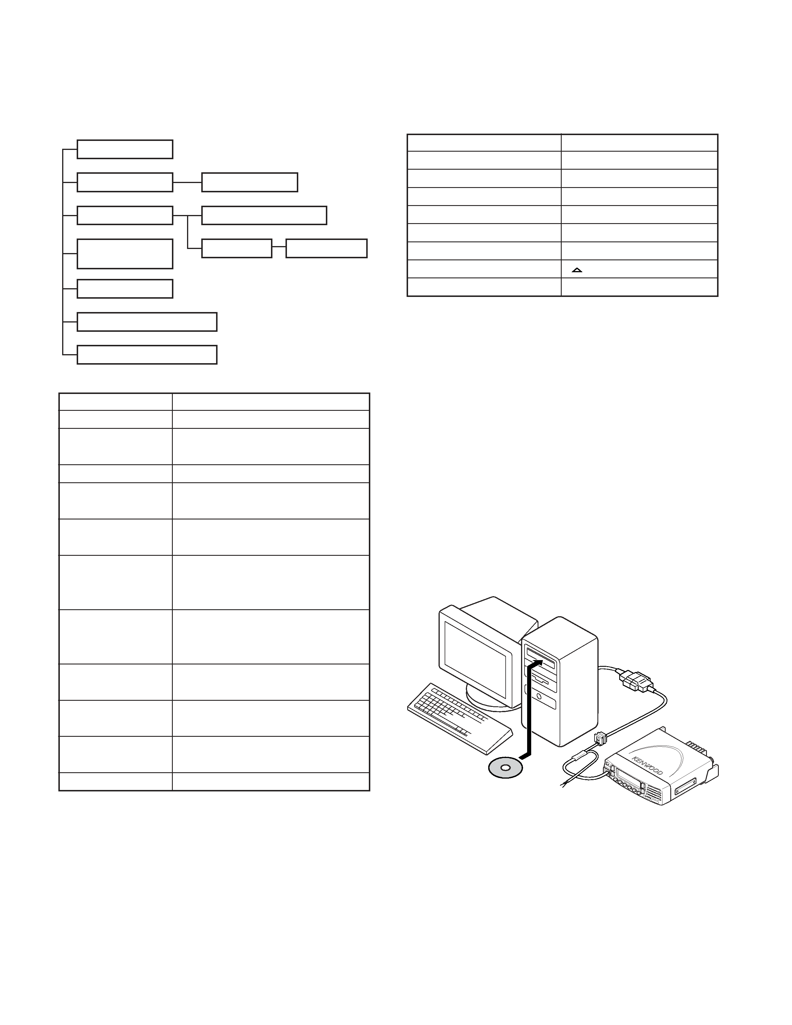
5. PC Mode
5-1. Preface
The transceiver is programmed by using a personal com-
puter, programming interface (KPG-46) and programming
software (KPG-89D).
The programming software can be used with an IBM PC
or compatible. Figure 1 shows the setup of an IBM PC for
programming.
User mode
Panel test mode
Firmware version information
Panel tuning mode
Data programming mode
PC test mode
PC tuning mode
PC mode
Clone mode
Firmware
programming mode
Clock adjustment mode
KPG-89D
IBM PC
KPG-46 or
KPG-46 +
Tuning cable
(E30-3383-05)
Fig. 1
REALIGNMENT

TK-8180
5
5-2. Connection procedure
1. Connect the transceiver to the personal computer with
the interface cable.
2. When the POWER switch on, user mode can be entered
immediately. When PC sends command the radio enter
PC mode, and "PROGRAM" is displayed on the LCD.
When data transmitting from transceiver, the red LED is
lights.
When data receiving to transceiver, the green LED is
lights.
Note:
· The data stored in the personal computer must match
model type, when it is written into the flash memory.
5-3. KPG-46 description
(PC programming interface cable: Option)
The KPG-46 is required to interface the transceiver to the
computer. It has a circuit in its D-sub connector (25-pin) case
that converts the RS-232C logic level to the TTL level.
The KPG-46 connects the modular microphone jack of the
transceiver to the computers RS-232C serial port.
5-4. Programming software KPG-89D description
The KPG-89D is the programming software for the trans-
ceiver supplied on a CD-ROM. This software runs under MS-
Windows 98, ME, Windows 2000 or XP on an IBM-PC or
compatible machine.
The data can be input to or read from the transceiver and
edited on the screen. The programmed or edited data can be
printed out. It is also possible to tune the transceiver.
6. Firmware Programming Mode
6-1. Preface
Flash memory is mounted on the transceiver. This allows
the transceiver to be upgraded when new features are re-
leased in the future. (For details on how to obtain the firm-
ware, contact Customer Service.)
6-2. Connection procedure
Connect the transceiver to the personal computer (IBM
PC or compatible) with the interface cable (KPG-46). (Con-
nection is the same as in the PC Mode.)
Note :
You can only program firmware from the 8-pin micro-
phone connector on the front panel. Using the 25-pin logic
interface on the rear panel will not work.
6-3. Programming
1. Start up the firmware programming software (Fpro.exe).
2. Set the communications speed (normally, 115200 bps)
and communications port in the configuration item.
3. Set the firmware to be updated by File name item.
4. Turn the transceiver power ON with the [S] key held
down. Then, the orange LED on the transceiver lights and
"PROG 115200" is displayed.
5. Check the connection between the transceiver and the
personal computer, and make sure that the transceiver is
in the Program mode.
6. Press write button in the window. When the transceiver
starts to receive data, the [PG] display is blinking.
7. If writing ends successfully, the checksum is calculated
and a result is displayed.
8. If you want to continue programming other transceivers,
repeat steps 4 to 7.
Notes:
· This mode cannot be entered if the Firmware Program-
ming mode is set to Disable in the Programming software.
· When programming the firmware, it is recommend to
copy the data from the floppy disk to your hard disk before
update the radio firmware.
Directly copying from the floppy disk to the radio may not
work because the access speed is too slow.
6-4. Function
1. If you press the [
] key while "PROG 115200" is dis-
played, the display changes to "PROG 19200" (The LED
blinks green) to indicate that the write speed is low speed
(19200 bps). If you press the [
] key again while "PROG
19200" is displayed, the display changes to "PROG
38400" (The LED lights red and orange alternatively). If
you press the [
] key again while "PROG 38400" is dis-
played, the display changes to "PROG 57600" (The LED
blinks orange). If you press the [
] key again while
"PROG 57600" is displayed, the display returns to "PROG
115200" (The LED lights orange).
2. If you press the [
] key while "PROG 115200" is dis-
played, the checksum is calculated, and a result is dis-
played.
If you press the [
] key again while the
checksum is displayed, "PROG 115200" is redisplayed.
Note:
Normally, write in the high-speed mode.
7. Clone Mode
Programming data can be transferred from one radio to
another by connecting them via their 8-pin microphone con-
nectors. The operation is as follows (the transmit radio is the
master and the receive radio is a slave).
1. Turn the master transceiver power ON with the [B] key
held down. If the read authorization password is set to the
transceiver, the transceiver displays "CLONE LOCK". If
the password is not set, the transceiver displays "CLONE
MODE".
2. When you enter the correct password, and "CLONE
MODE" is displayed, the transceiver can be used as the
cloning master. The following describes how to enter the
password.
REALIGNMENT