© 2000-6 PRINTED IN JAPAN
B51-8534-00 (N) 616
VHF FM TRANSCEIVER
TK-785
SERVICE MANUAL
GENERAL ................................................................. 2
OPERATING FEATURES ......................................... 3
REALIGNMENT ........................................................ 4
INSTALLATION ........................................................ 6
CIRCUIT DESCRIPTION ......................................... 14
SEMICONDUCTOR DATA ..................................... 20
DESCRIPTION OF COMPONENTS ....................... 22
PARTS LIST ............................................................ 25
EXPLODED VIEW .................................................. 40
PACKING ................................................................ 41
ADJUSTMENT ....................................................... 43
TERMINAL FUNCTION ......................................... 51
PC BOARD VIEWS
PLL/VCO (X58-471X-XX) .................................. 52
TX-RX UNIT (X57-6142-71) (A/2)..................... 53
TX-RX UNIT (X57-6142-71) (B/2) ..................... 59
TX-RX UNIT (X57-6150-21) (A/2)..................... 63
TX-RX UNIT (X57-6150-21) (B/2) ..................... 69
SCHEMATIC DIAGRAM ........................................ 73
LEVEL DIAGRAM ................................................... 89
BLOCK DIAGRAM .................................................. 93
SPECIFICATIONS ................................................... 99
CONTENTS
Cabinet (Upper)
(A01-2165-13)
Cabinet (Lower)
(A01-2166-13)
Modular jack
(E08-0877-05)
Panel assy
(A62-0642-03)
Key top
(K29-5422-02)

2
TK-785
GENERAL
INTRODUCTION
SCOPE OF THIS MANUAL
This manual is intended for use by experienced techni-
cians familiar with similar types of commercial grade com-
munications equipment. It contains all required service in-
formation for the equipment and is current as of the publica-
tion data. Changes which may occur after publication are
covered by either Service Bulletins or Manual Revisions.
These are issued as required.
ORDERING REPLACEMENT PARTS
When ordering replacement parts or equipment informa-
tion, the full part identification number should be included.
This applies to all parts : components, kits, or chassis. If the
part number is not known, include the chassis or kit number
of which it is a part, and a sufficient description of the re-
quired component for proper identification.
PERSONNEL SAFETY
The following precautions are recommended for person-
nel safety :
· DO NOT transmit if someone is within two feet (0.6
meter) of the antenna.
· DO NOT transmit until all RF connectors are verified se-
cure and any open connectors are properly terminated.
· SHUT OFF and DO NOT operate this equipment near
electrical blasting caps or in an explosive atmosphere.
· All equipment should be properly grounded before
power-up for safe operation.
· This equipment should be serviced by a qualified techni-
cian only.
PRE-INSTALLATION CONSIDERNATIONS
1. UNPACKING
Unpack the radio from its shipping container and check
for accessory items. If any item is missing, please contact
KENWOOD immediately.
2. PRE-INSTALLATION CHECKOUT
2-1. Introduction
Each radio is adjusted and tested before shipment. How-
ever, it is recommended that receiver and transmitter op-
eration be checked for proper operation before installation.
2-2. Testing
The radio should be tested complete with all cabling and
accessories as they will be connected in the final installa-
tion. Transmitter frequency, deviation, and power output
should be checked, as should receiver sensitivity, squelch
operation, and audio output. QT equipment operation
should be verified.
3. PLANNING THE INSTALLATION
3-1. General
Inspect the vehicle and determine how and where the
radio antenna and accessories will be mounted.
Plan cable runs for protection against pinching or crush-
ing wiring, and radio installation to prevent overheating.
3-2. Antenna
The favored location for an antenna is in the center of a
large, flat conductive area, usually at the roof center. The
trunk lid is preferred, bond the trunk lid and vehicle chassis
using ground straps to ensure the lid is at chassis ground.
3-3. Radio
The universal mount bracket allows the radio to be
mounted in a variety of ways. Be sure the mounting surface
is adequate to support the radio's weight. Allow sufficient
space around the radio for air cooling. Position the radio
close enough to the vehicle operator to permit easy access
to the controls when driving.
3-4. DC Power and wiring
1. This radio may be installed in negative ground electrical
systems only. Reverse polarity will cause the cable fuse
to blow. Check the vehicle ground polarity before installa-
tion to prevent wasted time and effort.
2. Connect the positive power lead directly to the vehicle
battery positive terminal. Connecting the Positive lead to
any other positive voltage source in the vehicle is not rec-
ommended.
3. Connect the ground lead directly to the battery negative
terminal.
4. The cable provided with the radio is sufficient to handle
the maximum radio current demand. If the cable must be
extended, be sure the additional wire is sufficient for the
current to be carried and length of the added lead.
3
TK-785
4. INSTALLATION PLANNING CONTROL STATIONS
4-1. Antenna system
Control station. The antenna system selection depends
on many factors and is beyond the scope of this manual.
Your KENWOOD dealer can help you select an antenna sys-
tem that will best serve your particular needs.
4-2. Radio location
Select a convenient location for your control station radio
which is as close as practical to the antenna cable entry
point. Secondly, use your system's power supply (which
supplies the voltage and current required for your system).
Make sure sufficient air can flow around the radio and power
supply to allow adequate cooling.
SERVICE
This radio is designed for easy servicing. Refer to the
schematic diagrams, printed circuit board views, and align-
ment procedures contained in this manual.
Note
When you modify your radio as described in system set-
up, take the following precaution.
The rating of pin 7 (SB) of the accessory connector cable
(KCT-19) on the rear of the radio is 13.2V (E), 13.6V (K,M).
Insert a 1A fuse if you use the SB pin for external equip-
ment.
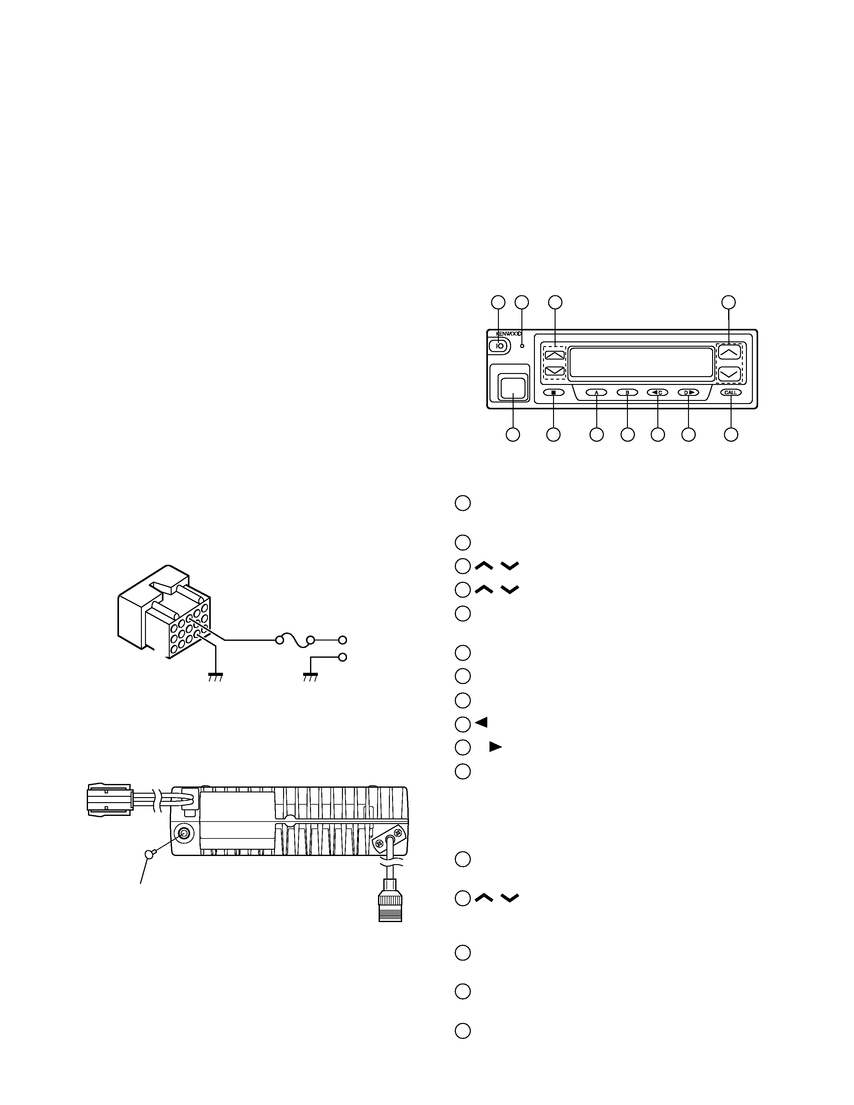
Accessory connector
cable (KCT-19)
If you do not intend to use the 3.5-mm jack for the exter-
nal speaker, fit the supplied speaker-jack cap (B09-0235-05)
to stop dust and sand getting in.
GENERAL / OPERATING FEATURES
Speaker-jack cap
(B09-0235-05)
1
3
+
7
6
13
15
OPERATING FEATURES
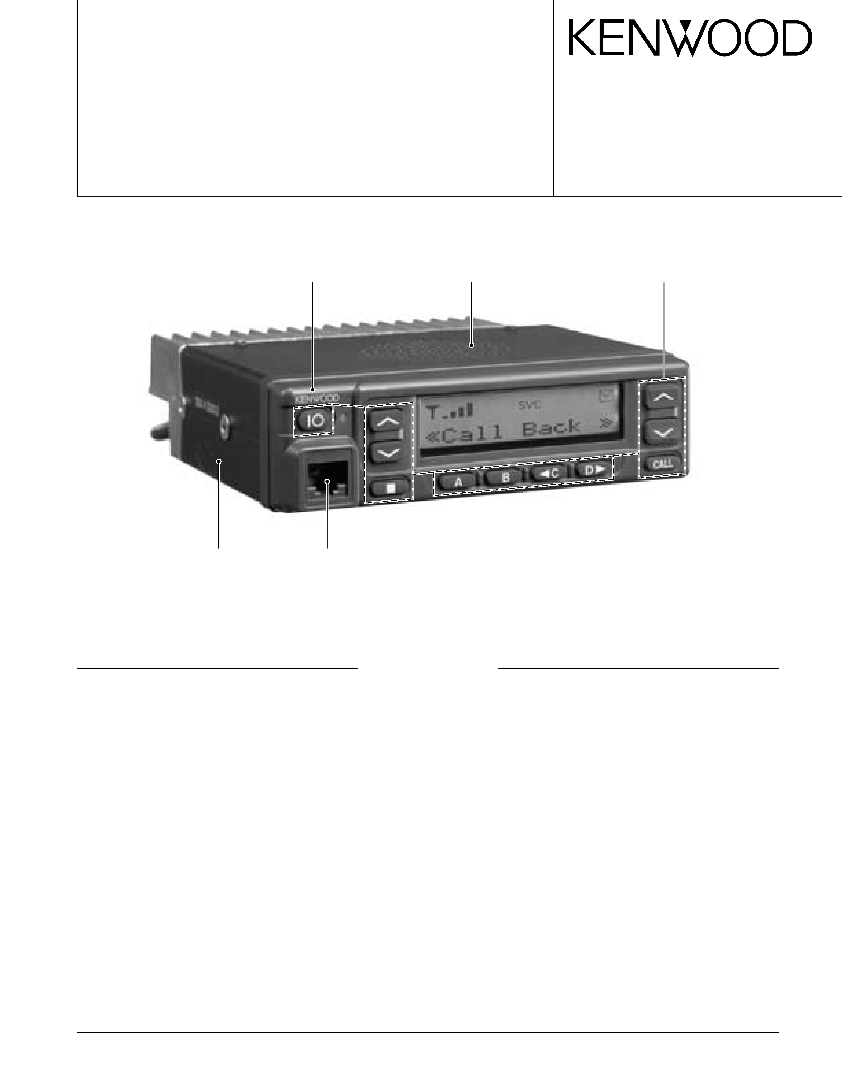
1. Transceiver Controls and Indicators (Fig. 1)
1-1. The Basics
Features listed in this section are available for both
Trunking and Conventional modes. Mode specific features
can be found in their corresponding sections in this manual.
· Front panel
1
IO (Power) switch
Press to switch the transceiver ON (or OFF).
2
Transmit/Receive indicator
3
/
(Volume) keys
4
/
(Control) keys
5
Microphone jack
Insert the microphone plug into this connector.
6 s
key
7
A key
8
B key
9
C key
10
D
key
11
CALL key
1-2. Trunking Mode
· Key functions
The numbers correspond to the Figure 1.
2
Transmit indicator
Lights red while transmitting.
4
/
(Control) keys
Press these keys to select your desired call address
(voice calls) or status (status calls).
6 s
key
Press to end the current call.
7
A key (default setting : Status/Stack)
Press to activate its auxiliary function below.
8
B key (default setting : Redial)
Press to activate its auxiliary function below.
1
2
5
6
7
8
9
11
10
34
Fig. 1
4
TK-785
OPERATING FEATURES / REALIGNMENT
REALIGNMENT
1. Modes
User mode
Panel test mode
PC mode
Firmware program-
ming mode
Panel tuning mode
Data program-
ming mode
PC test mode
PC tuning mode
Mode
Function
User mode
For normal use.
Panel test mode
Used by the dealer to check the funda-
ment characteristics.
Panel tuning mode
Used by the dealer to tune the radio.
PC mode
Used for communication between the
radio and PC (IBM compatible).
Data programming
Used to read and write frequency data
mode
and other features to and from the radio.
PC test mode
Used to check the radio using the PC.
This feature is included in the FPU.
See panel tuning.
Firmware program-
Used when changing the main program
ming mode
of the flash memory.
2. How to Enter Each Mode
Mode
Operation
User mode
Power ON
Panel test mode
[B]+Power ON
PC mode
Received commands from PC
Panel tuning mode
[Panel test mode]+[A]
Firmware programming mode
[A]+Power ON
3. Panel Test Mode
Setting method refer to ADJUSTMENT.
4. Panel Tuning Mode
Setting method refer to ADJUSTMENT.
9
C key (Default setting : None)
Press to activate its auxiliary function below. Also press
to scroll left while viewing stack entries.
10
D
key (Default setting : None)
Press to activate its auxiliary function below. Also press
to scroll right while viewing stack entries.
11
CALL key
Press to call the displayed call address.
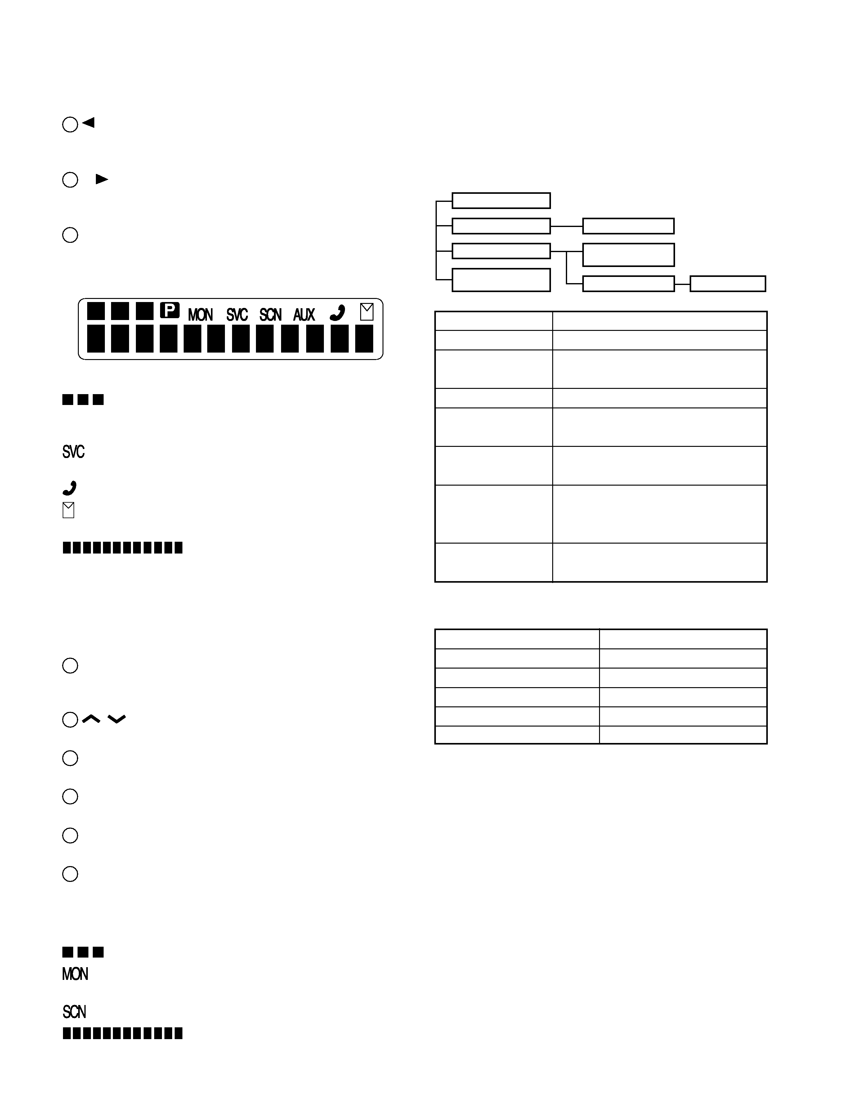
· Display
displays the strength of received signals, the output
power (high or low), status numbers, and received call
types.
appears when a control channel is found. It flashes
while the transceiver is searching for a control channel.
flashes when you activate call diversion.
appears while there is data in the stack. It flashes when
there is new data in the stack.
displays call addresses, the call dura-
tion timer, data messages, and the current operating status
of the transceiver.
1-3. Conventional Mode
· Key functions
The numbers correspond to the Figure 1.
2
Transmit/Receive indicator
Lights red while transmitting.
Lights green while receiving a signal.
4
/
(Control) keys
Press these keys to select your desired channel.
6 s
key
Press to return to Trunking mode.
7
A key
Press to turn Scan ON (or OFF).
8
B key
Press to add/remove channels to/from Scan.
11
CALL key
Press to turn the squelch OFF in order to monitor your
selected channel.
· Display (Refer to Figure 2)
displays the strength of received signals.
appears while you are monitoring a channel by press-
ing the CALL key.
appears while you are scanning.
displays channel numbers and the
current operating status of the transceiver.
Fig. 2
5
TK-785
REALIGNMENT
5. PC Mode
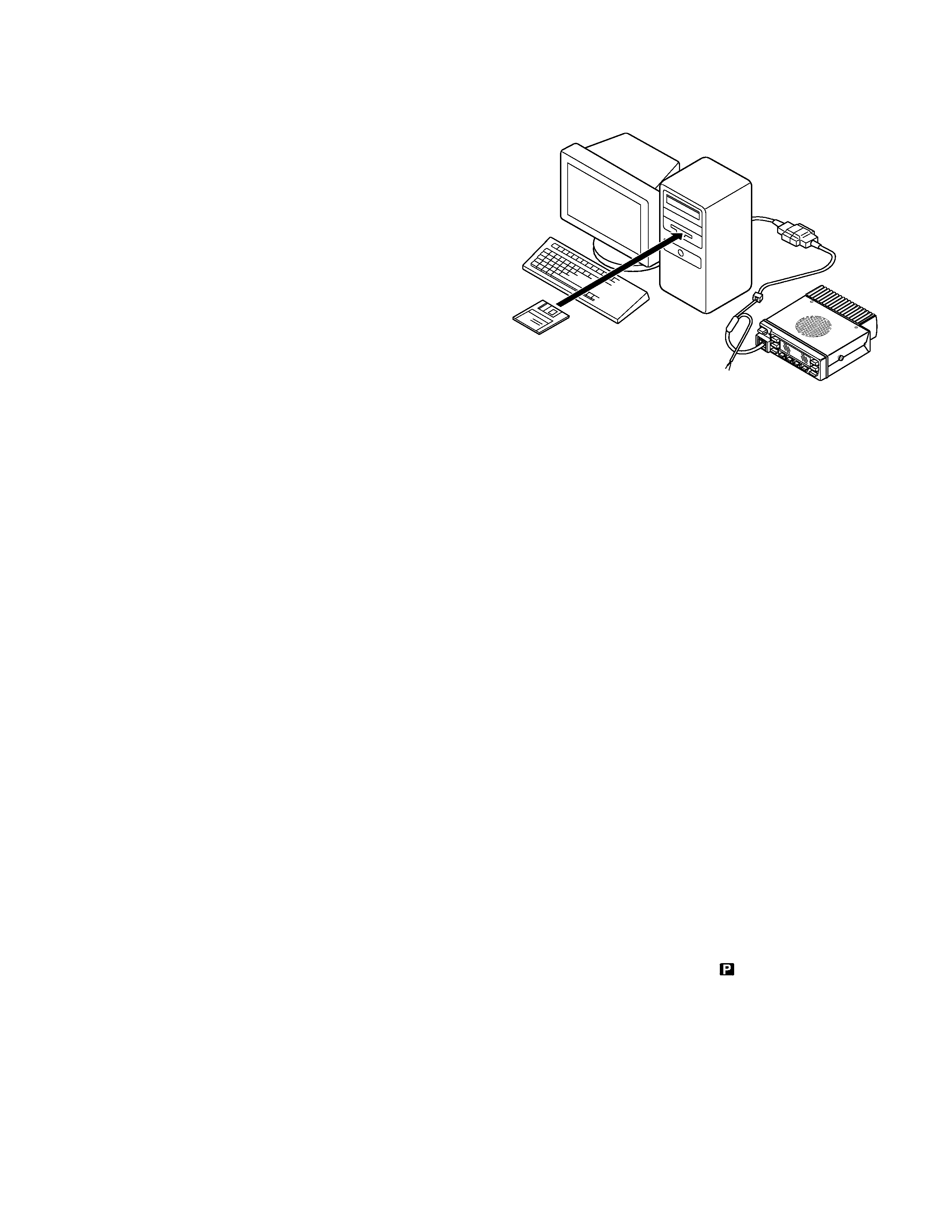
5-1. Preface
The TK-785 transceiver is programmed by using a per-
sonal computer, programming interface (KPG-46) and pro-
gramming software (KPG-62D).
The programming software can be used with an IBM PC
or compatible. Figure 1 shows the setup of an IBM PC for
programming.
5-2. Connection Procedure
1. Connect the TK-785 to the personal computer with the
interface cable.
2. When the Power switch on, user mode can be entered
immediately. When PC sends command the radio enter
PC mode, and "PROGRAM" is displayed on the LCD.
When data transmitting from transceiver, the red LED is
blinking.
When data receiving to transceiver, the green LED is
blinking.
Notes :
· The data stored in the personal computer must match
model type, when it is written into the flash memory.
· Change the TK-785 to PC mode, then attach the interface
cable.
5-3. KPG-46 Description
(PC programming interface cable : Option)
The KPG-46 is required to interface the TK-785 to the
computer. It has a circuit in its D-subconnector (25-pin) case
that converts the RS-232C logic level to the TTL level.
The KPG-46 connects the modular microphone jack of
the TK-785 to the computers RS-232C serial port.
5-4. Programming Software KPG-62D Description
The KPG-62D is the programming software for the trans-
ceiver supplied on two 3.5" floppy disks. This software runs
under MS-Windows 95/98 on an IBM-PC or compatible ma-
chine.
The data can be input to or read from the transceiver and
edited on the screen. The programmed or edited data can
be printed out. It is also possible to tune the transceiver.
We recommend that install the KPG-62D for example to
hard disk first then use it.
5-5. Programming With IBM PC
If data is transferred to the transceiver from an IBM PC
with the KPG-62D, the destination data (basic radio informa-
tion) for each set can be modified. Normally, it is not neces-
sary to modify the destination data because their values are
determined automatically when the frequency range (fre-
quency type) is set.
The values should be modified only if necessary.
Data can be programmed into the flash memory in RS-
232C format via the modular microphone jack.
KPG-46
IBM-PC
KPG-62D
TK-785
Fig. 1
6. Firmware Programming Mode
6-1. Preface
Flash memory is mounted on the TK-785. This allows the
TK-785 to be upgraded when new features are released in
the future. (For details on how to obtain the firmware, con-
tact Customer Service.)
6-2. Connection Procedure
Connect the TK-785 to the personal computer (IBM PC or
compatible) with the interface cable (KPG-46). (Connection
is the same as in the PC Mode.)
6-3. Programming
1. Start up the programming software (Fpro. exe).
2. Set the communications speed (normally, 57600 bps)
and communications port in the configuration item.
3. Set the firmware to be updated by File name item.
4. Turn the TK-785 Power ON with the [A] switch held
down. Hold the switch down until the display changes to
"PROG 57600". When "PROG 57600" appears, release
your finger from the switch.
5. Check the connection between the TK-785 and the per-
sonal computer, and make sure that the TK-785 is in the
Program mode.
6. Press write button in the window. A window opens on
the display to indicate progress of writing. When the TK-
785 starts to receive data, the
icon is blinking.
7. If writing ends successfully, the LED on the TK-785 lights
and the checksum is displayed.
8. If you want to continue programming other TK-785, re-
peat steps 4 to 7.
Tuning
cable