UHF FM TRANSCEIVER
TK-3140
© 2001-10 PRINTED IN JAPAN
B51-8603-00 (S) 1422
SERVICE MANUAL
GENERAL ................................................................................. 2
SYSTEM SET-UP ..................................................................... 2
OPERATING FEATURES ......................................................... 3
REALIGNMENT ........................................................................ 4
CIRCUIT DESCRIPTION .......................................................... 6
SEMICONDUCTOR DATA ..................................................... 12
DESCRIPTION OF COMPONENTS ....................................... 13
PARTS LIST ............................................................................ 14
EXPLODED VIEW .................................................................. 22
PACKING ................................................................................ 23
ADJUSTMENT ........................................................................ 24
TERMINAL FUNCTION .......................................................... 34
PC BOARD VIEWS
TX-RX UNIT (X57-6410-10) .............................................. 35
SCHEMATIC DIAGRAM ......................................................... 45
BLOCK DIAGRAM .................................................................. 49
LEVEL DIAGRAM ................................................................... 51
KSC-25 .................................................................................... 52
KNB-24L,KNB-25A,KNB-26N,KRA-23 .................................... 55
SPECIFICATIONS ............................................... BACK COVER
CONTENTS
Knob (ENC)
(K29-9134-03)
Knob (VOL)
(K29-9133-03)
Cabinet assy
(A02-3653-04)
Knob (PTT)
(K29-9131-03)
Antenna
(KRA-23:option)
Key top
(SW1,SW2)
(K29-9132-03)
Does not come with antenna.
Antenna is available as an option.
TK-3140
2
GENERAL / SYSTEM SET-UP
INTRODUCTION
SCOPE OF THIS MANUAL
This manual is intended for use by experienced technicians
familiar with similar types of commercial grade communications
equipment. It contains all required service information for the
equipment and is current as of the publication date. Changes
which may occur after publication are covered by either Service
Bulletins or Manual Revisions. These are issued as required.
ORDERING REPLACEMENT PARTS
When ordering replacement parts or equipment information,
the full part identification number should be included. This
applies to all parts : components, kits, or chassis. If the part
number is not known, include the chassis or kit number of which
it is a part, and a sufficient description of the required
component for proper identification.
PERSONNEL SAFETY
The following precautions are recommended for personnel
safety:
q
DO NOT transmit until all RF connectors are verified secure
and any open connectors are properly terminated.
q
SHUT OFF and DO NOT operate this equipment near
electrical blasting caps or in an explosive atmosphere.
q
This equipment should be serviced by a qualified technician only.
SERVICE
This radio is designed for easy servicing. Refer to the
schematic diagrams, printed circuit board views, and alignment
procedures contained within.
Merchandise received
License and frequency allocated by FCC
Choose the type of transceiver
Transceiver programming
Delivery
Are you using the speaker microphone?
TX/RX 450~490
4.0W
TK-3140 K
Frequency range (MHz) RF power
Type
A personal computer (IBM PC or compatible), programming
interface (KPG-36), and programming software (KPG-74D)
are required for programming.
(The frequency, trunked system features, conventional system
features, TX power HI/LOW, and signalling data are programmed
for the transceiver.)
YES
NO
KMC-25
Speaker microphone
(Option)
SYSTEM SET-UP
TK-3140
3
OPERATING FEATURES
1. Operation Features
The TK-3140 is an UHF FM radio designed to operate in
both trunking format and conventional format. The
programmable features are summarized.
Model
Trunking Format
Trunking mode
Conventional Format
Conventional mode
s Trunking Format
This format can handle up to 32 systems with up to 250
groups in each system. The transceiver can be used in both
trunked mode and conventional mode. Systems, groups,
and their functions are programmed.
s Conventional Format
This format can handle up to 250 groups with 250 channels
in each group.
The transceiver can be used only in conventional mode.
Groups, channels, and their functions are programmed.
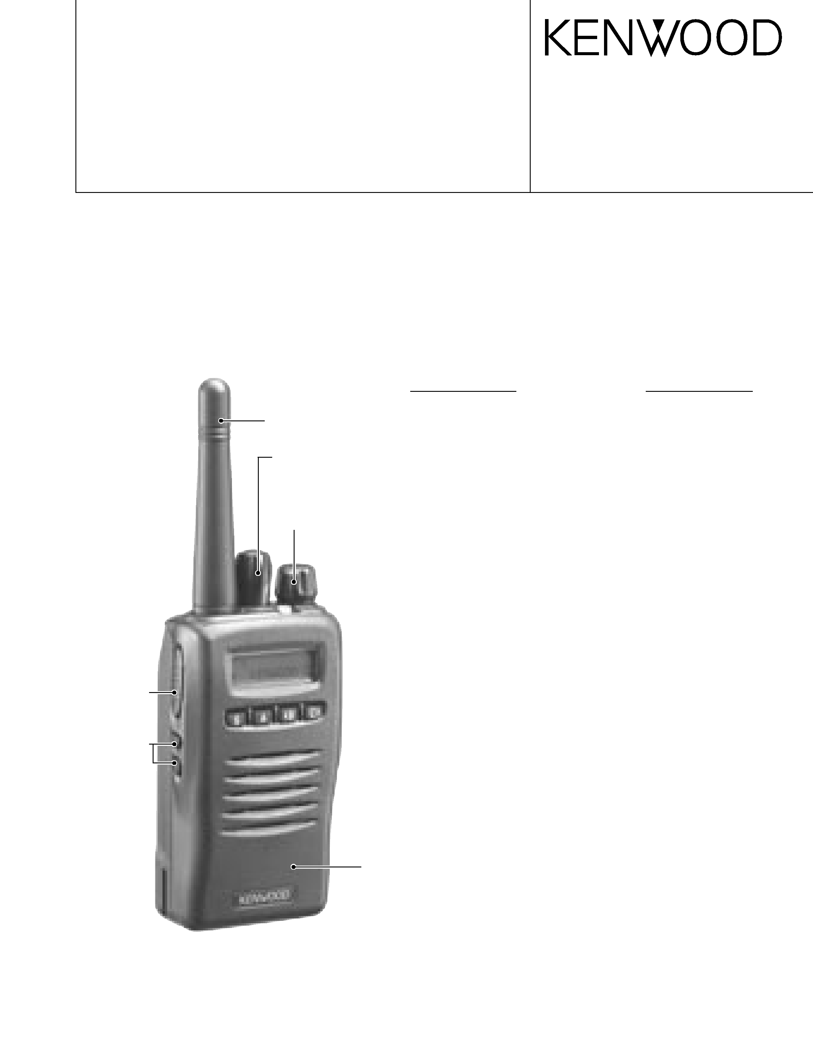
2. Transceiver Controls and Indicators
2-1. Physical Layout
3
2
57
11
10
8
4
16
9
1 Antenna connector
Connect an (optional) antenna here.
2 Rotary encoder
Rotate this encoder to activate its programmable function.
(System or Group Up/ Down in Trunking Format, and Group
or Channel Up/ Down in Conventional Format.) For further
details, contact your dealer.
3 POWER switch/ VOLUME control
Turn clockwise to switch ON the transceiver. Rotate to
adjust the volume. Turn counterclockwise fully to switch
OFF the transceiver.
4 Transmit/ Battery low indicator
This red LED lights during transmission. If programmed by
your dealer, when the battery pack power is low, the LED
flashes during transmission. Replace or recharge the battery
pack.
5 Auxiliary (orange) key
Press to activate its auxiliary function {page 13}.
6 Battery pack safety catch
Flip this catch to prevent accidentally pressing the battery
pack release latch.
7 Battery pack release latch
Press this latch to release the battery pack.
8 PTT (Push-To-Talk) switch
Press this switch, then speak into the microphone to call a
station.
9 Side 1, Side 2 keys
Press to activate their auxiliary functions.
0 S, A,
2 B, and C3 keys
Press to activate their auxiliary functions.
- Universal connector
Connect the (optional KMC-25) speaker/ microphone here.
Otherwise, keep the supplied cover in place.
2-2. Programmable keys
Keys 2, 5, 8 and 9 can be programmed with the auxiliary
functions listed in the following table. The keys can only be
programmed with functions, depending on whether you are
using Conventional Format or Trunking Format. Please contact
your dealer for further details on these functions.
n
o
i
t
c
n
u
F
l
a
n
o
i
t
n
e
v
n
o
C
t
a
m
r
o
F
g
n
i
k
n
u
r
T
t
a
m
r
o
F
e
n
o
h
p
e
l
e
T
o
t
u
Ao
Ns
e
Y
n
w
o
D
l
e
n
n
a
h
Cs
e
Yo
N
p
U
l
e
n
n
a
h
Cs
e
Yo
N
n
w
o
D
/
p
U
l
e
n
n
a
h
C
1
s
e
Yo
N
r
e
t
c
a
r
a
h
C
y
a
l
p
s
i
Ds
e
Ys
e
Y
)
T
O
B
(
D
I
F
M
T
Ds
e
Ys
e
Y
)
T
O
E
(
D
I
F
M
T
Ds
e
Ys
e
Y
y
c
n
e
g
r
e
m
E
2
s
e
Ys
e
Y
n
w
o
D
p
u
o
r
Gs
e
Ys
e
Y
p
U
p
u
o
r
Gs
e
Ys
e
Y
n
w
o
D
/
p
U
p
u
o
r
G
1
s
e
Ys
e
Y
l
e
n
n
a
h
C
e
m
o
Hs
e
Yo
N
p
u
o
r
G
e
m
o
Ho
Ns
e
Y
k
c
o
L
y
e
Ks
e
Ys
e
Y
p
m
a
Ls
e
Ys
e
Y
)
O
T
S
/
L
C
R
(
y
r
o
m
e
Ms
e
Ys
e
Y
)
L
C
R
(
y
r
o
m
e
Ms
e
Ys
e
Y
)
O
T
S
(
y
r
o
m
e
Ms
e
Ys
e
Y
e
d
o
M
e
g
a
s
s
e
M
3
s
e
Ys
e
Y
TK-3140
4
OPERATING FEATURES / REALIGNMENT
n
o
i
t
c
n
u
F
l
a
n
o
i
t
n
e
v
n
o
C
t
a
m
r
o
F
g
n
i
k
n
u
r
T
t
a
m
r
o
F
y
r
a
t
n
e
m
o
M
r
o
t
i
n
o
Ms
e
Ys
e
Y
e
l
g
g
o
T
r
o
t
i
n
o
Ms
e
Ys
e
Y
e
n
o
Ns
e
Ys
e
Y
e
n
o
T
e
l
b
a
t
c
e
l
e
S
r
o
t
a
r
e
p
Os
e
Yo
N
l
a
i
d
e
Rs
e
Ys
e
Y
w
o
L
r
e
w
o
P
F
Rs
e
Ys
e
Y
n
a
c
Ss
e
Ys
e
Y
d
d
A
/
l
e
D
n
a
c
Ss
e
Ys
e
Y
e
t
e
l
e
D
y
r
a
r
o
p
m
e
T
n
a
c
So
Ns
e
Y
n
o
i
t
a
u
n
e
t
t
A
P
S
4
s
e
Ys
e
Y
l
e
v
e
L
h
c
l
e
u
q
Ss
e
Yo
N
y
r
a
t
n
e
m
o
M
f
f
O
h
c
l
e
u
q
Ss
e
Ys
e
Y
e
l
g
g
o
T
f
f
O
h
c
l
e
u
q
Ss
e
Ys
e
Y
n
w
o
D
m
e
t
s
y
So
Ns
e
Y
p
U
m
e
t
s
y
So
Ns
e
Y
n
w
o
D
/
p
U
m
e
t
s
y
S
1
o
Ns
e
Y
d
n
u
o
r
A
k
l
a
Ts
e
Yo
N
t
c
e
n
n
o
c
s
i
D
e
n
o
h
p
e
l
e
To
Ns
e
Y
r
o
t
a
c
i
d
n
I
n
o
i
t
p
i
r
c
s
e
D
n
i
r
e
b
m
u
n
p
u
o
r
g
r
o
l
e
n
n
a
h
c
e
h
t
s
y
a
l
p
s
i
D
p
u
o
r
g
r
o
m
e
t
s
y
s
e
h
t
d
n
a
e
d
o
m
l
a
n
o
i
t
n
e
v
n
o
c
.
e
d
o
m
g
n
i
k
n
u
r
t
n
i
r
e
b
m
u
n
.
n
a
c
S
y
t
i
r
o
i
r
P
g
n
i
m
r
o
f
r
e
p
n
e
h
w
s
r
a
e
p
p
A
s
a
d
e
m
m
a
r
g
o
r
p
y
e
k
e
h
t
n
e
h
w
s
r
a
e
p
p
A
r
o
t
i
n
o
M
s
i
.
d
e
s
s
e
r
p
.
r
e
v
i
e
c
s
n
a
r
t
s
i
h
t
n
o
d
e
s
u
t
o
n
s
i
n
o
c
i
s
i
h
T
.
n
a
c
S
g
n
i
m
r
o
f
r
e
p
n
e
h
w
s
r
a
e
p
p
A
s
a
d
e
m
m
a
r
g
o
r
p
y
e
k
e
h
t
n
e
h
w
s
r
a
e
p
p
A
r
e
w
o
P
F
R
O
L
.
d
e
s
s
e
r
p
s
i
.
m
e
t
s
y
s
e
n
o
h
p
e
l
e
t
e
h
t
g
n
i
s
u
e
li
h
w
s
r
a
e
p
p
A
.
e
g
a
s
s
e
m
a
e
v
a
h
u
o
y
n
e
h
w
s
r
a
e
p
p
A
p
u
o
r
g
/
m
e
t
s
y
s
e
h
t
r
o
e
m
a
n
p
u
o
r
g
e
h
t
s
y
a
l
p
s
i
D
s
t
i
g
i
d
2
g
n
i
n
i
a
m
e
r
e
h
T
.
s
t
i
g
i
d
0
1
o
t
p
u
h
t
i
w
r
e
b
m
u
n
.
s
r
o
t
a
c
i
d
n
i
s
u
o
i
r
a
v
r
o
f
d
e
s
u
e
r
a
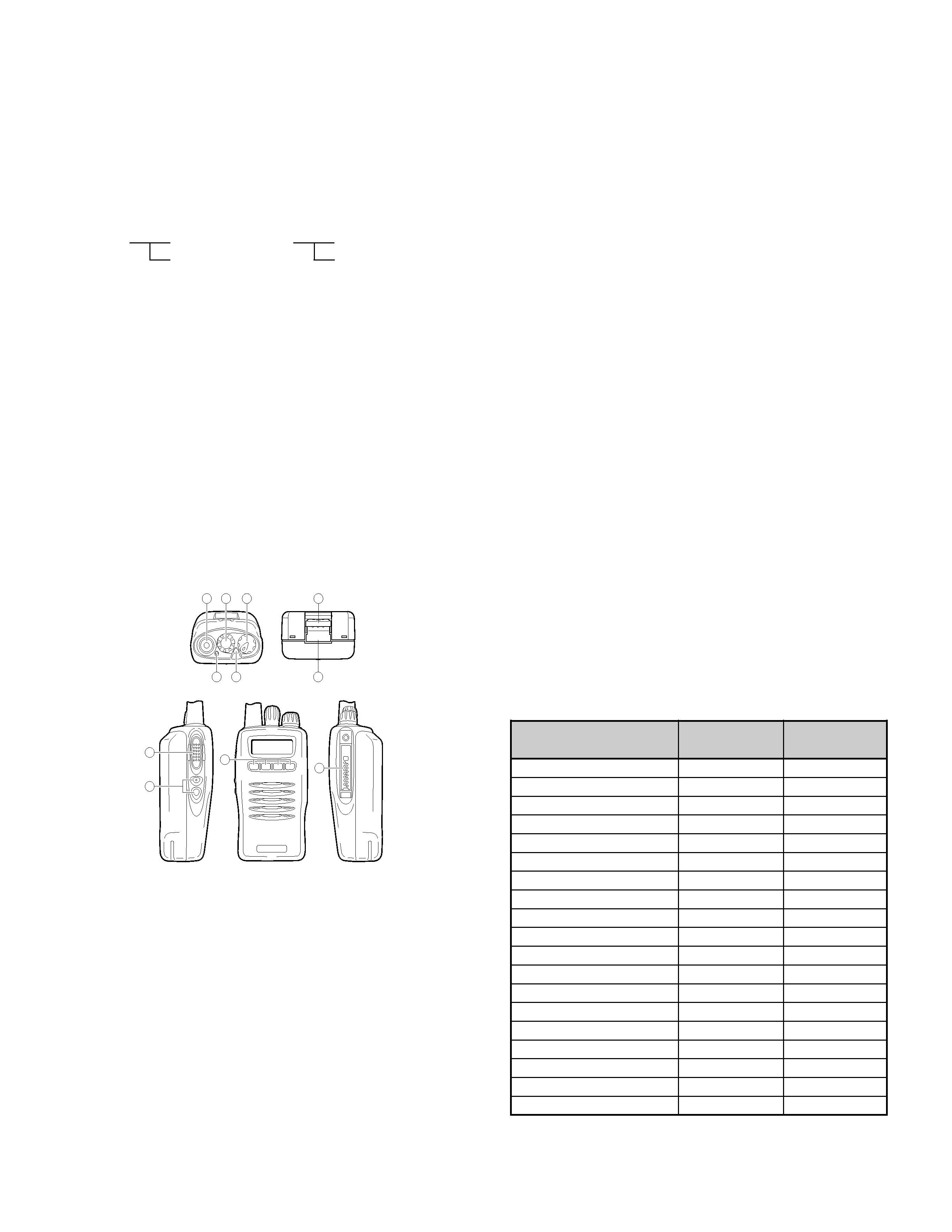
2-3. Display
1
These functions can be programmed only on key 2, the
encoder.
2
This function can be programmed only on key 5, the
Auxiliary (orange) key.
3
This function can be programmed only on key 9's A key.
4
This function can be programmed only on the programmable
function key of the optional KMC-25 speaker/ microphone.
1. Modes
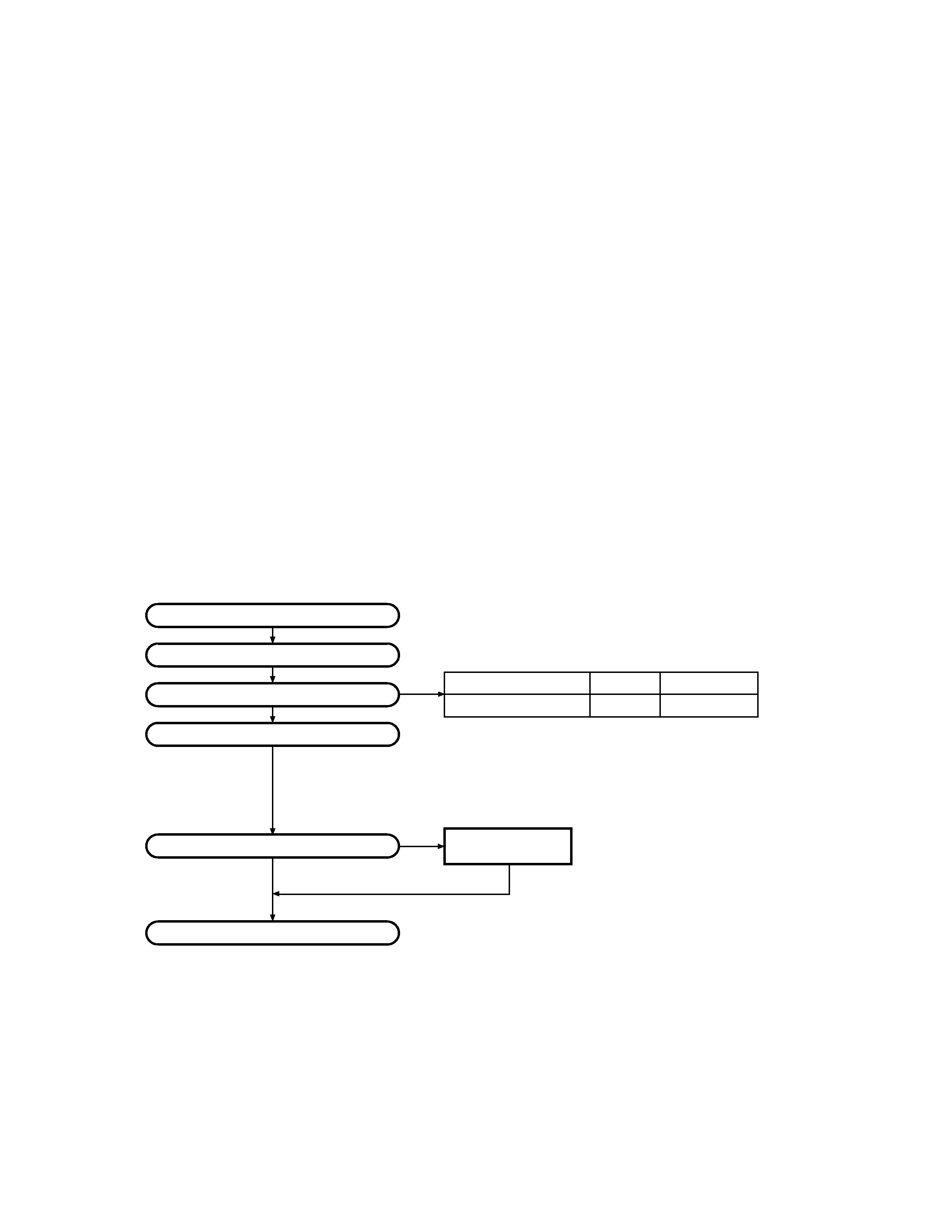
REALIGNMENT
Mode
Function
User mode
For normal use.
Panel test mode
Used by the dealer to check the
fundamental characteristics.
Panel tuning mode
Used by the dealer to tune the radio.
PC mode
Used for communication between the
radio and PC (IBM compatible).
Data program-
Used to read and write frequency data
ming mode
and other features to and from the radio.
PC test mode
Used to check the radio using the PC.
This feature is included in the FPU.
See panel tuning.
Firmware program-
Used when changing the main
ming mode
program of the flash memory.
Clone mode
Used to transfer programming data
from one radio to another.
Self programming
Frequency, signalling and features
mode (Conventional
write to the radio.
Format)
Firmware version
Firmware version number is displayed
information mode
on the LCD.
User mode
Panel test mode
PC mode
Firmware
programming mode
Clone mode
Self programming
mode (Conventional
Format)
Panel tuning mode
PC test mode
Data programming
mode
PC tuning mode
Firmware Version
Information mode
2. How to Enter Each Mode
Mode
Operation
User mode
Power ON
Panel test mode
[A]+Power ON (Two seconds)
PC mode
Received commands from PC
Panel tuning mode
[Panel test mode]+[S]
Firmware programming mode [S]+Power ON
Clone mode
[C]+Power ON (Two seconds)
Self programming mode
[LAMP]+Power ON
(Conventional Format)
(Two seconds)
Firmware version information [side 1] + Power ON
mode
(Two seconds)
3. Panel Test Mode
Setting method refer to ADJUSTMENT.
4. Panel Tuning Mode
Setting method refer to ADJUSTMENT.
TK-3140
5
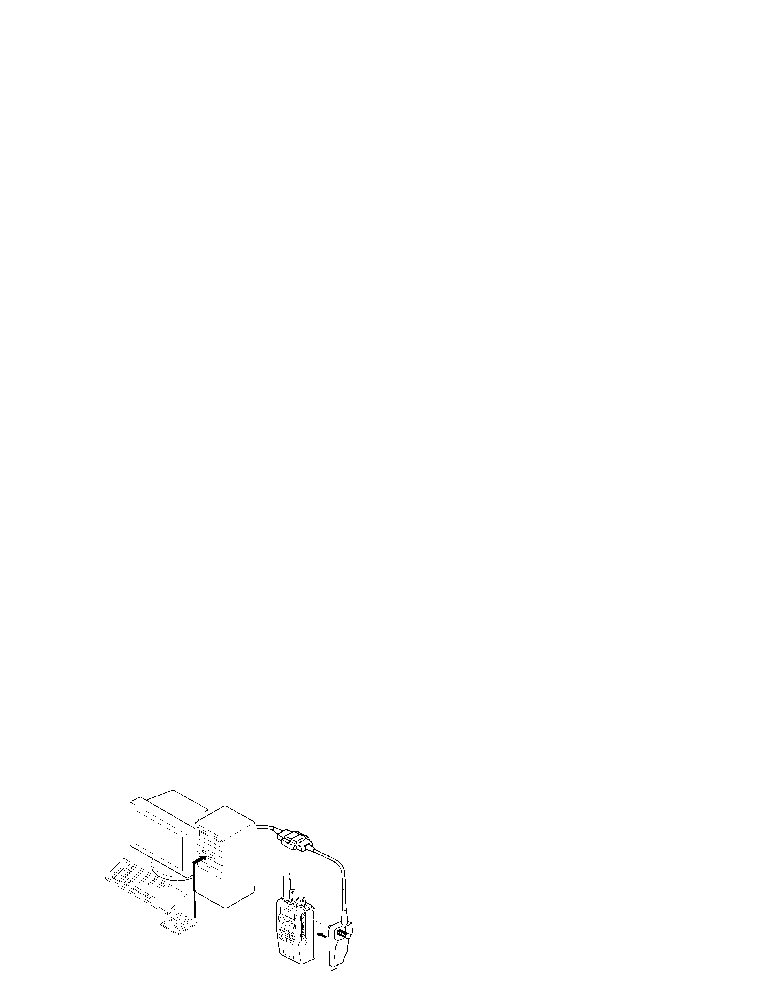
5.PC Mode
5-1. Preface
The TK-3140 transceiver is programmed by using a personal
computer, programming interface (KPG-36) and programming
software (KPG-74D).
The programming software can be used with an IBM PC or
compatible. Figure 1 shows the setup of an IBM PC for
programming.
5-2. Connection procedure
1. Connect the TK-3140 to the personal computer with the
interface cable.
2. When the POWER switch on, user mode can be entered
immediately. When PC sends command the radio enter PC
mode, and "PROGRAM" is displayed on the LCD.
When data transmitting from transceiver, the red LED is
blinking.
When data receiving to transceiver, the green LED is blinking.
Notes:
·
The data stored in the personal computer must match model
type, when it is written into the flash memory.
·
Change the TK-3140 to PC mode, then attach the interface
cable.
5-3. KPG-36 description
(PC programming interface cable: Option)
The KPG-36 is required to interface the TK-3140 to the
computer. It has a circuit in its D-subconnector (25-pin) case
that converts the RS-232C logic level to the TTL level.
The KPG-36 connects the universal connector of the TK-
3140 to the computers RS-232C serial port.
5-4. Programming software description
The KPG-74D programming disk is supplied in 3-1/2" disk
format. The software on this disk allows a user to program TK-
3140 radios via programming interface cable (KPG-36).
5-5. Programming with IBM PC
If data is transferred to the transceiver from an IBM PC with
the KPG-74D, the destination data (basic radio information)
for each set can be modified. Normally, it is not necessary to
modify the destination data because their values are
determined automatically when the frequency range (frequency
type) is set.
The values should be modified only if necessary. Data can
be programmed into the flash memory in RS-232C format via
the universal connector.
6. Firmware Programming Mode
6-1. Preface
Flash memory is mounted on the TK-3140. This allows the
TK-3140 to be upgraded when new features are released in
the future. (For details on how to obtain the firmware, contact
Customer Service.)
6-2. Connection procedure
Connect the TK-3140 to the personal computer (IBM PC or
compatible) with the interface cable (KPG-36). (Connection is
the same as in the PC Mode.)
6-3. Programming
1. Start up the programming software (Fpro.exe).
2. Set the communications speed (normally, 57600 bps) and
communications port in the comfiguration item.
3. Set the firmware to be updated by file name item.
4. Turn the TK-3140 power ON with the [S] switch held down.
When "PROG 57600" appears, release your finger from
the switch.
5. Check the connection between the TK-3140 and the
personal computer, and make sure that the TK-3140 Is in
the Program mode.
6. Press write button in the window. A window opens on the
display to indicate progress of writing. When the TK-3140
starts to receive data. the [P] icon is blinking.
7. If writing ends successfully, the LED on the TK-3140 lights
and the checksum is displayed.
9. If you want to continue programming other TK-3140 s,
repeat steps 4 to 7.
Notes:
q
This mode cannot be entered if the Firmware Programming
mode is set to Disable in the Programming software (KPG-
74D).
q
When programming the firmware, it is recommend to copy
the data from the floppy disk to your hard disk before update
the radio firmware.
Directry copying from the floppy disk to the radio may not
work because the access speed is too slow.
6-4. Function
1. If you press the [Side2] switch while "PROG 57600" is
displayed, the checksum is displayed. If you press the
[Side2] switch again while the checksum is displayed,
"PROG 57600" is redisplayed.
2. If you press the [Side1] switch while "PROG 57600" is
displayed, the display changes to "PROG 19200" to indicate
that the write speed is low speed (19200 bps). If you press
the [Side1] switch again while "PROG 19200" is displayed,
the display changes to "PROG 38400", and the write speed
becomes the middle-speed mode (38400 bps). If you press
the [Side1] switch again while "PROG 38400" is displayed,
the display returns to "PROG 57600".
Note:
Normally, write in the high-speed mode.
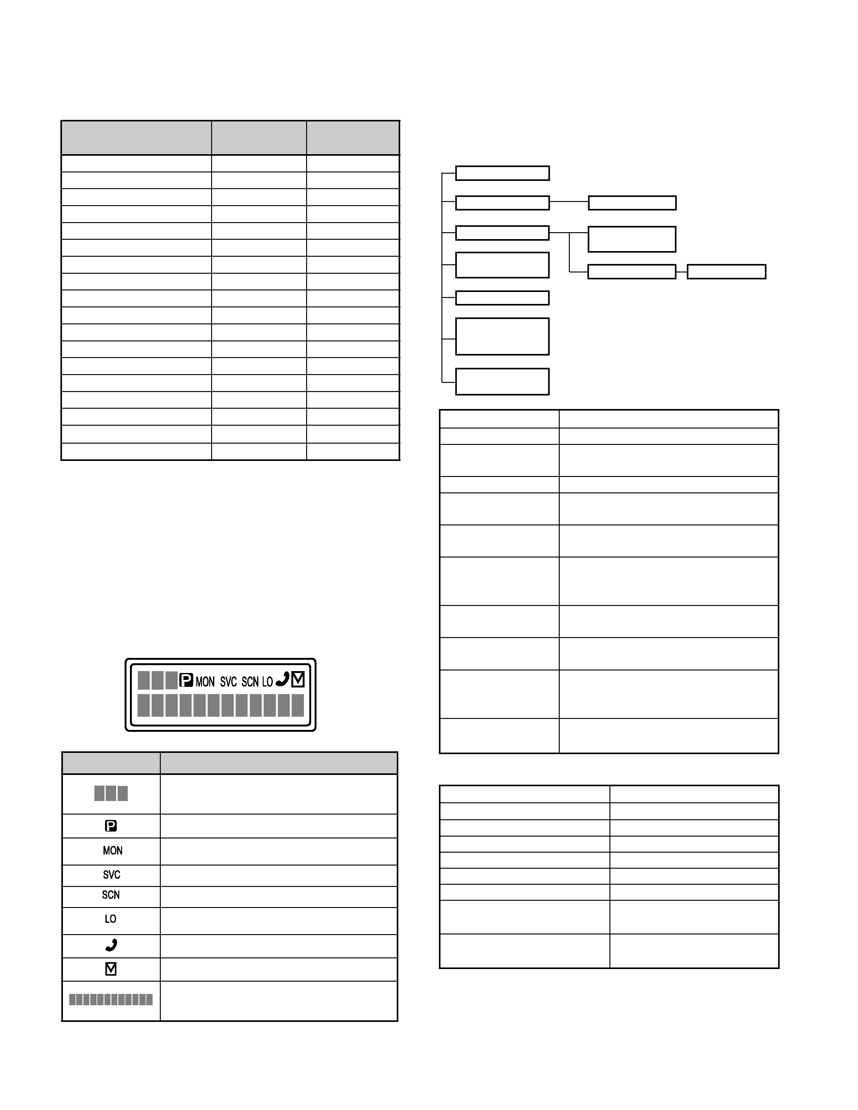
REALIGNMENT
KPG-36
IBM-PC
KPG-74D
Fig. 1