VHF FM TRANSCEIVER
TK-2202/2206
© 2004-2 PRINTED IN JAPAN
B51-8677-00 (S) 1246
SERVICE MANUAL
GENERAL ............................................................. 2
SYSTEM SET-UP ................................................. 2
REALIGNMENT .................................................... 3
DISASSEMBLY FOR REPAIR .............................. 5
CIRCUIT DESCRIPTION ....................................... 8
TERMINAL FUNCTION ...................................... 12
SEMICONDUCTOR DATA ................................. 12
COMPONENTS DESCRIPTION ......................... 13
PARTS LIST ........................................................ 14
EXPLODED VIEW ............................................... 20
PACKING ............................................................ 21
ADJUSTMENT ................................................... 23
PC BOARD
TX-RX UNIT (X57-6870-20) .......................... 28
SCHEMATIC DIAGRAM ..................................... 32
BLOCK DIAGRAM .............................................. 36
LEVEL DIAGRAM ............................................... 38
KSC-31 / KNB-29N / KNB-30A / KBH-10 ......... 39
SPECIFICATIONS ............................ BACK COVER
CONTENTS
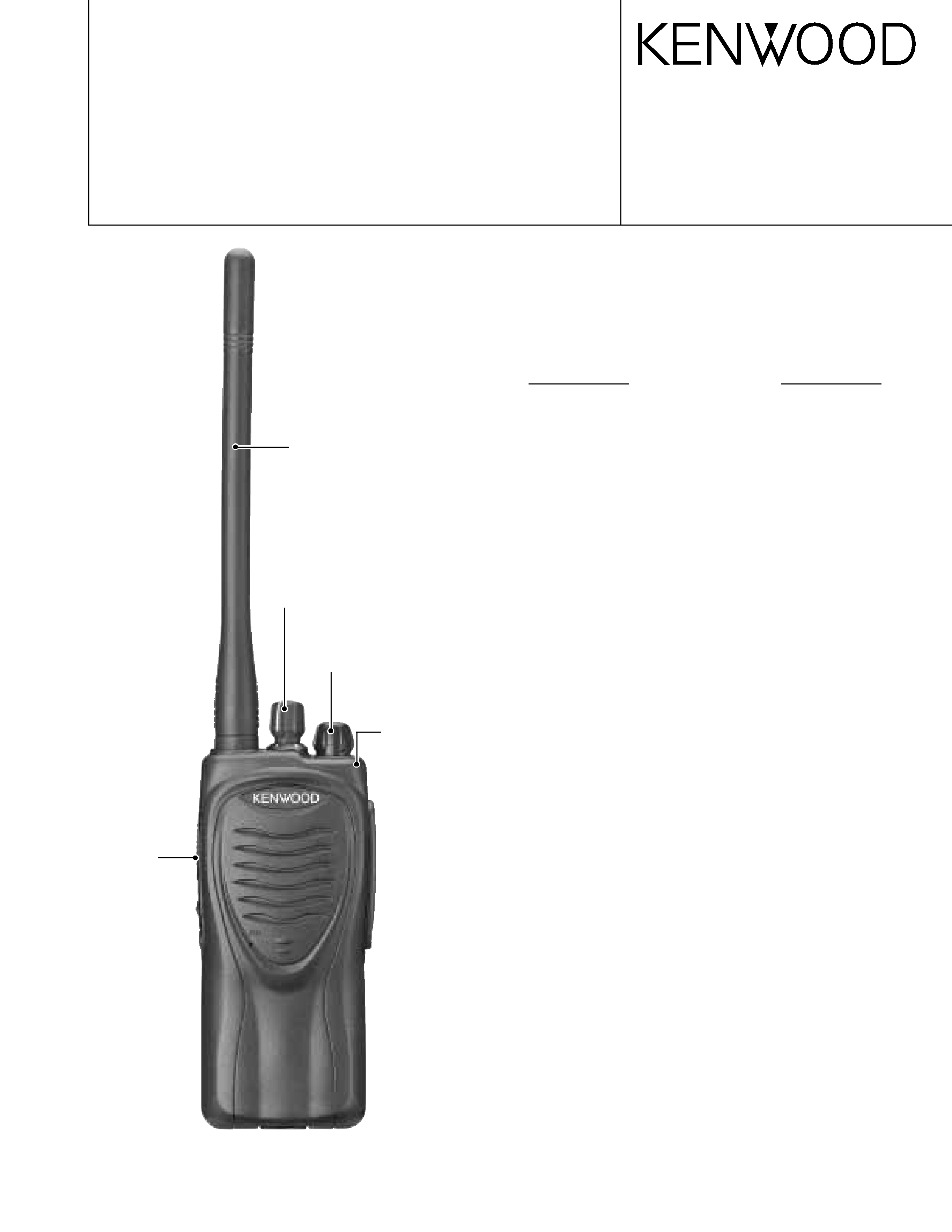
Antenna
(T90-1036-05): TK-2202(K,M)
(KRA-26: Option) TK-2206 (M)
Knob (VOLUME)
(K29-9309-03)
Knob (PTT)
(K29-9308-03)
Cabinet assy
(A02-3852-23)(8CH):
TK-2202(K,M)
(A02-3851-23)(16CH):
TK-2206(M)
Knob (CH-SELECTOR)
(K29-9318-03)
TK-2206 :
Does not come with antenna.
Antenna is available as an option.
Photo is TK-2202.
TK-2202/2206
2
GENERAL / SYSTEM SET-UP
SYSTEM SET-UP
Merchandise received
License and frequency allocated by FCC
Choose the type of transceiver
Transceiver programming
Delivery
Are you using the speaker microphone?
A personal computer (IBM PC or compatible), programming
interface (KPG-22), and programming software (KPG-87D)
are required for programming.
(The frequency, TX power HI/LOW, and signalling data are programmed
for the transceiver.)
YES
NO
KMC-17 or KMC-21
Speaker microphone
(Option)
Are you using the optional antenna?
YES
NO
KRA-22 or KRA-26
Optional antenna
TX/RX 136~174
5.0W
TK-2202 (K,M)
TK-2206 (M)
Frequency range (MHz) RF power
Type
Unit
Model
TX-RX Unit
Frequency range
Remarks
& destination
TK-2202 K,M
X57-6870-20
136~174MHz
IF1 : 38.85MHz
TK-2206
M
LOC : 38.4MHz
INTRODUCTION
SCOPE OF THIS MANUAL
This manual is intended for use by experienced technicians
familiar with similar types of commercial grade communications
equipment. It contains all required service information for the
equipment and is current as of the publication date. Changes
which may occur after publication are covered by either Service
Bulletins or Manual Revisions. These are issued as required.
ORDERING REPLACEMENT PARTS
When ordering replacement parts or equipment information,
the full part identification number should be included. This
applies to all parts, components, kits, or chassis. If the part
number is not known, include the chassis or kit number of
which it is a part, and a sufficient description of the required
component for proper identification.
PERSONAL SAFETY
The following precautions are recommended for personal
safety:
DO NOT transmit until all RF connectors are verified secure
and any open connectors are properly terminated.
SHUT OFF and DO NOT operate this equipment near
electrical blasting caps or in an explosive atmosphere.
This equipment should be serviced by a qualified technician
only.
SERVICE
This radio is designed for easy servicing. Refer to the
schematic diagrams, printed circuit board views, and alignment
procedures contained within.
TK-2202/2206
3
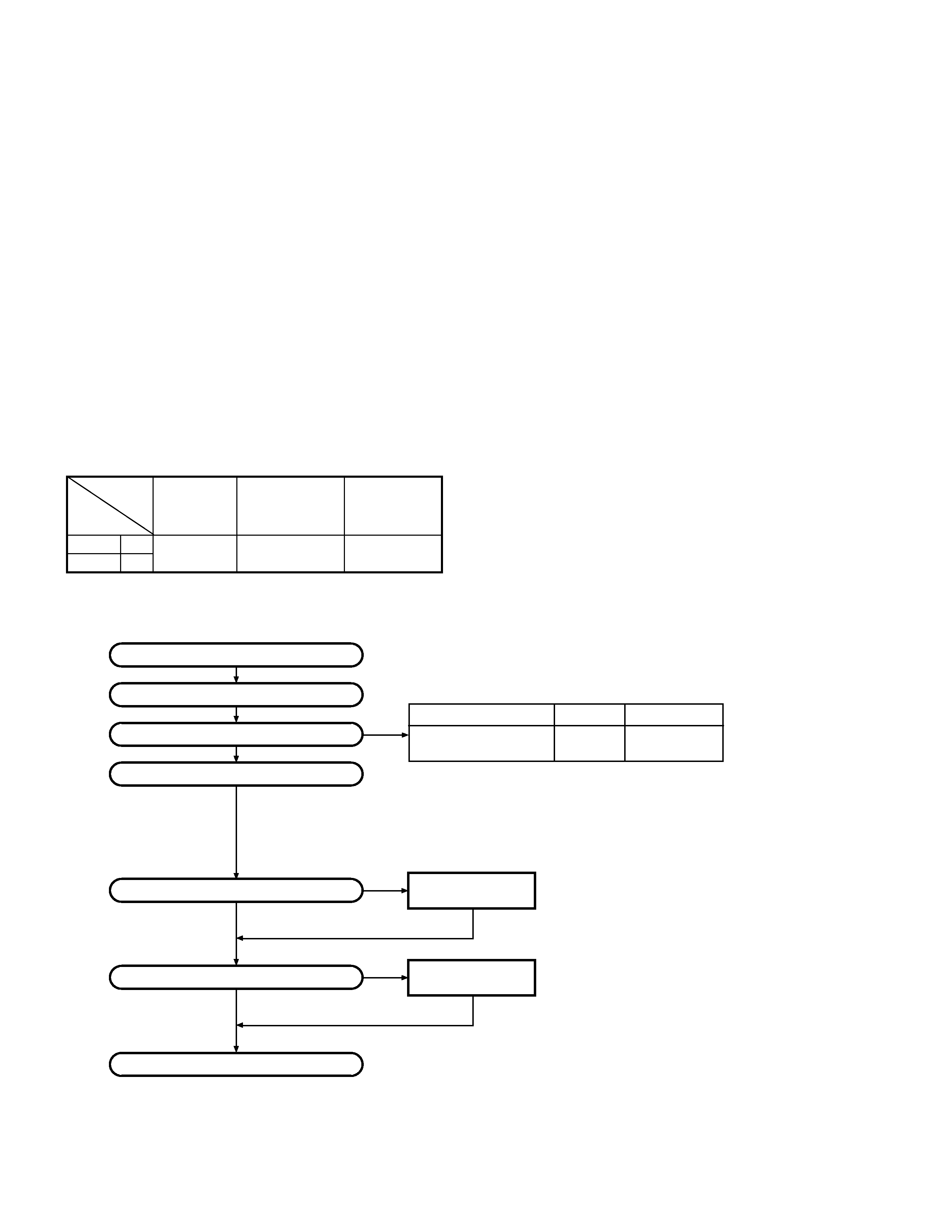
2. How to Enter Each Mode
Mode
Operation
User mode
Power ON
PC mode
Received commands from PC
Clone mode
[PTT]+[Side2]+Power ON (Two seconds)
Mode
Function
User mode
For normal use.
PC mode
Used for communication between the
radio and PC (IBM compatible).
Data programming
Used to read and write frequency data
mode
and other features to and from the radio.
PC test mode
Used to check the radio using the PC.
This feature is included in the KPG-
87D.
Clone mode
Used to transfer programming data
from one radio to another.
REALIGNMENT
1. Modes
User mode
PC mode
PC test mode
Data programming
mode
PC tuning mode
REALIGNMENT
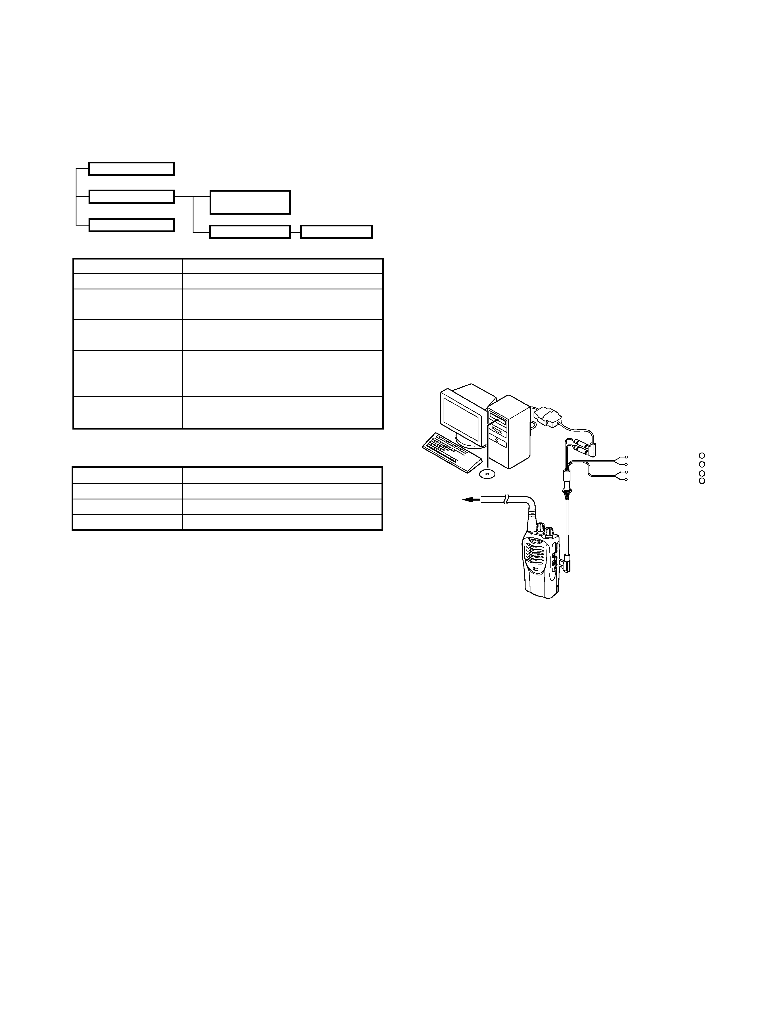
3. PC Mode
3-1. Preface
The TK-2202/2206 transceivers are programmed using a
personal computer, a programming interface (KPG-22) and
programming software (KPG-87D).
The programming software can be used with an IBM PC
or compatible. Figure 1 shows the setup of an IBM PC for
programming.
3-2. Connection procedure
1. Connect the TK-2202/2206 to the personal computer with
the interface cable.
2. When the POWER is switched on, user mode can be
entered immediately. When the PC sends a command,
the radio enters PC mode.
When data is transmitting from the transceiver, the red
LED lights.
When data is received by the transceiver, the green LED
lights.
Notes:
·
The data stored in the personal computer must match the
model type when it is written into the EEPROM.
·
Change the TK-2202/2206 to PC mode, then attach the
interface cable.
3-3. KPG-22 description
(PC programming interface cable: Option)
The KPG-22 is required to interface the TK-2202/2206 with
the computer. It has a circuit in its D-subconnector (25-pin)
case that converts the RS-232C logic level to the TTL level.
The KPG-22 connects the SP/MIC connector of the TK-2202/
2206 to the computer's RS-232C serial port.
3-4. Programming software description
KPG-87D is the programming software for TK-2202/2206
supplied on a CD-ROM. This software runs under Windows
98, ME, Windows 2000 or XP on an IBM-PC or compatible
machine.
The data can be input to or read from TK-2202/2206 and
edited on the screen. The programmed or edited data can be
printed out. It is also possible to tune the transceiver.
Tuning cable
(E30-3216-05)
RF Power meter
or SSG
Gray
+
Gray/Black
1.5D-XV Lead wire
+
1.5D-XV Shield wire
}
}
SP
MIC
KPG-22
KPG-87D
IBM-PC
Fig. 1
Clone mode
4. Clone Mode
4-1. Outline
"Clone Mode" copies the transceiver data to another
transceiver.
The dealer can copy the transceiver data to another
transceiver even without the use of a personal computer.
4-2. Example
The transceiver can copy the programming data to one or
more transceivers via RF communication.
The clone master and clone slave/s must be in Clone mode.
4-3. Operation
1. To switch the clone slave/s to Clone mode, press and hold
the [PTT] and [side2] keys while turning the transceiver
power ON.
2. Wait for 2 seconds. The LED will light orange and the
transceiver will announce "Clone".
3. Select a channel table number using Side1(increment
channel table) and Side2(decrement channnel table) keys.
TK-2202/2206
4
Clone Frequency Table
Operating Frequency
Clone
(MHz)
136~174
Frequency Table
4. To switch the clone master to Clone mode, press and hold
the [PTT] and [side2] keys while turning the transceiver
power ON.
5. Wait for 2 seconds. The LED will light orange and the
transceiver will announce "Clone".
6. Select the same channel table number as the clone slave/s.
7. Press [PTT] on the clone master to begin data transmission.
When the clone slave starts to receive data, the LED will
light green.
When the clone master finishes sending data, a
"confirmation" tone will sound.
If data transmission fails while cloning, an "error" tone will
sound from the Slave unit.
8. If the cloning fails, no data will be available in the Slave unit
when it is returned to User mode.
9. When the cloning is successful, the Slave unit's "Scan" and
"Key lock" functions will return to their default values (Scan
= OFF, Key lock = OFF).
Notes:
·
The dealer can clone data to two or more transceivers by
repeating the above procedures.
·
If the transceivers Clone Mode is configured as "Disabled",
the transceiver cannot enter Clone mode.
·
The table shown below will cover the frequency tables used
for wireless cloning.
·Clone mode cannot be entered in battery low state.
·A unit cannot be a "Master Unit" if it is unprogrammed. If
[PTT] is pressed, an "error" tone will sound.
·
The language used in cloning depends on the "Model type"
setting, not the FPU setting. C, C2, C5 and C6 type
TK-3207 transceivers will use Chinese. Other types English.
·
Once a unit is set to be the Master, it cannot be a slave
after the data has been transmitted. This protects the data
in the Master unit.
·
Electronic interface may cause a failure in data transfer
during Wireless Clone, such as when waveforms or
electromagnetics are being performed at the workbench.
·
Clone mode can be used ONLY by the authorized service
personnel.
·
The Clone mode setting must be configured as "Disable"
before being delivered to the end-user.
·
To clone, replace the antenna from both the master
transceiver and the slave transceiver with a dummy
load.
·
The transmit output power is automatically set to Low
in Clone mode.
REALIGNMENT
1
136.000
2
138.000
3
140.000
4
142.000
5
144.000
6
146.000
7
148.000
8
150.000
9
152.000
10
154.000
11
156.000
12
158.000
13
160.000
14
162.000
15
164.000
16
166.000
17
168.000
18
170.000
19
172.000
20
174.000
TK-2202/2206
5
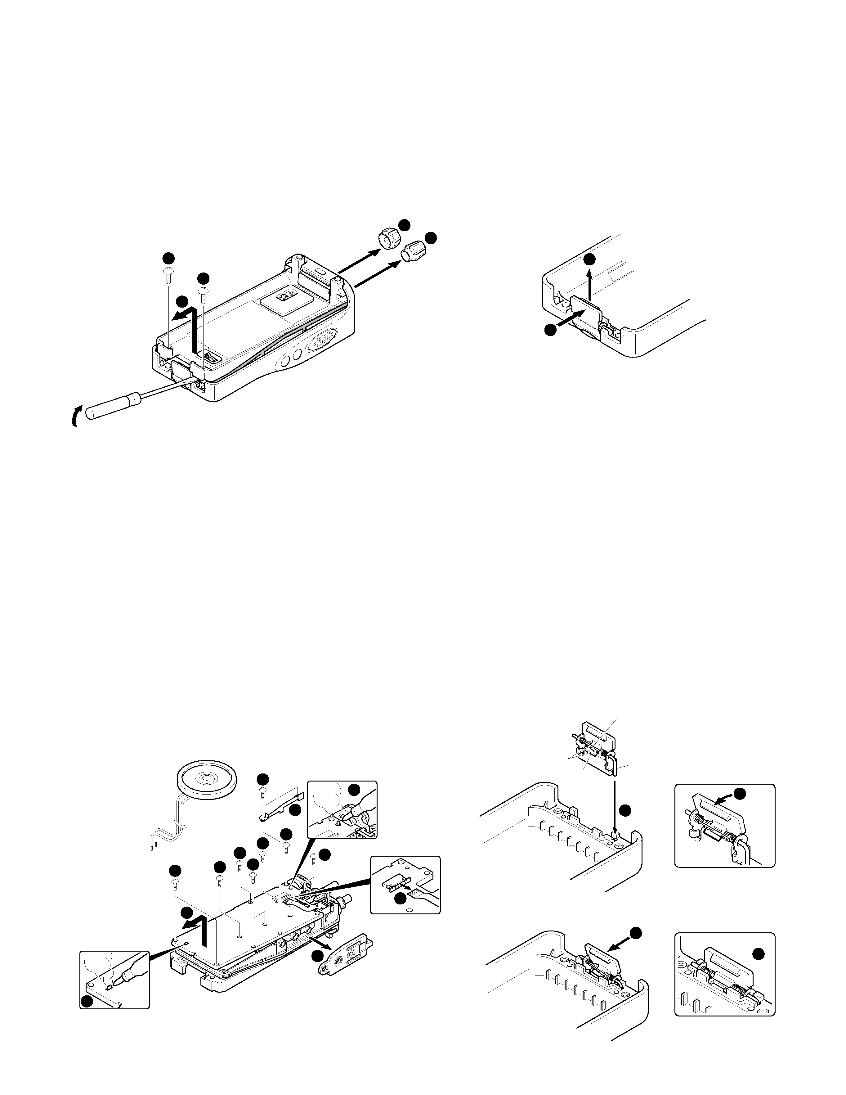
DISASSEMBLY FOR REPAIR
Removing the case assembly from the chassis.
1. Remove the volume knob
z and channel knob x.
2. Remove the two screws
c.
3. Lift and remove the chassis from the case assembly
v.
(Use a flat-blade screwdriver to easily lift the chassis.)
Removing the TX-RX unit from the chassis.
1. Remove the packing
b from the SP / MIC jack of the TX-
RX unit.
2. Remove the eleven screws
n fixing the TX-RX unit.
3. Remove the fixing bracket
m of the SP / MIC.
4. Remove the solder of the antenna terminal with a soldering
iron
,.
5. Remove the solder of the positive terminal with a soldering
iron
..
Note: You can remove the TX-RX unit from the chassis without
removing the solder at the positive terminal. However,
in this case, you can not attach the packing (G53-1605-
03) that is on the positive terminal to the chassis in
assembling. So, it is advisable to remove the solder on
the positive terminal first.
6. Remove the FPC from the flat cable connector /.
7. Lift and remove the TX-RX unit from the chassis .
1
3
3
4
2
9
6
6
6
6
6
11
5
6
6
6
7
8
10
Removing the battery release lever from the case
assembly.
1. Press the upper part of the lever toward the inside of the
case assembly. One side of the shaft will be removed
z.
2. Lift and remove the battery release lever from the case
assembly
x.
Attaching the battery release lever to the case
assembly.
1. Insert one side of the shaft into the hole at the lever fitting
section on the case assembly
z.
Caution : The thin spring (G01-4543-04) should be positioned
above the two tabs of the lever.
2. Tilt the battery release lever slightly forward
x, so that the
thick spring (G01-4542-04) is positioned below the case
surface.
3. With the thick spring positioned below the case surface,
attach the other side of the shaft to the case assembly by
pressing the battery release lever
c until it snaps into place
v.
Caution : Be careful not to tilt the battery release lever too
forward.
If the battery release lever is pushed in this state
where the two tabs come below the case surface,
there is a possibility of damaging the two tabs.
2
1
1
3
2
4
A thin spring
Shaft
Two tabs
A thick spring