© 2001-8 PRINTED IN JAPAN
B51-8575-00 (S) 668
VHF FM TRANSCEIVER / VHF FM
TK-2118
SERVICE MANUAL /
GENERAL .................................................................. 2
REALIGNMENT ......................................................... 3
CIRCUIT DESCRIPTION ......................................... 11
SEMICONDUCTOR DATA ....................................... 17
DESCRIPTION OF COMPONENTS ........................ 19
TERMINAL FUNCTION ........................................... 21
PARTS LIST ............................................................. 22
EXPLODED VIEW ................................................... 29
PACKING ................................................................. 30
ADJUSTMENT ......................................................... 31
PC BOARD VIEWS
DISPLAY UNIT (X41-3583-00) ............................ 37
TX-RX UNIT (X57-6233-00) ................................ 39
SCHEMATIC DIAGRAM .......................................... 51
BLOCK DIAGRAM .................................................. 55
LEVEL DIAGRAM ................................................... 57
BC-20, PB-40, PB-41, BT-12 ................................... 58
SPECIFICATIONS ................................ BACK COVER
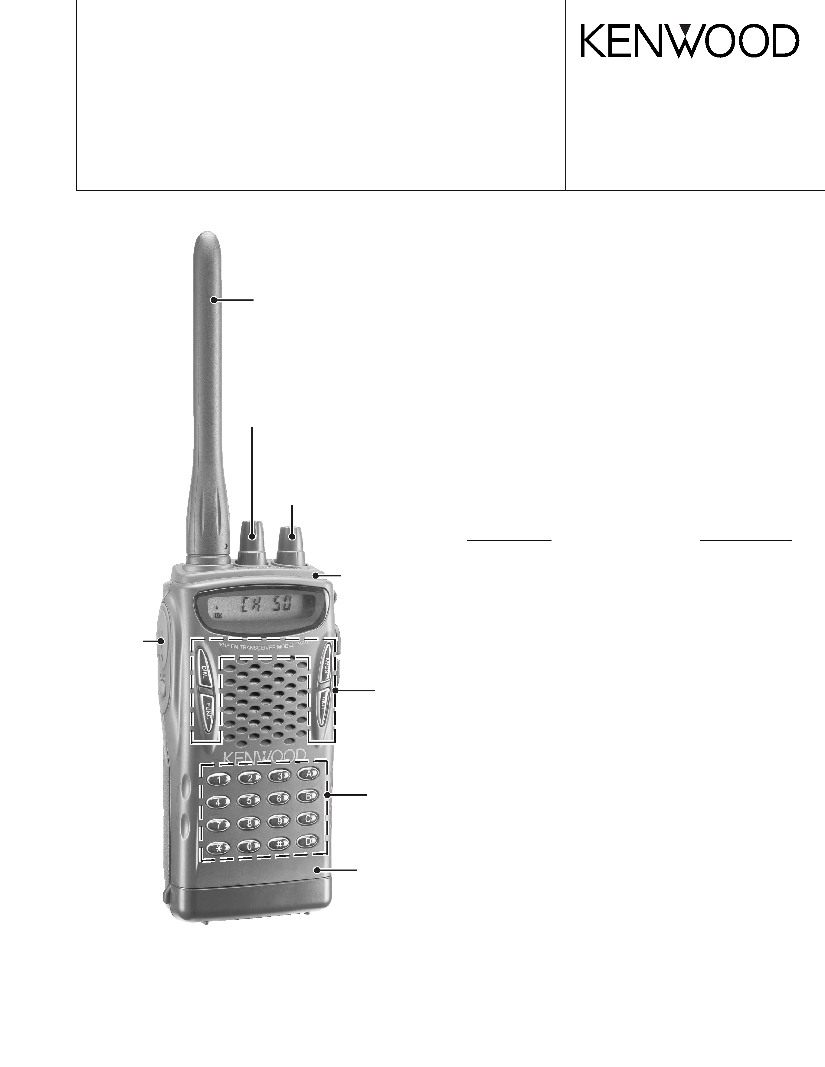
Helical Antenna
(T90-0757-05)
Knob(ENC)
(K29-5443-03)
TK-2118
CONTENTS
Knob
(VOL)
(K29-5442-03)
Key top
(DIAL, SCAN)
(K29-9026-13)
Knob
(PTT, MONI)
(K29-9027-03)
Cabinet assy
(Front)
(A02-3512-13)
Key top(DTMF)
(K29-9028-13)
Panel assy
(A62-0932-03)

2
TK-2118
TK-260
:K, K2
INTRODUCTION
SCOPE OF THIS MANUAL
This manual is intended for use by experienced technicians
familiar with similar types of commercial grade
communications equipment. It contains all required service
information for the equipment and is current as of the
publication date. Changes which may occur after publication
are covered by either Service Bulletins or Manual Revisions.
These are issued as required.
ORDERING REPLACEMENT PARTS
When ordering replacement parts or equipment
information, the full part identification number should be
included. This applies to all parts : components, kits, or
chassis. If the part number is not known, include the chassis or
kit number of which it is a part, and a sufficient description of
the required component for proper identification.
PERSONAL SAFETY
The following precautions are recommended for personal
safety :
· DO NOT transmit until all RF connectors are verified secure
and any open connectors are properly terminated.
· SHUT OFF and DO NOT operate this equipment near
electrical blasting caps or in an explosive atmosphere.
· This equipment should be serviced by a qualified
technician only.
SERVICE
This radio is designed for easy servicing. Refer to the
schematic diagrams, printed circuit board views, and
alignment procedures contained within.
Destnation
Number of CH
RF power output
C50
5W/2W
C50
5W/2W
GENERAL /
. ............................................................................ 2
...................................................................... 3
.................................................................... 11
................................................................18
.................................................................... 19
.................................................................... 21
....................................................................... 22
................................................................29
........................................................................... 30
........................................................................... 31
PC
(X41-3583-00) ....................................... 37
(X57-6233-00) ............................. 39
....................................................................... 51
....................................................................... 55
....................................................................... 57
BC20, PB40, PB41, BT-12 ............................... 58
........................................................................
·
·
·
3
TK-2118
TK-260
:K, K2
REALIGNMENT/
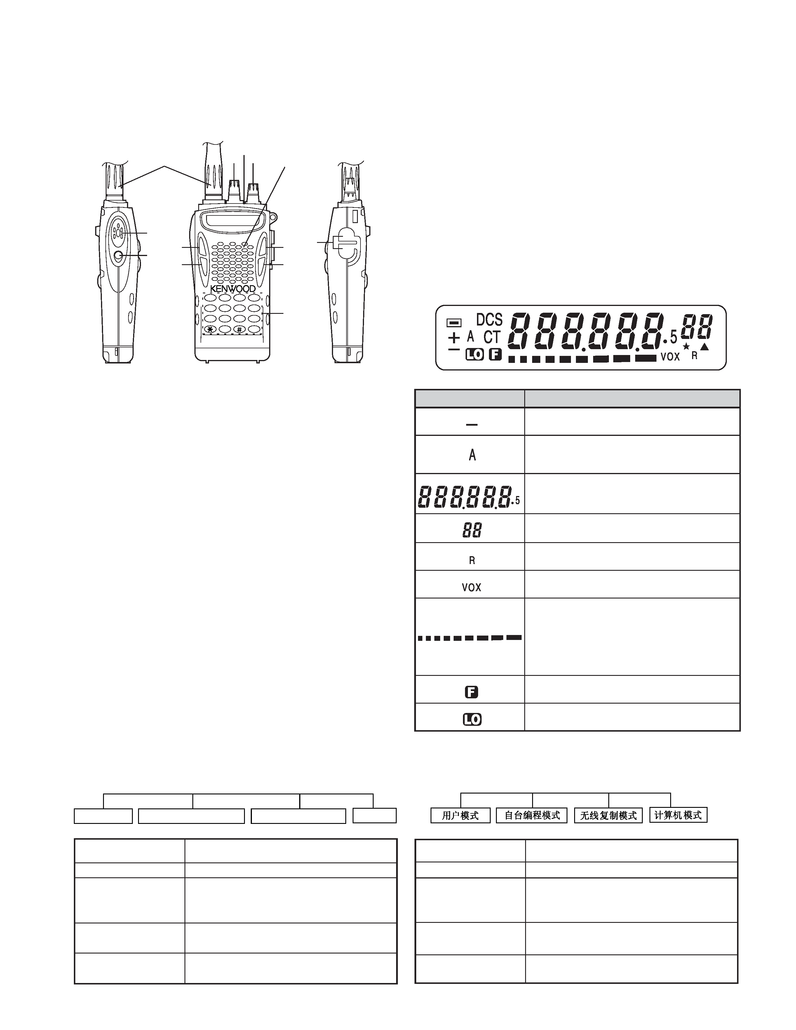
MODE
FUNCTION
User Mode
For normal use.
Self Programming
You can Program the RF frequency,
Mode
QT/DQT and other functions using only
the radio.
Wireless Clone Mode Used to transfer programming data
from one radio to another.
PC Mode
Used for communication between the
radio and a PC
2. Modes
Self Programming Mode
User Mode
Wireless Clone Mode
PC Mode
2.
QT/DQT
q
q
q
q
q
PowerVolume
w
w
w
w
w
LED
DTMF
e
e
e
e
e
r
r
r
r
r
PTT
t
t
t
t
t
MONI
FUNC QT
y
y
y
y
y
DIAL
DTMF FUNC
u
u
u
u
u
FUNC
i
i
i
i
i
SCAN
FUNC
q e
w
r
t
u
y
o
i
!0
!1
12
3
A
45
6
B
78
9
C
0
D
D
IA
L
LO
W
SCAN
F
U
N
C
VHF FM TRANSCEIVER MODELTK-2118
PTT
MONI
MIC
S
P
-
1.
o
o
o
o
o
LOW
FUNC
VOX
!0
!0
!0
!0
!0
DTMF
DTMF
!1
!1
!1
!1
!1
MIC-SP
VOX
FUNC
4
TK-2118
TK-260
:K, K2
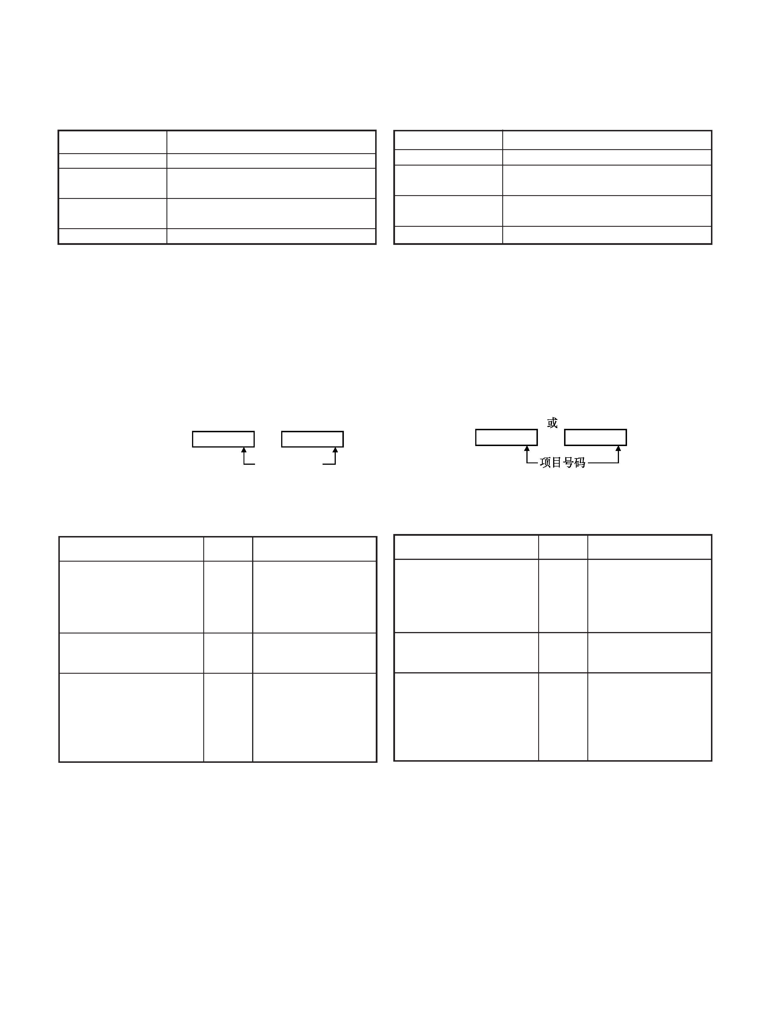
3. How to enter each mode
MODE
PROCEDURE
User Mode
Power ON
Self Programming
[MONI] + [DIAL] + POWER ON
Mode
(More than 2 sec)
Wireless Clone mode [MONI] + [LOW] + POWER ON
(More than 2 sec)
PC Mode
received commands from PC
4. Self Programming mode
After entering self-programming Mode, the radio allows 3
types of operation:
Function setting / Channel setting / All Reset
When self-programming is disable through using the FPU, self
programming mode cannot be turned ON.
1) Function setting
You can program 3 settings.
Operation:
After entering Self-Programming Mode Press the [SCAN] key.
The LCD changes to
If your radio is programmed with the selective call function,
the LCD changes to (1).
When you press the PTT switch after setting the data, you
continue to the next item. (Refer to page 7 item 5)
Selecting the setting items
Display
Setting contents
(Example)
You can enter 3 digit code
(000 to 999) using the DTMF
keys.
This feature is available only
when "Selective Call" has
been activated in the radio.
OFF: No, ON: Yes
This item is selected using
the channel selector.
Setting the Selective Call
Code
(3 Digit)
Setting the BEEP ON or OFF
Setting the [MONI] Key
Assignment
(
000 0 )
(
ON 1 )
(
0 2 ) 0: Squelch OFF,
1: Monitor Toggle,
2: Monitor Momentary,
OFF: OFF
You can select from
among the above settings.
This item is selected using
the channel selector.
3.
ON
[MONI][DIAL]ON (2)
[MONI][LOW]ON (2)
REALIGNMENT/
4.
//
FPU
1)
[SCAN]
LCD
LCD (1)
PTT
75
()
DTMF3
000-999
"
"
OFF: , ON:
(3)
ONOFF
[MONI]
(
000 0 )
(
ON 1 )
(
0 2 ) 0:
1: ,
2: ,
OFF:
000 0
ON 1
Item number
(1)
(2)
or
000 0
ON 1
(1)
(2)
5
TK-2118
TK-260
:K, K2
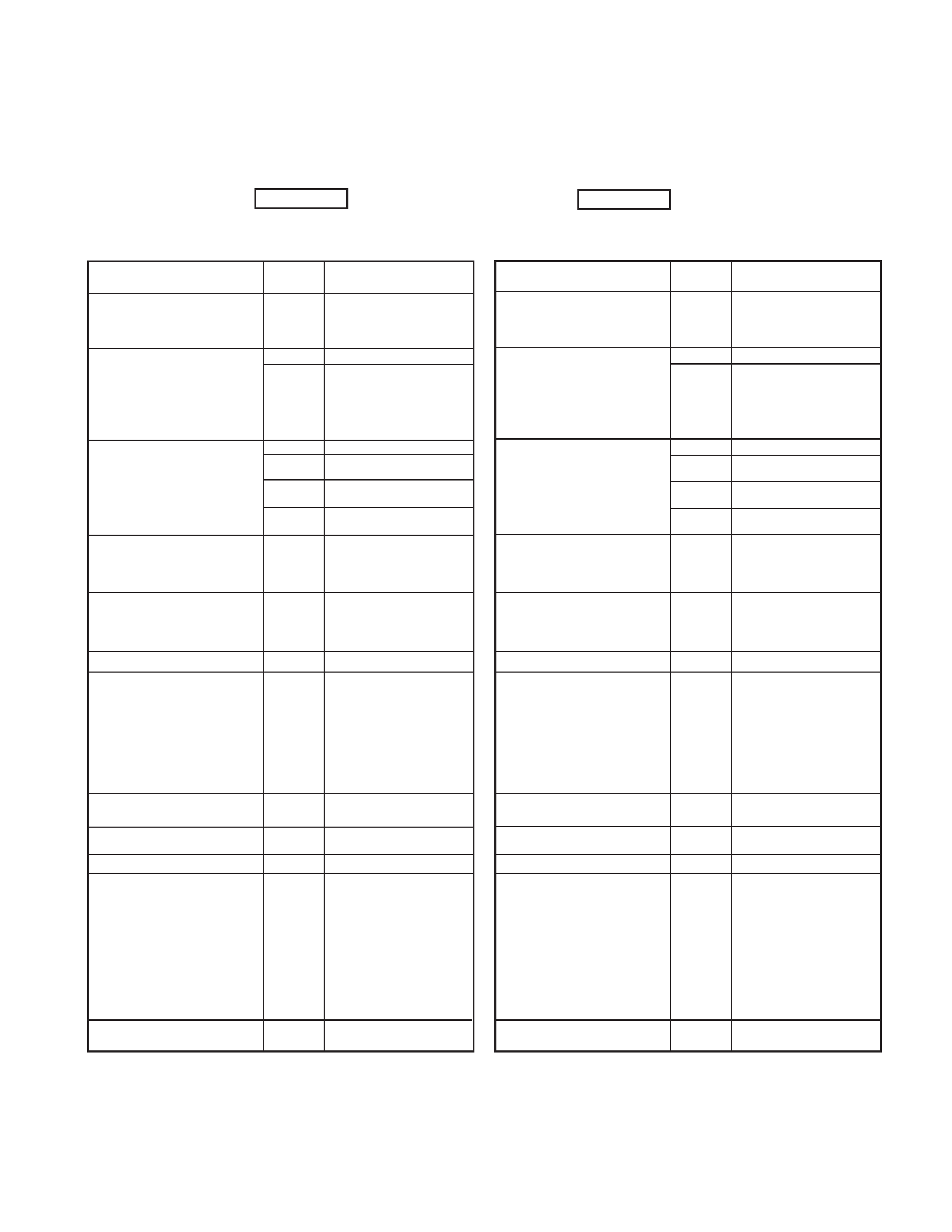
2) Channel setting
Operation:
After entering Self-Programming Mode Press the [LOW] key.
The LCD changes to
CH
1
1
When you press the PTT switch after setting the data, you
can continue to the next Item. (Refer to page8 item 6)
...
REALIGNMENT/
2)
[LOW]
LCD
CH
1
1
PTT
86
()
1-50
(
CH 1 1 )
Selecting the setting items
Display
Setting contents
(Example)
Channel range from 1 to
50.
Setting the channel number
When a channel number is not
set, the following items will not
be selected.
(
CH 1 1 )
Blank
100.00000MHz~549.99500MHz
(VHF: 5kHz(Default) /
6.25kHz Step)1
Default (C): 150.000MHz
(C2): 140.000MHz
Setting the receive QT/DQT
When a channel number is not set,
this item will be skipped.
(
......
2 )
(
OFF 3 ) OFF
QT(QT frequencies
table)2: 67.0Hz ~ 250.3Hz
DQT(DQT Normal/Inverse table)
2: 023 ~ 754 Normal setting
DQT(DQT Normal/Inverse table)
2: -023 ~ -754 Inverse setting
Setting the receive frequency
When a receive frequency is not
set ("blank" is set), the following
items will not be selected. (Item
numbers 3 to 12 are not selected.)
When "blank" is set, you will return
to "setting the channel number".
Setting the transmit frequency Same as
RX Display
(This is item
number "4".)
Same content as "Setting
the received frequency"
Setting the transmit QT/DQT
When a transmit frequency is not
set, this item will be skipped.
Same as
RX Display
(This is item
number "5".)
Same content as
"Setting the receive QT/
DQT"
(
150.000 2 )
(
q 100.0 3 )
(
d 023 3 )
(
d -023 3 )
Setting the option signalling
0: None
1: DTMF
Setting the BUSY CH Lockout
(BCL)
OFF: OFF 1: Carrier
2: QT/DQT 3: DTMF
For
setting
number
"3"(DTMF), if of Option
Signaling is changed from
"DTMF" to "None" before the
BCL setting is entered, the
BCL setting contents will be
automatically set to "OFF"
(OFF).
Setting the Beat Shift
function ON or /OFF
OFF: No
ON: Yes
Setting Scan DELETE / ADD
del: Scan DELETE
Add: Scan ADD
Setting Wide / Narrow
0: Narrow
1: Wide
Setting the SP Unmute
When option signaling is set
to "0" (None), this item will be
skipped.
0: Carrier or QT/DQT
1: Carrier + DTMF or QT/
DQT + DTMF
For setting number "1"
(Carrier + DTMF or QT/DQT +
DTMF), if Option Signaling is
changed from "DTMF" to
"None" before the SP Unmute
setting item is entered, the SP
Unmute setting contents will
be automatically set to "0"
(Carrier or QT/DQT).
Setting the transmit power
H: High power
L: Low power
(
0
6 )
(
OFF 7 )
(
OFF 8 )
(
Add 9 )
(
0 10 )
(
0 11 )
(
H 12 )
1 Step change for setting the frequency
MHz step: Routed the Channel selector while pressing the
[1] key.
5kHz or 6.25kHz step: Press the [SCAN] key
(
"")
(3-12)
""
""
(......
2 )
(
150.000 2 )
100.00000MHz~549.99500MHz
(VHF: 5kHz() /6.25kHz
Step)*1
(C): 150.000MHz
(C2): 140.000MHz
QT/DQT
(
OFF 3 ) OFF
QT(QT )*2:
67.0Hz ~ 250.3Hz
DQT(DQT /)*2:
023 ~ 754
DQT(DQT /)*2:
-023 ~ -754
(
q 100.0 3 )
(
d 023
3 )
(
d -023
3 )
(
"4".)
""
QT/DQT
(
"5".)
" QT/DQT"
0:
1: DTMF
(BCL)
OFF:
1:
2: QT/DQT 3: DTMF
"3" (DTMF)
BCL
"DTMF"
" " B C L
"OFF"
()
ONOFF
OFF:
ON:
del:
Add:
0:
1:
SP
"0" ()
0: QT/DQT
1: + DTMF
QT/DQT + DTMF
"1"(+
DTMFQT/DQT+DTMF)
S P
"DTMF" ""SP
"0" (QT/ DQT)
H:
L:
(
0
6 )
(
OFF
7 )
(
OFF 8 )
(
Add 9 )
(
0 10 )
(
0 11 )
(
H 12 )
1
MHz[1]
5kHz6.25kHz: [SCAN]