70%
COMPACT AUDIO SYSTEM
RD-M23
SERVICE MANUAL
(For E,T, type)
© 2001-6 PRINTED IN KOREA
B51-5732-00 (K/K) 1847
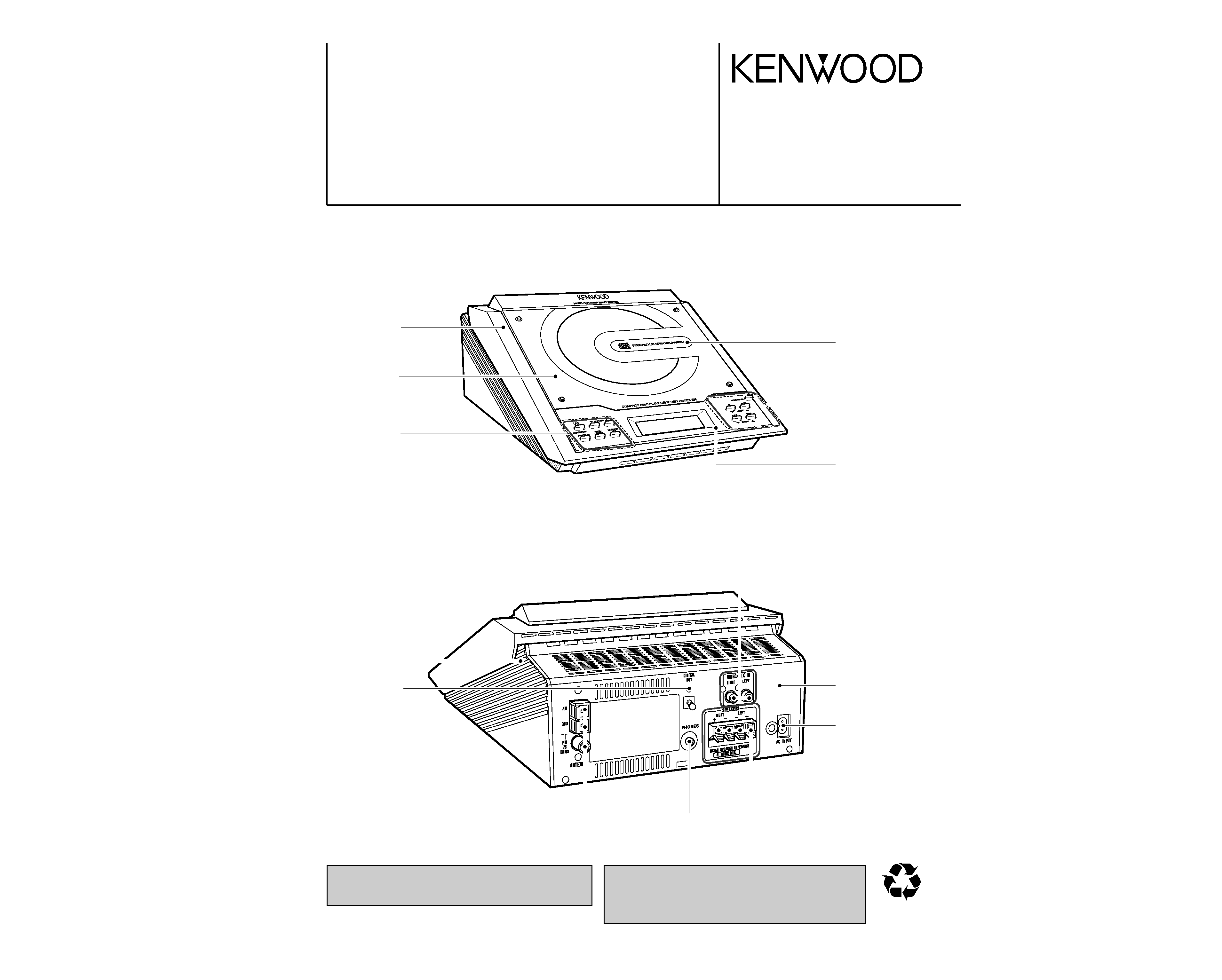
Front cabinet
(A60-2147-08)
Knob
(K29-8085-08)
Clear panel(DISK)
(B10-3764-08)
In compliance with Federal Regulations, following are repro-
duction of labels on, or inside the product relating to laser prod-
uct safety.
KENWOOD-Crop. certifies this equipment conforms to DHHS
Regulations No.21 CFR 1040. 10, Chapter 1, subchapter J.
DANGER : Laser radiation when open and interlock defeated.
AVOID DIRECT EXPOSURE TO BEAM.
Plate
(B03-3900-08)
CD lid
(J19-6268-08)
Knob
(K29-8084-08)
Rear panel
(A80-4145-08)
Digital out jack
(W02-2878-08)
Bottom cabinet
(A10-3564-08)
Socket
(E03-0384-08)
Terminal
(E21-0040-08)
Terminal
(E70-0149-08)
Headphone jack
(E11-0944-08)
Socket
(E63-1228-08)
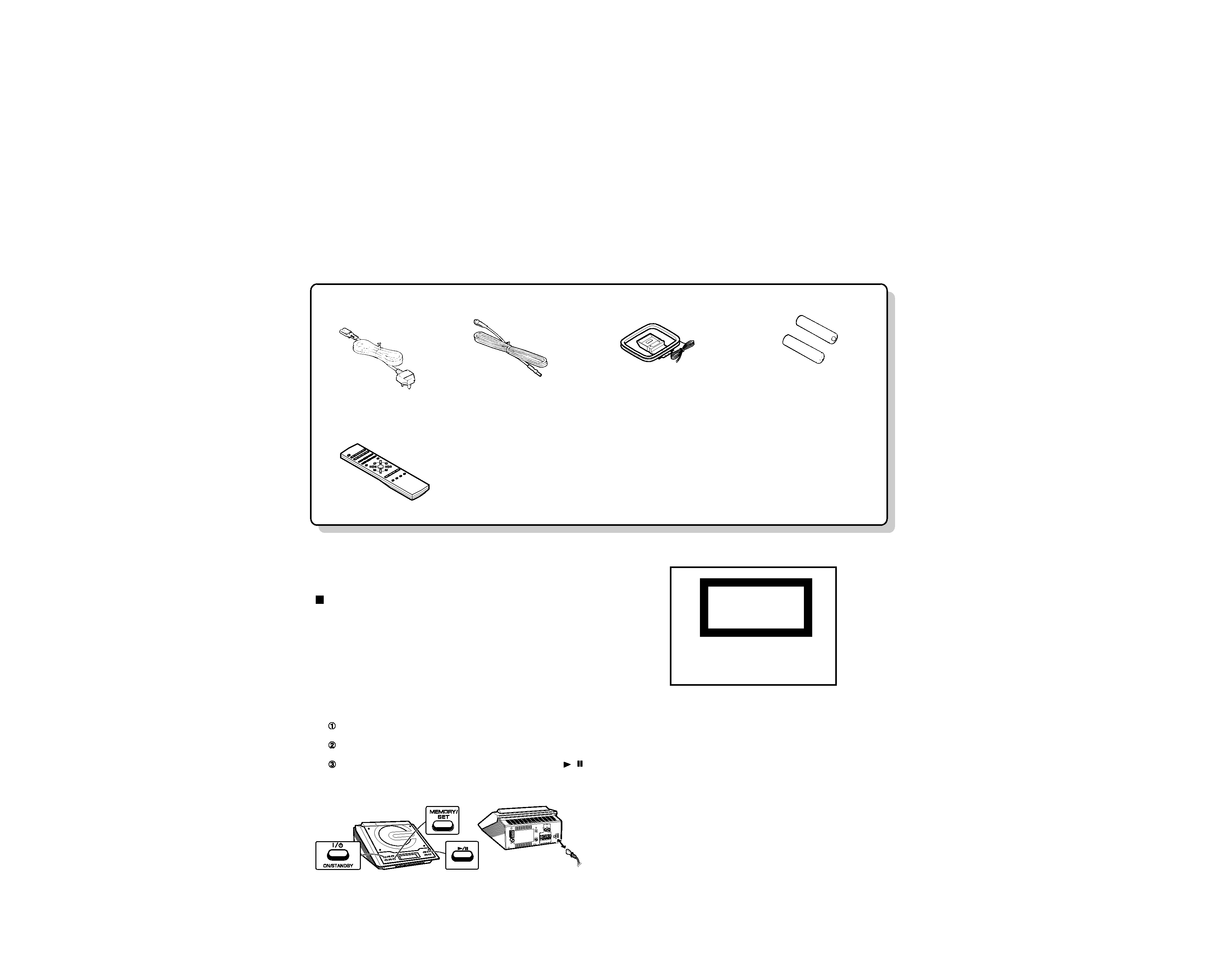
AC power lead x1
(E30-7236-08): T
(E30-7237-08): E
Remote control x1
(A70-1547-08)
Battery cover(A09-1243-08)
FM antenna x1
(T90-0891-08)
AM loop antenna x1
(T90-0890-08)
"AAA" size battery
(UM-4, R03, HP-16 or similar)x2
RD-M23
2
CONTENTS / ACCESSORIES
CONTENTS / ACCESSORIES .................................. 2
DISASSEMBLY FOR REPAIR....................................3
BLOCK DIAGRAM ......................................................5
CIRCUIT DESCRIPTION ............................................7
TROUBLE SHOOTING .............................................12
TEST MODE .............................................................15
ADJUSTMENT ..........................................................18
WAVR FORM............................................................20
PC BOARD .............................................................. 21
SCHEMATIC DIAGRAM .......................................... 26
EXPLODED VIEW ....................................................34
PARTS LIST..............................................................36
SPECIFICATIONS ......................................Back cover
Contents
Accessories
Troubleshooting
If trouble occurs
When this product is subjected to strong external interference
(mechanical shock, excessive static electricity, abnormal supply
voltage due to lightning, etc.) or if it is operated incorrectly, it may
malfunction.
If such a problem occurs, do the following:
Caution:
This operation will erase all data stored in memory including clock,
timer settings, tuner preset, and CD programme.
1
Set the unit to the stand-by mode and turn the power on
again.
2
If the unit is not restored in step 1, unplug and plug in the
unit, and then turn the power on.
3
If neither step 1 nor 2 restores the unit, do the following:
Press the ON/STAND-BY button to enter the power stand-by
mode.
Unplug the AC power lead from the AC INPUT socket on the
unit.
Whilst pressing down the MEMORY/SET button and the
/
button, plug the AC power lead into the AC INPUT socket on
the unit.
AC INPUT
CLASS 1
LASERPRODUCT
The marking
this
product
has been
classified
asClass
1.It
meansthat
there
isno danger
of hazardous
radiatio
outside t
heproduct.
RD-M23
3
DISASSEMBL
Y
FOR
REP
AIR
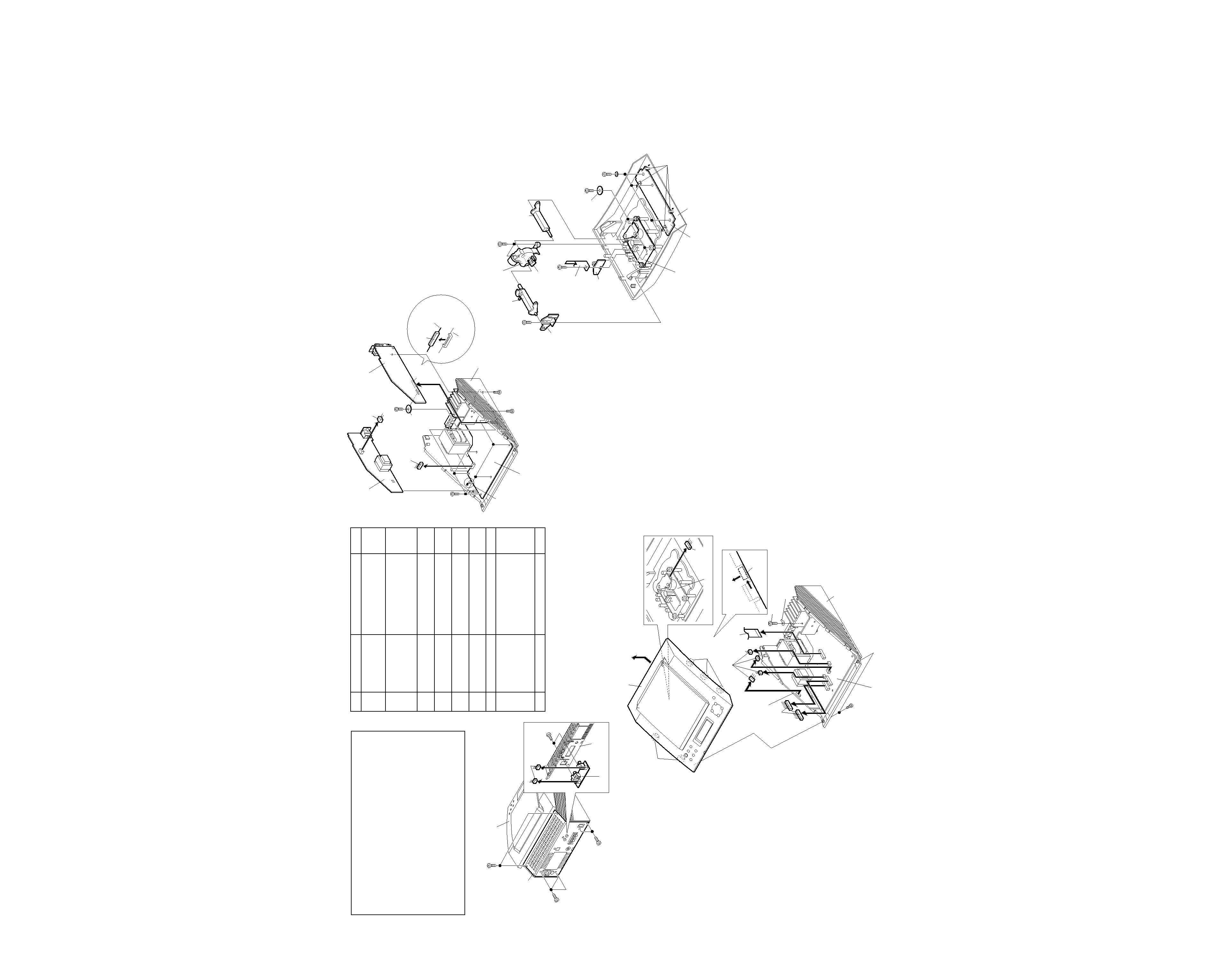
1
Rear panel/Terminal PWB 1. Screw .................. (A1) x7
8-1
2. Socket ................. (A2) x2
3. Screw .................. (A3) x3
8-1,2
2
Top cabinet
1. Screw .................. (B1) x2
8-2
2. Hook .................... (B2) x5
3. Flat Cable ............ (B3) x1
4. Socket ................. (B4) x7
3
Tuner PWB
1. Screw .................. (C1) x2
9-1
2. Socket ................. (C2) x1
4
Power PWB
1. Socket ................. (D1) x1
9-1
2. Hook .................... (D2) x1
5
Main PWB
1. Socket ................. (E1) x1
9-1
2. Screw .................. (E2) x8
6
Display PWB
1. Screw .................. (F1) x4
9-2
2. Hook .................... (F2) x4
7
CD Mechanism
1. Screw .................. (G1) x4
9-2
8
Gear Box
1. Screw .................. (H1) x1
9-2
2. Holder .................. (H2) x1
3. Lever ................... (H3) x1
4. Screw .................. (H4) x2
5. Lever ................... (H5) x1
9
LED PWB
1. Screw .................. (J1) x1
9-2
STEP
REMOVAL
PROCEDURE
FIGURE
Note:
After removing the connector for the optical pickup from the
connector, wrap the conductive aluminium foil around the
front end of connector remove to protect the optical pickup
from electrostatic damage.
Caution on Disassembly
Follow the below-mentioned notes when disassembling
the unit and reassembling it, to keep it safe and ensure
excellent performance:
1. Take compact disc out of the unit.
2. Be sure to remove the power supply plug from the wall
outlet before starting to disassemble the unit.
3. Take off nylon bands or wire holders where they need to
be removed when disassembling the unit. After servicing
the unit, be sure to rearrange the leads where they were
before disassembling.
4. Take sufficient care on static electricity of integrated
circuits and other circuits when servicing.
(A1) x2
ø3 x10mm
(A1) x3
ø3 x10mm
(A1) x2
ø3 x10mm
Rear Panel
Top Cabinet
(A2) x2
(A3) x2
ø3 x10mm
Rear Panel
Terminal PWB
Figure 8-1
(B1) x2
ø2.5 x8mm
(B4) x2
(A3) x1
ø3 x8mm
Lug
(B4) x4
(B3) x1
Hook
(B2) x3
HOOK
(B2) x2
(B4) x1
CD Mechanism
Main PWB
Power PWB
Hook
Up
Slide
Bottom Cabinet
Top Cabinet
Top Cabinet
Bottom Cabinet
Figure 8-2
(C1) x1
ø3 x8mm
(E2) x7
ø3 x8mm
(E2) x1
ø3 x14mm
(D2) x1
(C1) x1
ø3 x6mm
(D1) x1
(E1) x1
Power PWB
Holder PWB
Tuner PWB
Main PWB
(C2) x1
Tuner PWB
(C2) x1
Main PWB
Hook
Bottom Cabinet
Figure 9-1
Figure 9-2
(G1) x4
ø2.5 x10mm
(H1) x1
ø3 x8mm
(H2) x1
(H5) x1
(H4) x2
ø2.5 x10mm
(J1) x1
ø2.5 x10mm
(F1) x4
ø2.5 x10mm
Hook
(F2) x4
Display PWB
LED PWB
Switch
PWB
Gear Box
CD Mechanism
Top Cabinet
Holder PWB
(H3) x1
Bracket
RD-M23
4
DISASSEMBL
Y
FOR
REP
AIR
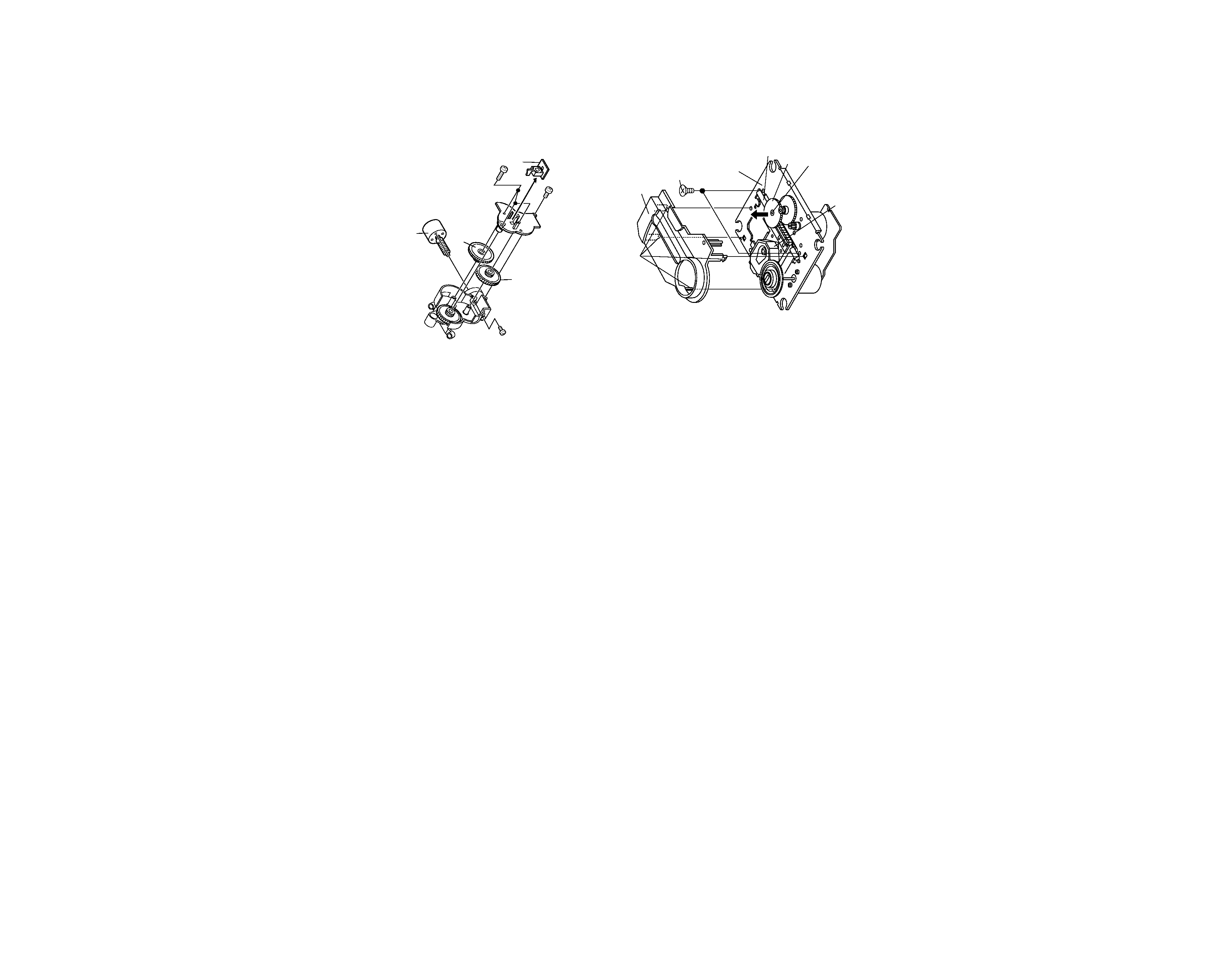
How to remove the CD lid (See Fig. 10-1.)
Perform steps 1,2 and 8 of the disassembly method to remove
the gear box.(See page 8,9)
1. Remove the switch PWB.
2. Remove the screws (A1) x 4 pcs., to remove the gear box
lid.
3. Remove the gears (A2) x 1 pc. and (A3) x 1 pc.
4. Remove the screws (A4) x 2 pcs., to remove the motor.
Caution:
Be careful so that the gear is not damaged.
(The damage gear emits noise during searching.)
Figure 10-1
Figure 10-2
(A1) x1
ø2.5 x10mm
(A1) x3
ø2.5 x12mm
(A2) x1
(A3) x1
(A4) x2
ø2 x5mm
Switch PWB
CD Lid Motor
CD MECHANISM SECTION (See Fig. 10-2.)
Perform steps 1,2 and 7 of the disassembly method to remove
the CD mechanism.(See page 8,9)
1. Remove the mechanism cover, paying attention to the
pawls (A1)x 4 pcs.
2. Remove the screws (A2) x 2 pcs., to remove the shaft (A3)
x 1 pc.
3. Remove the stop washer (A4) x 1 pc., to remove the gear
(A5) x 1 pc.
4. Remove the pickup.
Note:
After removing the connector for the optical pickup from the
connector, wrap the conductive aluminium foil around the
front end of connector remove to pretect the optical pickup
from electrostatic damage.
Pickup unit
(A2) x2
ø2.6 x6mm
(A1) x4
CD Mechanism
Shaft
(A3) x1
Gear
(A5) x1
Stop Washer
(A4) x1
Mechanism Cover
REMOVING AND REINSTALLING THE MAIN PARTS
RD-M23
5
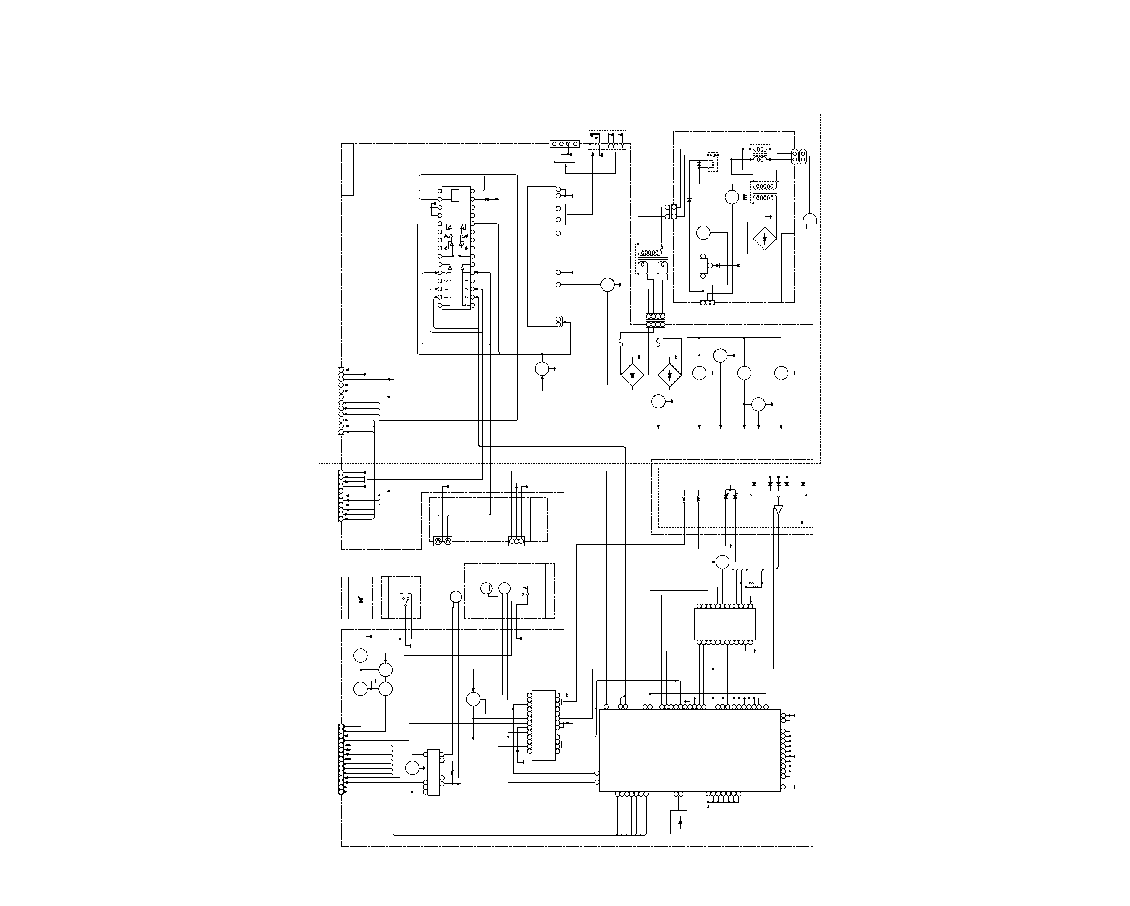
BLOCK
DIAGRAM
VOLTAGE
REGULATOR
3
1
3
2
1
USWD_5R6V
P_CONT
D_GND
3
2
1
AC INPUT
SOCKET
AC230V,50Hz
AC 230V,50Hz
AC POWER SUPPLY CORD
LINE
FILTER
POWER
TRANSFORMER
(SUB)
FROM
DISPLAY
PWB
POWER PWB-B
CNP651
SO655
LF651
IC681
AN78L05
D688
1N4004
RLY601
CNP707
T681
D681~D684
Q683
Q681
4
3
2
1
4
3
2
1
3
1
POWER
TRANSFORMER
(MAIN)
TF
T651
T2.5A L 250V
CNP801
F651
T1.25A L 250V
F653
Q606
Q607
Q904
D651~D654
D657~D660
Q801
Q101
Q102
Q601
Q602
Q605
Q603
Q604
Q608
Q609
Q903
CD +B
5V
+B
CD_6R2V
+B1
+B2
+B3
+B4
+B5
+B6
M_12V
A_12V
A_24V
5
12
9
10
11
3
7
4
2
IN2
POWER
GND1,2
VCC
OUT1
FIL
OUT2
GND
NF1
POWER AMP.
IC901
LA4282
L-CH
L-CH
R-CH
R-CH
L-CH
R-CH
SPEAKER
TERMINAL
+
+
SO601
HEADPHONES
1
2
3
4
5
9
10
J601
VSS
VDD
IC401
LC75342M
15
14
13
12
11
10
9
17
18
19
20
21
22
23
24
25
26
27
28
29
16
8
7
6
5
4
3
2
1
CE
DI
30
CL
LOGIC
TUN L
CD L
TUN R
R-CH OUT
L-CH OUT
A_12V
NC
FUNCTION/VOLUME
EQUALIZER
Q901
Q802
Q902
Q908
Q907
Q861
AUX R
AUX L
CD R
7
6
5
4
3
2
1
8 9 10 11 12 13 14 15
CNP702
CLID_SW
CLID_UP
CLID_PRO
CLID_DW
BUCK
BUS2
BUS0
BUS1
BUS3
CCE
CD_RES
PU_IN
LIGHT
CD_STB
DIMMER
SBAD
FEO
FEN
VRO
RFRP
RFIS
RFGO
RFGC
AGCI
RFO
GND
RFN
TEO
TEN
2VRO
TEB
SEL
LDO
MDI
TN1
TPI
FPI
FNI
VCC
SERVO PRE AMP.
IC801
TA2109F
SERVO/SIGNAL CONTROL
IC802
TC9462F
DOUT
TERMINAL
PWB
VSS
VSS
VSS
AVSS
XVSS
TESIOO
TESIN
TESI01
VSS
VSS
PXI
DVSL
DVSR
PDO
TMAX
VCOREV
RFI
RFCT
LPFN
LPFO
PVREV
TSIN
VREF
X801
16.93MHz
XO
XI
VDD
VDD
VDD
VDD
VDD
XVDD
AVDD
2VREF
SEL
RFGC
TEBC
FOO
TRO
TEI
TEZI
RFRP
FEI
SBAD
P2VREF
SWITCHING
MUTE
VOLTAGE
REGULATOR
VOLTAGE
REGULATOR
VOLTAGE
REGURATOR
+B6
R-CH
L-CH
SO401
VIDEO/AUX
INPUT
CD LID
MOTOR DRIVER
1
23
5
6
7
8
9
IC805
TA7291S
11 10
9 8 7 6 5 4 3 2 1
CE
CL
DI
SD
FM
ST
DO
A_12V
D_GND
TUN
L
TUN
R
A_GND
4
5
6
1
2
3
7
8
9
10 11 12
SD
STEREO
DO
CE
DI
CL
CD
+B
P_MUTE
P_STB
D_GND
5V
A_24V
+B1
+B3
+B6
+B2
+B4
+B5
CNP703
CNP307
TO
TUNER PWB
FROM
DISPLAY PWB
FROM
DISPLAY PWB
LED PWB
SWITCH PWB
CD LID
OPEN/CLOSE
SW802
D801
CD LID
OPEN/CLOSE
MOTOR
M
M801
FOCUS/TRACKING/
SPIN/SLED DRIVER
1
2
3
4
5
6
7
8
9
9
10
11
12
13
16 17 18 19
21 22 23 24 25 26 27 28
PO1-
PO1+
VO3-
VO3+
VIN3
VG3
VCC
VCC
BIAS
VG4
VIN4
VO4+
VO4-
OPO
VO2-
VO2+
VIN2
VG2
GND
GND
GND
MUTE
REG
O
TRB
VG1
VIN1
VO1+
VO1-
IC804
MM1469XH
SPINDLE
MOTOR
SLED
MOTOR
PICKUP IN
SP+
SP
SP+
SL
PU-IN
GND
FO
TR
+
+
M
M
CD MOTOR PWB
NM802
NM801
NSW801
CD_6R2V
5V
+B2
+B4
+B7
+B7
+B7
A
C
B
F
E
+B7
+B7
+B7
LD
MON
FOCUS COIL
1/2V
5V
TRACKING COIL
CD PICKUP UNIT
23
24
22
21
20
19
18
17
16
45
40
38
34
33
32
31
30
28
50
56
57
51
52
48
49
46
47
43
42
44
15
14
13
12
11
10
9
8
7
6
5
4
3
2
1
DIGITAL
OUT
3
2
1
J801
53
55
FMO
DMO
100
90
97
96
93
92
91
78
79
BUS0
BUS1
BUS2
BUS3
BUCK
/CCE
/RST
85
82
RO
LO
14
23
39
62
76
80
94
615 24
36
63 71 72 73 74 77 95
81 86
D_GND
A_GND
D_GND
D_GND
M_GND
M_GND
M_GND
M_GND
25
MAIN PWB