70%
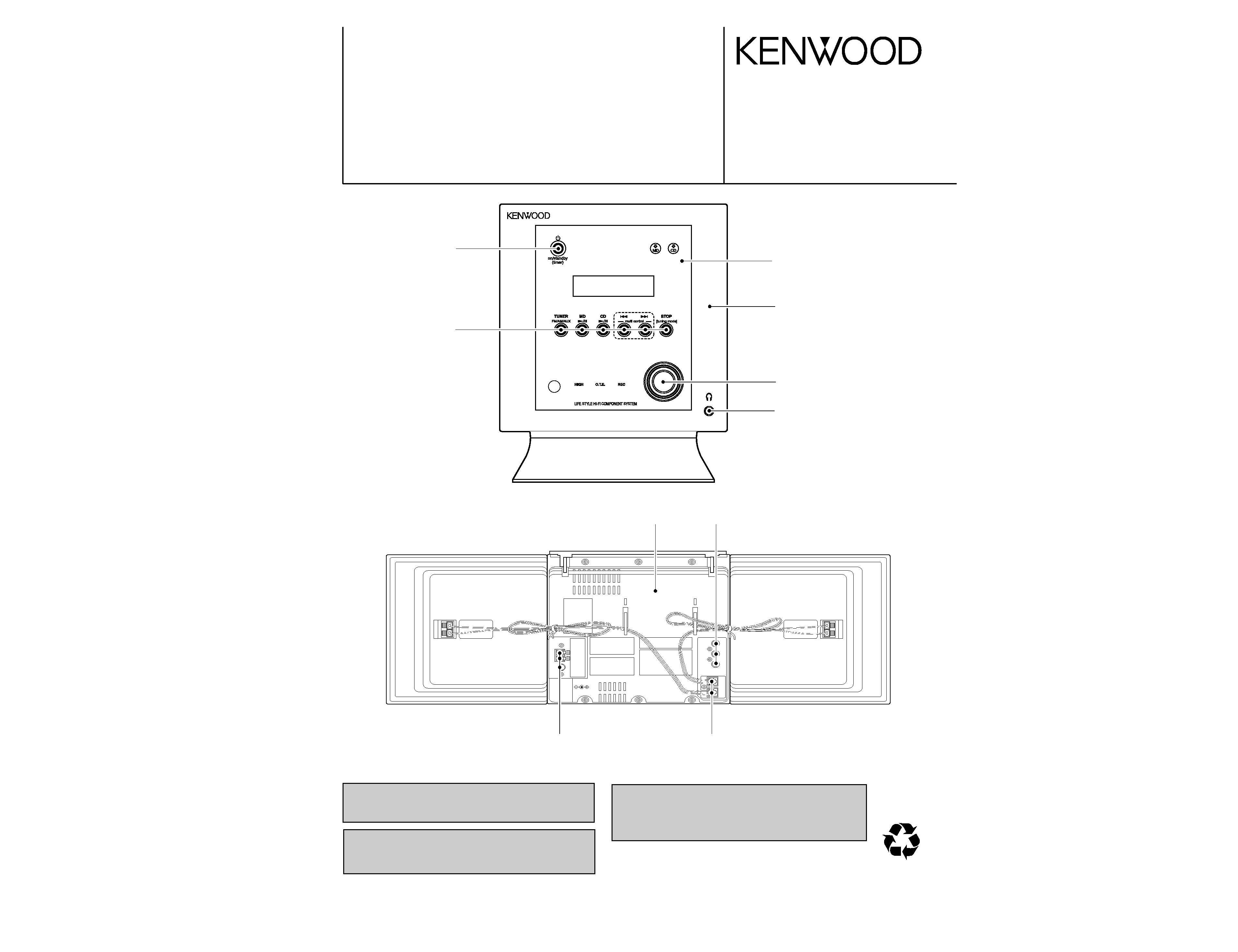
LIFE STYLE HI-FI COMPONENT SYSTEM
RD-HML700
SERVICE MANUAL
© 2003-10 PRINTED IN KOREA
B51-5879-00 (K/K) 595
In compliance with Federal Regulations, following are repro-
duction of labels on, or inside the product relating to laser
product safety.
KENWOOD Corp. certifies this equipment conforms to DHHS
Regulations No.21 CFR 1040. 10, Chapter 1, subchapter J.
DANGER : Laser radiation when open and interlock defeated.
AVOID DIRECT EXPOSURE TO BEAM.
Caution : No connection of ground line if disassemble
the unit. Please connect the ground line on
rear panel, PCBs, Chassis and some others.
(HM-L700)
SUB WOOFER
PREOUT
SPEAKER
ANTENNA
Knob
(K29-8293-03)
Cover
(F07-2019-11)
Rectangular receptacle
(E58-0061-05)
Knob
(K29-8294-04)
Knob
(K29-8298-04)
Dressing panel
(A21-5439-03)
Pin jack
(E63-1328-05)
Tuner ass'y
(W02-2980-05)
Front glass
(B10-3962-03)
Miniature phone jack
(E11-0972-05)
RD-HML700
2
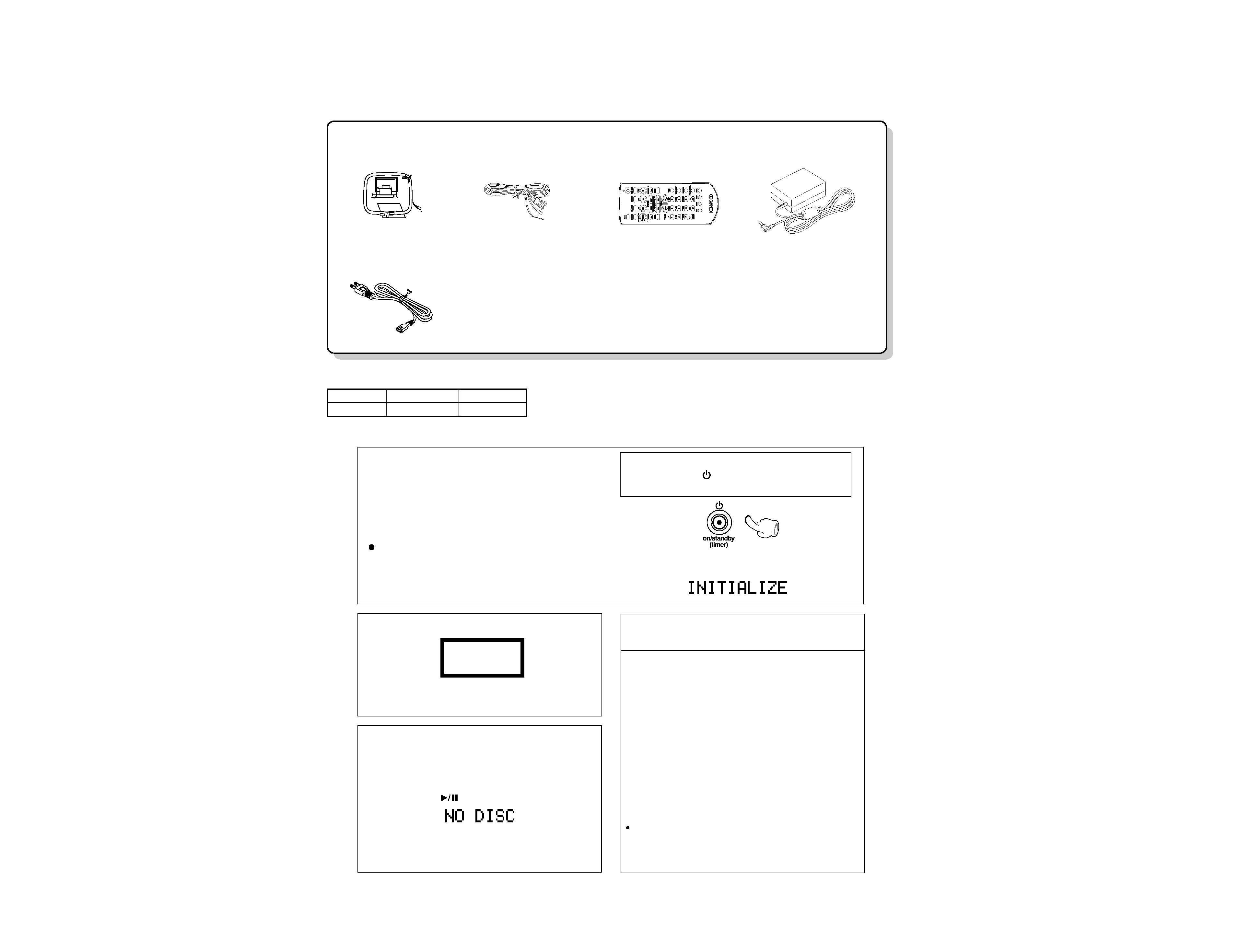
ACCESSORIES / CAUTIONS
Card-type remote control unit
(1, with built-in button battery)
(A70-1643-05)
FM indoor antenna (1)
(T90-0877-05)
AM loop antenna
(T90-0906-05)
AC adapter (1)
(W09-1299-15)
Power cord (1)
(E30-7305-05)
Accessories
Operation to reset
The microcomputer may fall into malfunction (impossi-
bility to operate, erroneous display, etc.) when the
power cord is unplugged while unit is ON or due to an
external factor. In this case, execute the following pro-
cedure to reset the microcomputer and return it to nor-
mal condition.
Unplug the power cord from the power outlet, then
while holding the
key depressed, plug the power
cord again.
Please note that resetting the microcomputer
clears the contents stored in and it returns to condi-
tion when it left the factory.
After resetting the microcomputer, the display will show
as follow:
The marking of products using lasers
The marking of this product has been classified as Class 1. It means
that there is no danger of hazardous radiation outside the product.
Location: Back panel
CLASS 1
LASER PRODUCT
1 Remove the CD from the unit.
2 Press the CD
key.
3 Wait for some time and verify that the dis-
play appears as above.
4 Wait a few seconds and turn the unit OFF.
Note related to transportation and movement
Before transporting or moving this unit, carry out the
following operations.
Memory backup function
The following information is backed up for about
1 day after the power cord is unplugged from the
wall AC outlet.
Input source
Volume setting
AUX input level setting
TONE setting
TIMER setup
Display contrast and backlight setting
Main unit CD key indicator setting
Auto power save feature setting
Tuner related
Preset radio stations
Tuning mode setting (Auto or manual)
Cautions
System Configration
SYSTEM
RECEIVER
SPEAKER
HM-L700
RD-HML700
LS-LCA7
3
AC
E
BD
2
1
3
5
7
4
6
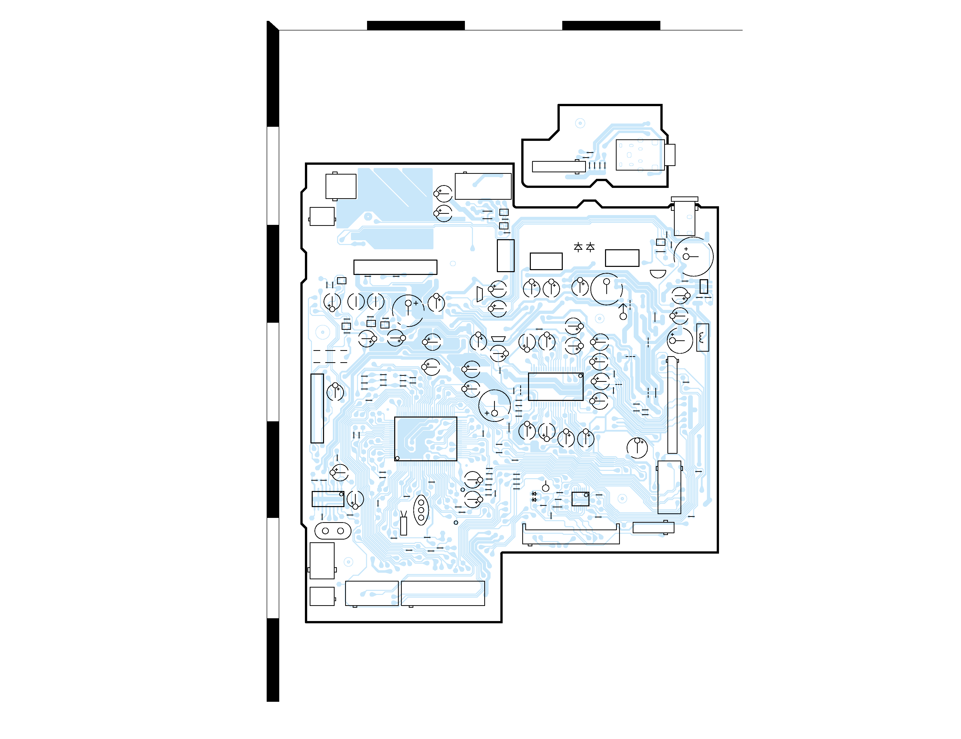
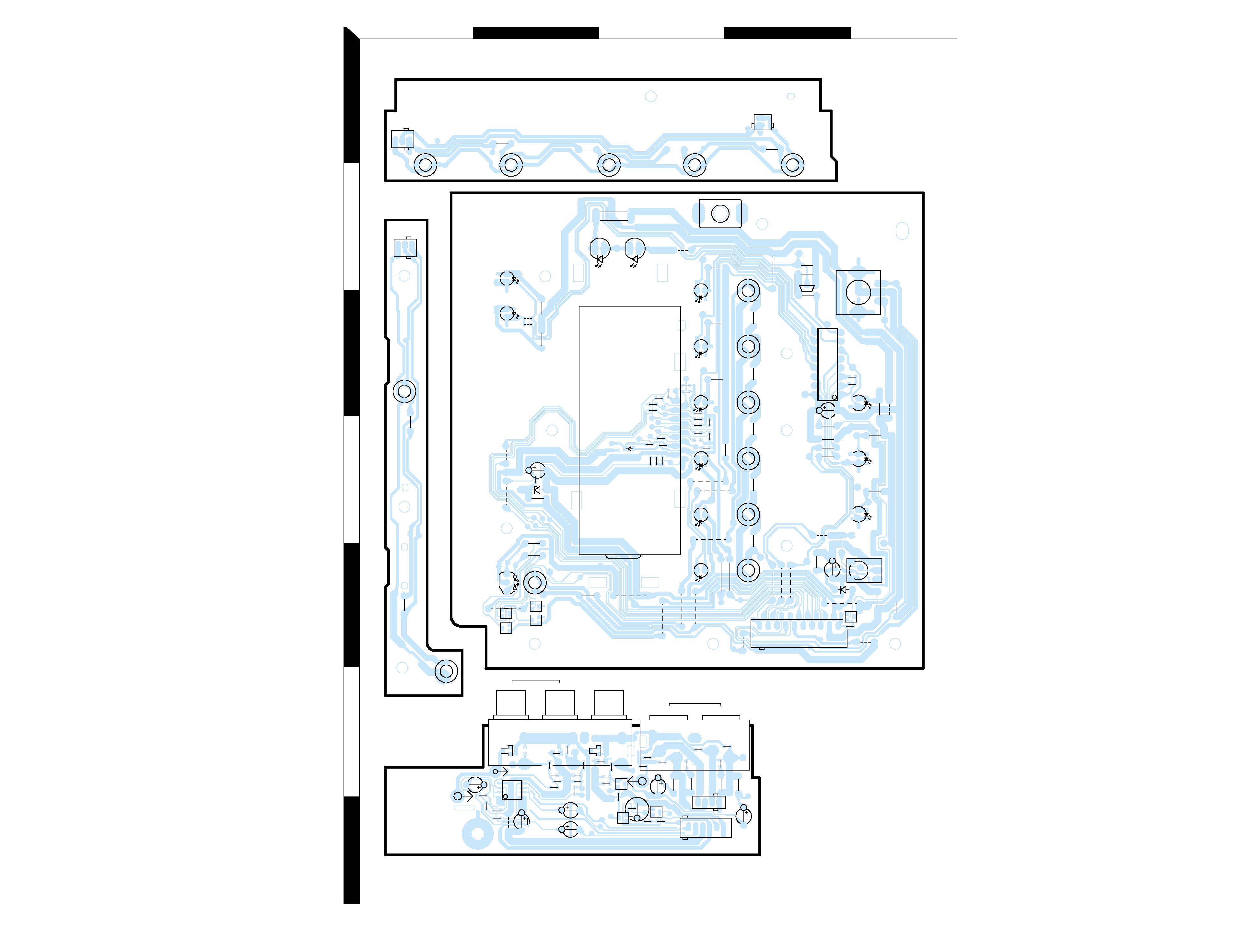
Refer
to
the
schematic
diagram
for
the
value
of
resistors
and
capacitors.
PC
BOARD
C605
C41
1
R41
1
R515
R518
R516
R51
1
C412
R412
R514
R519
R421
R517
R222
R220
C421
R221
R520
R230
R228
R227
R215
R268
R243
R241
R240
R231
R250
R278
R804
R279
R203
R204
R201
R207
R256
C216
R277
R229
R213
R202
R208
R249
C803
C804
C805
R258
R802
R122
W24
R513
W11
R20
L403
W1
W12
R19
R342
R343
L402
W13
R61
C35
W26
R62
C62
C36
C61
R45
C371
R373
R341
R351
R123
C606
18
R124
C1
16
C1
15
R155
R151
R246
R244
R248
R247
R245
R152
R234
C209
C208
C207
R238
R236
R154
R153
R121
C152
R602
R601
C602
C601
DISP.
E.VOL
TUNER
C422
C12
CD
C14
C13
C34
C22
C282
BUSY1
4.332MHz
X201
FLASH
RDS
11
5
2
X801
MRXD
X202
C281
C284
C801
C811
DOOR DRIVE
C551
C51
C321
C401
MD
L405
C402
C341
C19
C42
C52
C332
C43
C1
1
C21
C322
C33
C311
B
EB
E
OG
I
G
O
I
G
O
B
E
I
C111
C110
C294
C301
C293
C38
C302
C102
C109
R553
C37
R554
C151
C101
C122
C121
AMP
.
POWER
PHONE
HEAD
E
B
EB
EB
E
B
EB
EB
EB
R261
R263
9
91
12
1
1
1
8
12
4
16
1
8
1
30
80
51
31
50
100
81
1
7
8
14
1
1
1
1
29
1
28
2
1
19
2
18
6
11
10
2
29
28
2
21
42
22
4
5
3
1
C331
32.768kHz
10MHz
C312
C20
D423
D422
Q352
Q121
Q122
Q152
Q154
Q151
Q153
CN411
WH11
CN455
CN401
WH2
CN201
CN901
CN202
CN551
WH1
Q51
J351
Q351
D311
D331
WH601
Q361
CN101
CN552
CN102
J601
PHONES
IC201
IC511
IC11
IC801
IC341
IC551
IC321
IC331
IC311
IC101
X09 B/2
X09-6812-71 A/2 (J70-1695-12) (SIDE-A)
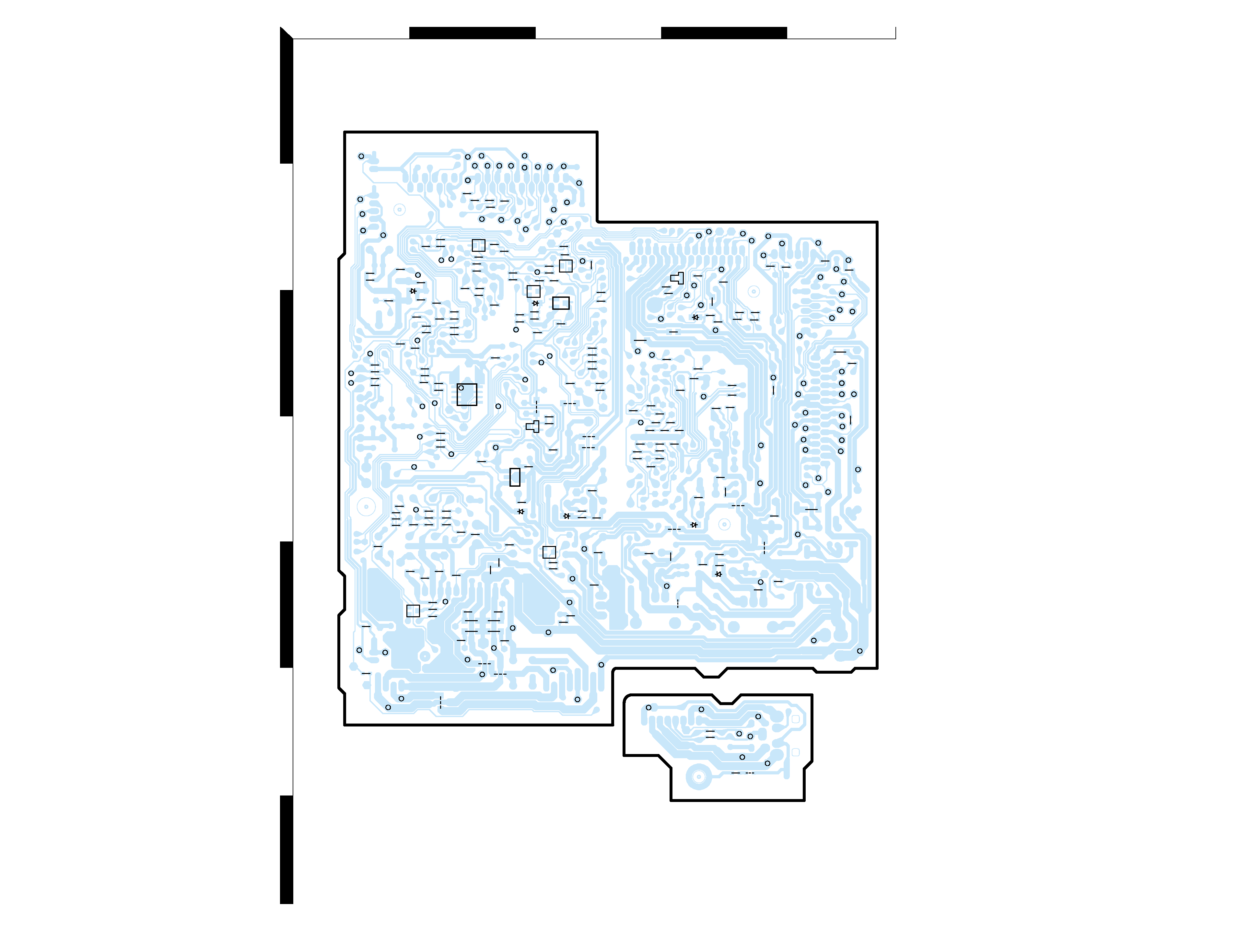
Refer
to
the
schematic
diagram
for
the
value
of
resistors
and
capacitors.
PC
BOARD
4
F
GI
HJ
2
1
3
5
7
4
6
D45
Q362
D321
Q155
D424
D421
D301
D51
D281
D282
Q281
Q271
D811
Q272
IC281
IC301
IC901
X09-6812-71 A/2 (J70-1695-12) (SIDE-B)
X09 B/2
R272
C1
12
R161
W4
C603
R604
R603
R323
C351
W14
R371
R332
W3
R.IN
L.OUT
L.IN
HP.L
HP.R
R.OUT
GND
HP.GND
HP.R
10V
9.5V
CD.5V
L+IN
ST-BY
MID
D2
VREF
AVR.P
RDS CLK
CD DOWN
EJC
GND
DATA
REMO
STBY
CK
CLK
TIMER
KEY1
DT
RS
CD LED
GND
10V
5.8V
SLOT+
BUSY1
DT IN
LRCK
RST
TNO
D.GND
CD A.5V
CLK
DT OUT
XT0
CDR
AUX R
GND
AUX L
NC
9V
9V
Lch
CLK
RST
D.GND
A.GND
5V
NC
6.3V
NC
H.5V
DATA
BCK
9V
6.3V
MD.5V
10V
CD/MD 6.3V
D.GND
LRCK
DIN2
DIN1
OUT L
OUT
R
IN L
IN R
CE
RXD
CE
DI
DO
GND
MD 3.3V
CD L
E.DT
M.GND
MD LED
SLOT-
CS
RST
E.B
E.A
CE
CD IN
BUSY2
CD.POW
POWER
OPEN
D1
SCL
A.MUTE
ALARM
RDS DT
SDA
GND
L-
R+IN
R-
L+
M-
M+
R+
HP.L
W17
R331
R322
R321
C323
C313
R312
W18
R105
C108
C107
C105
R372
R109
R107
W15
W16
C106
R1
10
R108
C361
R156
R361
C1
14
R127
R162
C104
C123
R126
R1
1
1
C552
C1
17
C1
18
C1
13
C103
R157
R164
R281
R242
R16
C30
C125
W23
L401
C39
C404
C40
R422
R15
R12
C25
R11
R46
R23
R53
R52
R51
C53
C29
C27
R21
C31
C26
C24
C23
C46
C45
R24
C48
C47
C32
R22
C802
C28
C425
R431
L404
R413
R432
C432
C431
C451
C452
R18
R17
C423
R284
C511
L421
R13
R14
W31
R423
L41
1
R424
W2
R512
C424
R285
R225
R223
R217
R269
R101
R302
R301
R291
R102
R106
R237
R104
C303
C292
W25
W19
R292
W20
W21
R803
R286
R235
R233
R163
C162
C161
R103
C210
R902
R901
C212
R812
R209
R239
R270
R282
R219
R283
C283
C206
R266
R259
R257
R232
R265
R212
R21
1
C205
R274
C203
C215
C214
R206
R273
C202
R81
1
R552
R551
R556
R555
C126
R125
R260
R801
C213
C21
1
C808
C807
C806
R252
R255
R251
R254
R253
R210
C204
R262
R264
R205
R271
R214
R276
R275
1
4
8
5
IG O
B
E
GO
I
B
E
B
E
BE
BE
GND
TU R
KEY2
MID SW
CLOSE SW
OPEN SW
GND
CLOSE
5.8V
5
KM
O
LN
2
1
3
5
7
4
6
Refer
to
the
schematic
diagram
for
the
value
of
resistors
and
capacitors.
PC
BOARD
W102
C1
1
C3
C4
R39
C9
C15
C6
C8
C7
C13
C16
C14
C12
R42
R38
R37
R36
R61
R43
R44
C17
214
1
1
19
1
18
16
9
5
3
4
18
2
13
R35
C5
W101
R41
R58
R45
C104
C105
C101
C102
C103
1
6
14
C60
C59
R57
L2
R54
C54
R52
C61
R48
R59
R49
R63
C51
C52
L1
R53
C53 R51
R65
R66
R62
C56
C55
R64
R28
HIGH
O.T.E
W7
W21
W16
R1
C58
R56
R68
R
C64
C62
C63
C57
R67
R55
L
W10
W3
R14
W9
C1
R13
W13
W11
W12
TUNER/AUX
W2
W6
W5
W4
R18
R17
W15
W14
C65
W1
C66
POWER
W8
R6
R15
R16
CD EJECT
R11
C2
R3
R2
R23
MD
R32
R34
R33
R24
R46
R25
CD
W18
W19
R19
R5
R4
REC
DOWN
UP
R31
B
E
R30
1
13
13
2
R20
R21
R22
R40
W17
C10
W20
R27
R26
R12
DOOR OPEN/CLOSE
W22
MD
EJECT/OPEN
R10
W23
R60
R29
R9
ENTER/DEMO
R8
MODE
MD
REC
O.T
.E
R7
R47
14
85
B
E
BE
B
E
B
E
B
E
BE
B
E
BE
D18
Q3
Q2
D19
Q4
Q5
Q8
Q10
Q9
Q7
D20
A1
CN2
WH3
J2
WH50
CN1
D17
S1
D5
J1
WH51
WH50
L
R
AU
X
SUB
W
OOFER
PRE
OUT
L
R
SPEKERS
S7
D1
S13
D10
D9
D11
S2
D3
S3
D4
S15
Q1
S4
D6
S5
D7
D8
S6
ED1
D16
D13
D12
S14
WH2-1
S11
S12
WH1
P1
D15
S10
S8
D14
S9
WH2-2
IC2
IC1
X14 B/4
X14 C/4
X14-7722-71 A/4 (J70-1696-12)
X14 D/4