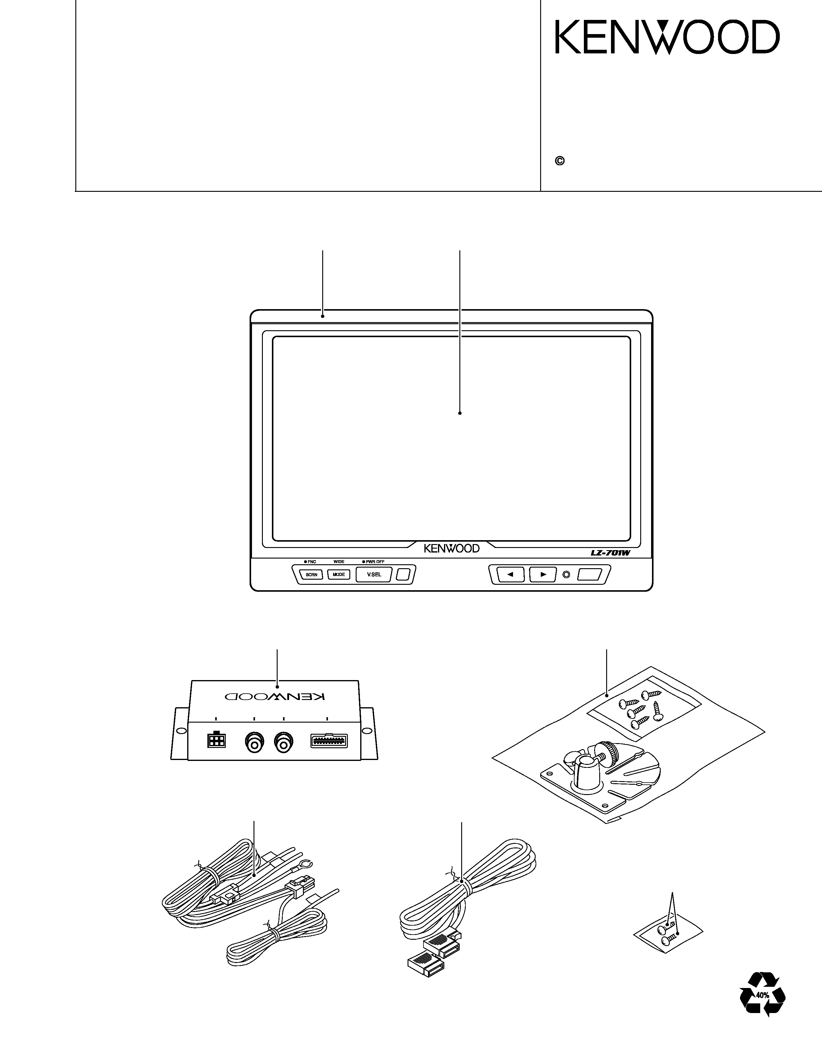
7.0-inch WIDE COLOR LCD MONITOR
LZ-701W
SERVICE MANUAL
2001-6 PRINTED IN JAPAN
B51-7821-00 (N) 3393
7.0-inch WIDE COLOR LCD MONITOR
Panel assy
(A64-2638-08)
TOMONITOR
UNIT
VIDEOIN
VIDEOOUT
POWER
Display module assy
(W02-3322-08)
Case assy
(A01-2789-08)
Stand assy
(W01-1508-05)
DC cord
(E30-6038-08)
Cord with plug
(E30-6037-08)
Screw
(N46-4016-45) x2
LZ-701W
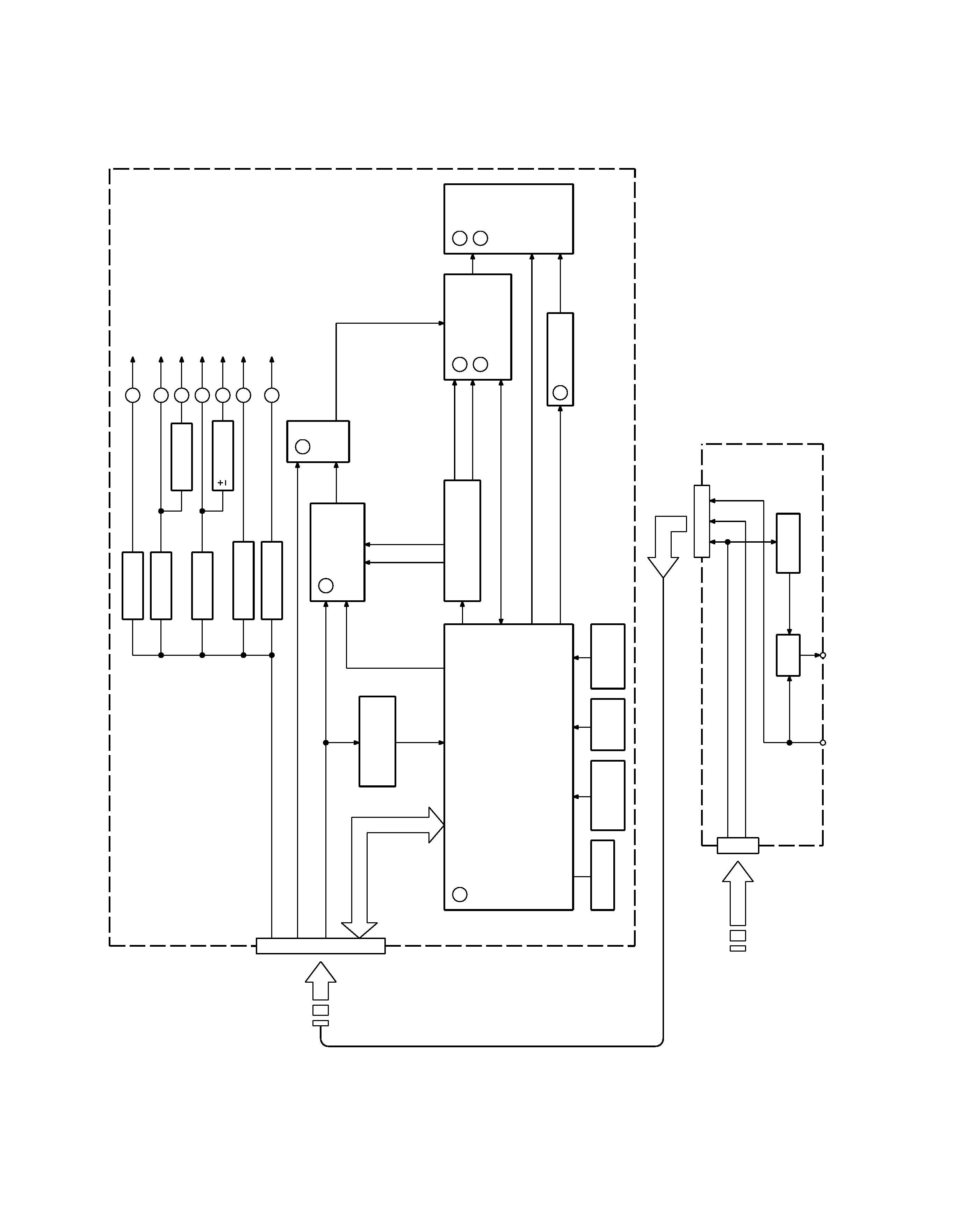
BLOCK
DIAGRAM
OSD u-COM
M37212
A
EPROM
REMOTE
SENSOR
KEY
INPUT
DIMMER
SENSOR
INVERTER
G
B
LCD I/F
IR3Y26A1
CF
7 inch
LCD
E
ELECTRONIC VOL.
UPD1830
F
NTSC/PAL
CHROMA
DISTINCTION
NTSC/PAL
D
SW
8.5V DC-DC
G
5.0V DC-DC
F
16V REG
E
8.5V REG.
D
5.0V REG.
C
7.5V REG.
B
5.0V REG.
A
VCC (OSD u-COM)
LCD I/F
LCD I/F
SW
LCD
LCD,AVCC (CHROMA)
INVERTER
AMP
5V REG.
POWER CABLE
2
BRIGHTNESS,DIMMER (PWM)
NTSC/PAL,MODE
CONTRAST
BLACK (BRIGHT)
OSD
H-SYNC/V-SYNC
(6
wire)
COMMUNICATION
NTSC/PAL
NTSC/PAL
VIDEO
RGB
RGB
COLOR
TINT(NTSC)
ACC
ACC
PARKING
VIDEO
VIDEO IN
VIDEO OUT
CABLE for LZ-701W (to LCD MONITOR)
VIDEO
VIDEO
LCD MONITOR
HIDEAWAY BOX
LZ-701W
2
LZ-701W
3
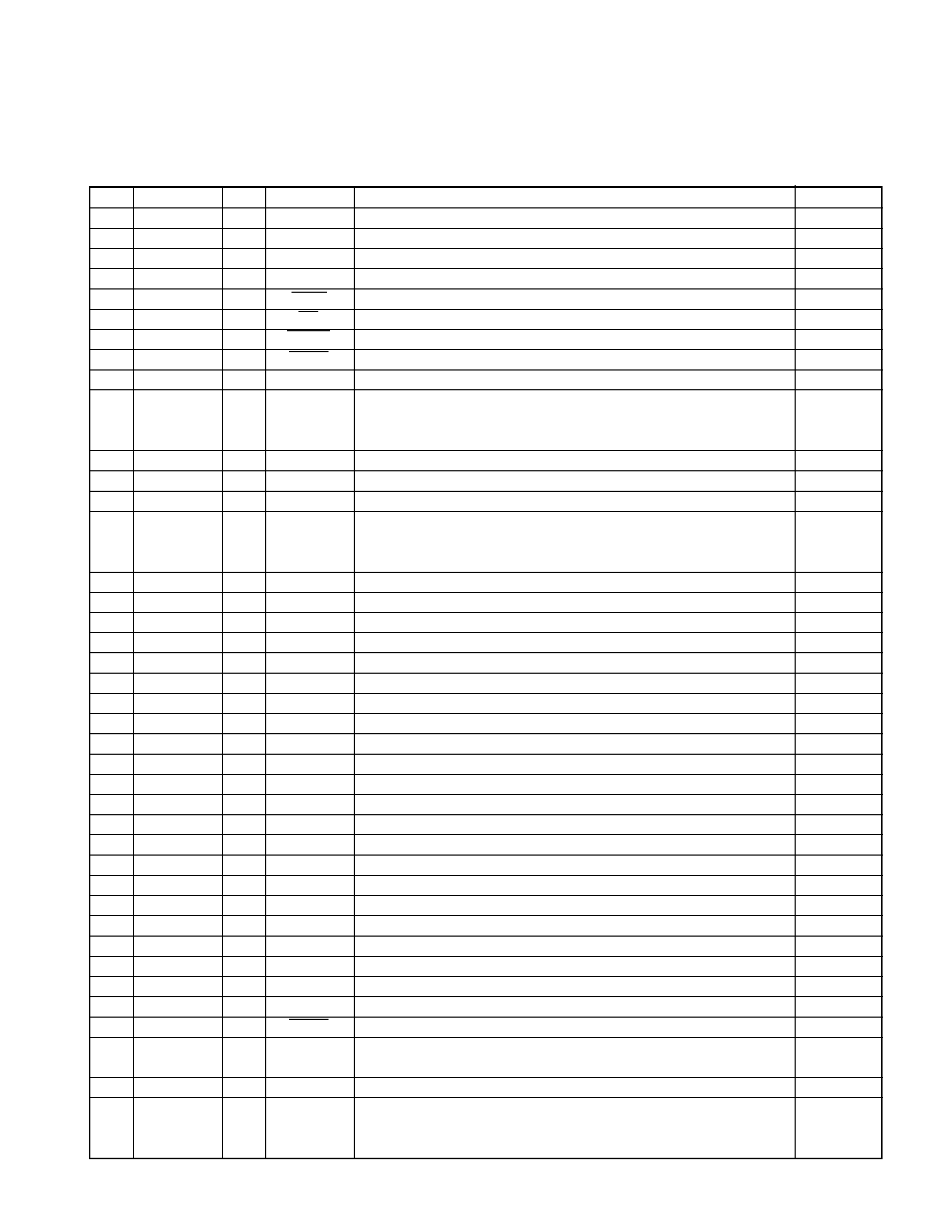
TERMINAL DESCRIPTION
OSD Microcomputer (M37212EFFP : IC101)
Pin Functions
No.
Port name
I/O
Signal name
Function
P-U, P-D
1NC
2NC
3NC
4NC
5
P00
I
SCRN
"SCRN" key input. ACT "L".
PULL UP
6
P01
I
UP
">" key input. ACT "L".
PULL UP
7
P02
I
DOWN
"<" key input. ACT "L".
PULL UP
8
P03
I
MODE
"MODE" key input. ACT "L".
PULL UP
9NC
10
A-D5
I
TEMP
Temperature sensor input.
PULL UP
When the voltage is 1.5 V or more in CINEMA/ZOOM mode,
the VCOM amplitude is increased.
11
Not use.
12
Not use.
13
Not use.
14
INT2
I
VIN
NTSC/PAL identification input
PULL UP
NTSC or PAL is identified according to the input V-SYNC frequency
and the output at pin 58 is switched accordingly.
15
INT1
I
SC_REQ
TV microcomputer communication port.
16
P33
I
RMC
Remote control input.
17
Not use.
18
P24
O
MC_CLK
TV microcomputer communication port.
19
Not use.
20
P26
I
SC_DATA
TV microcomputer communication port.
21
NC
22
NC
23
NC
24
NC
25
NC
26
NC
27
Not use.
28
CNVSS
CNVSS
GND
29
X_IN
I
XIN
Main clock oscillation input.
30
X_OUT
O
XOUT
Main clock oscillation output. 8 MHz.
31
VSS
VSS
GND
32
NC
33
NC
34
VCC
VCC
Supply voltage. +5 V +/-10%.
35
Not use.
36
Not use.
37
RESET
I
RESET
Reset input.
38
P31
O
RGB/V
RGB/Video identification input. When the TV tuner is connected, H: RGB.
PULL DOWN
When the hideaway box is connected, L: VIDEO.
39
NC
40
P30
I
PARK
Parking input. H: Parking. L: Running.
PULL DOWN
When "L" is input, the "ATTENTION" OSD appears.
This is invalid when the TV tuner is connected.
LZ-701W
4
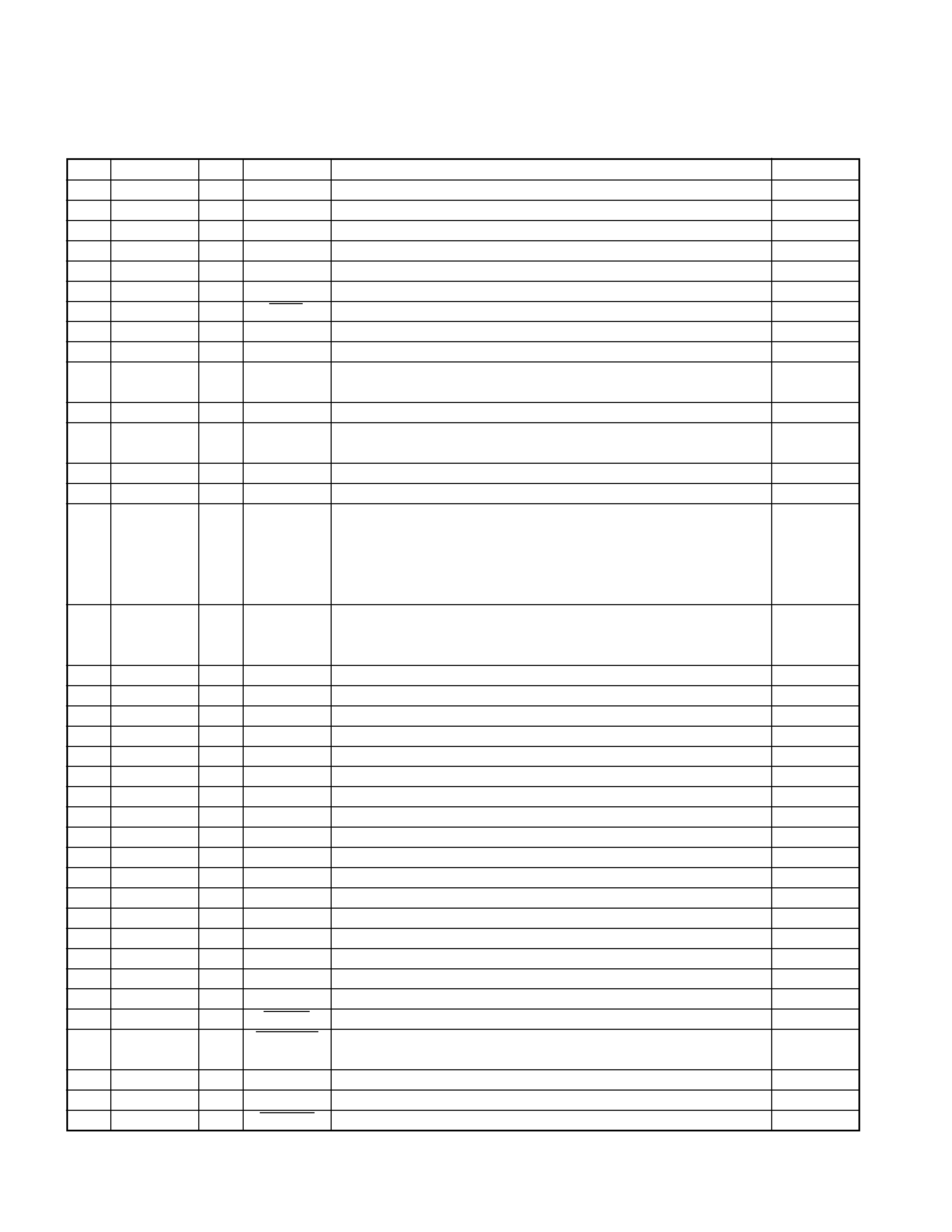
TERMINAL DESCRIPTION
Pin Functions
No.
Port name
I/O
Signal name
Function
P-U, P-D
41
NC
42
NC
43
NC
44
NC
45
Not use.
46
A-D2
I
DIMIN
Dimmer sensor input. High voltage (Bright) - Low voltage (Dimmed).
47
INT3
I
V.SEL
V SEL (PWR)" key input. ACT "L".
PULL UP
48
NC
49
Not use.
50
SDA1
SDA
IIC bus communication port. *For use in EEPROM and DAC control.
PULL UP
EEPROM: HN58X2402FPI-Z. DAC: M62334FP.
51
Not use.
52
SCL1
SCL
IIC bus communication port. *For use in EEPROM and DAC control.
PULL UP
EEPROM: HN58X2402FPI-Z. DAC: M62334FP.
53
NC
54
Not use.
LCD screen mode output. (S,N,W) = (H,H,H) : Full
55
P07
O
MODS
(H,H,L) : Normal
PULL UP
56
P06
O
MODN
(H,L,H) : Just
PULL UP
57
P05
O
MODW
(H,L,L) : Cinema
PULL UP
(L,H,H) : Zoom
58
P04
O
N/P
NTSC/PAL switching output. H: NTSC. L: PAL.
PULL UP
This output is switched according to the input at pin 14 regardless of
whether thetuner is connected or not.
59
P23
O
SC_CON
TV microcomputer communication ports.
60
P22
O
MC_CREQ
TV microcomputer communication ports.
61
NC
62
NC
63
NC
64
NC
65
P21
O
MC_DATA
TV microcomputer communication port.
66
NC
67
Not use.
68
OUT1
O
BLK
OSD blanking output (positive polarity).
PULL DOWN
69
B
O
B
OSD Blue output (positive polarity).
70
G
O
G
OSD Green output (positive polarity).
71
R
O
R
OSD Red output (positive polarity).
72
NC
73
NC
74
H_SYNC
I
HSYNC
OSD Horizontal sync signal input.
75
V_SYNC
I
VSYNC
OSD Vertical sync signal input.
76
P60
O
POWER
Power ON/OFF output. L: ON. H: OFF.
PULL UP
77
P61
O
CONNECT
Connection confirmation output.
PULL UP
H: Tuner connected. L: Hideaway box connected.
78
P62
O
DIMOUT
Backlight dimmer output.
PULL UP
79
NC
80
P63
O
POWER2
Power ON/OFF output. L: ON. H: OFF.
PULL UP

LZ-701W
5
TEST MODE / CIRCUIT DESCRIPTION
Test Mode and Initialization
While holding the [SCRN] and [>] keys, reset (switch
on the power supply to)
the system to initialize it and enter the test mode.
(1) Initial condition
* Output source when the tuner is connected: TV mode
* Wide mode: Full [Full mode]
* Brightness: 31 (Max.) [Full mode]
* Tint/Color/Contrast/Black Level: 11 (Center) [Full mode]
* Dimmer: 31 (Max.) [Full mode]
* AV OUT switching: Normal
* FM-TX output: OFF
* Remote: ON
* Power ON/OFF: OFF
(2) Operations in test mode
· Power is ON.
· All of the screen adjustment items can be adjusted in
3 steps of Min., Center and Max. (Both Display and
DAC output)
· The value of the dimmer sensor input affects imme-
diately the output value.
· Other operations are identical to those in normal
modes.
· The communication with the tuner is held in the same
way as in normal modes. However, the Tint and Color
values are changed to the Center values by activating
communication after the EEPROM resetting. Their val-
ues can be adjusted in 3 steps (Min., Center, Max.).
· Storage in the EEPROM is not performed in any op-
eration in the test mode.
(3) Switching the power supply OFF in the test mode
turns the system into the shipment condition.
Circuit Description
1. Identification and switching
of tuner/hideaway box
The OSD microcomputer (IC101) communicates with
the tuner unit through the communication line (pins
15, 18, 20, 59, 60 and 65). When the communication
cannot be established, the microcomputer identifies
that the connected unit is the hideaway box.
· When the tuner is connected:
The input to IC206 is switched to the External RGB
position. Q007 is turned OFF to shut off the power
supply to the chroma block.
· When the hideaway box is connected:
The input to IC206 is switched to the Chroma RGB
position. Q007 is turned ON to supply the +5 V power
to the chroma block.
2. NTSC/PAL input identification
When the hideaway box is connected, the sync in the
input video signal is separated at IC204. The vertical
sync signal is input to the microcomputer (IC101: Pin
14), which identifies the NTSC or PAL format accord-
ing to the vertical sync frequency.
3. Chroma circuit
The chroma circuit functions only when the hideaway
box is connected. Chroma IC IC201 receives the com-
posite signal from pin 36 and sync separation signal
from pin 39, and converts the composite signal to RGB
signals, which are output at pins 23, 24 and 25.
4. LCD interface circuit
LCD Interface IC IC301 receives the video RGB sig-
nals from pins 6, 8 and 10, and receives the OSD RGB
signals from pins 13, 14 and 15. The IC converts the
input signals into the LCD RGB signals and outputs
them at pins 29, 32 and 35. This IC also performs the
gamma correction, RGB amplitude adjustment and
VCOM amplitude adjustment.
5. Screen adjustment
DAC IC IC105 varies the output voltage to assist the
screen adjustment.
Pin 1 varies the voltage at pin 41 of IC301 during the
black level adjustment.
Pin 2 varies the voltage at pin 5 of IC301 during the
contrast adjustment.
Pin 3 varies the output voltage at pin 21 of IC 201
during the TINT adjustment, which is possible when
the hideaway box is connected.
Pin 4 varies the output voltage at pin 20 of IC201 dur-
ing the color adjustment, which is possible when the
hideaway box is connected.
6. Power supply circuit
When power is supplied from the tuner unit or hide-
away box, IC001 is activated to supply power to the
OSD microcomputer (IC101).
When power is
switched ON, IC101 activates the power supply cir-
cuitry. When Q001 goes ON, the main power is sup-
plied to the power supply circuitry. IC003 supplies
+5 V (for the chroma block and LCD module).
Q003 supplies +8 V (for the RGB SW).
Q005 supplies +7.5 V/+5 V (for the LCD interface cir-
cuit).
IC002 supplies +/-16 V (for the LCD module).