
B64-1449-00 (E) (DT) `99/6
KTC-1000R
HIDEAWAY TUNER AMPLIFIER
INSTRUCTION MANUAL

Safety precautions
2 English
To prevent injury and/or fire, take the
following precautions:
· Ensure that the unit is securely installed.
Otherwise it may fly out of place during
collisions and other jolts.
· When extending the ignition, battery or ground
cables, make sure to use automotive-grade
cables or other cables with an area of 0.75mm2
(AWG18) or more to prevent cable deterioration
and damage to the cable coating.
· To prevent short circuits, never put or leave any
metallic objects (e.g., coins or metal tools)
inside the unit.
· If the unit starts to emit smoke or strange
smells, turn off the power immediately and
consult your Kenwood dealer.
To prevent damage to the machine, take
the following precautions:
· Make sure to ground the unit to a negative 12V
DC power supply.
· Do not open the top or bottom covers of the
unit.
· Do not install the unit in a spot exposed to
direct sunlight or excessive heat or humidity.
Also avoid places with too much dust or the
possibility of water splashing.
· When replacing a fuse, only use a new one
with the prescribed rating. Using a fuse with
the wrong rating may cause your unit to
malfunction.
· To prevent short circuits when replacing a fuse,
first disconnect the wiring harness.
· During installation, do not use any screws
except for the ones provided. The use of
improper screws might result in damage to the
main unit.
· When drilling a hole in the car to fix the
brackets, make sure not to damage the fuel
tank, brake tube, wiring harnesses, etc. on
the other side.
If you experience problems during installation,
consult your Kenwood dealer.
Cleaning the Unit
If the surface is dirty, wipe it clean with a
silicon cloth or soft dry cloth with the power
off.
Do not use hard cloths or paint thinner, alcohol,
or other volatile solvents.
IMPORTANT INFORMATION
Models which can be connected with this
device are those that went on sale from 1998
(mentioned below). (As of June, 1999).
s Audio systems for controlling this set
This set is operated with a control unit, and
does not have its own controls.
The set can be operated with the following
control units.
KVC-1000, VZ907#1,2
s CD player
KDC-D300
s CD auto changer
KDC-C712, KDC-C711
KDC-C662, KDC-C462, KDC-C661
KDC-CPS82#2, KDC-CPS81#2,3
C907#3
s MD auto changer
KMD-D400
s DAB tuner
KTC-959DAB#1
s CD/MD changer switching unit with
auxiliary RCA stereo input
KCA-S210A#2
· If the relevant connected device has a
PROTOCOL SWITCH or O-N SWITCH, be sure
to set the switch to "N". Operation will fail if set
to "O".
· It is possible to interconnect 2 CD/MD
changers via the MZ-BUS and 5L interface.#3
· Cannot be connected to Kenwood disc
changers (those that went on sale from 1997)
or those manufactured by other companies,
and without a "O-N" switch.
#1:The KTC-959DAB cannot be used with the
VZ907.
#2:AUX operation is not possible with the VZ907.
#3:Do not connect the C907 and KDC-CPS81 at
the same time. The equipment will cease
functioning.
NOTE
2CAUTION
NOTE
2CAUTION
2WARNING
Installation
English
3
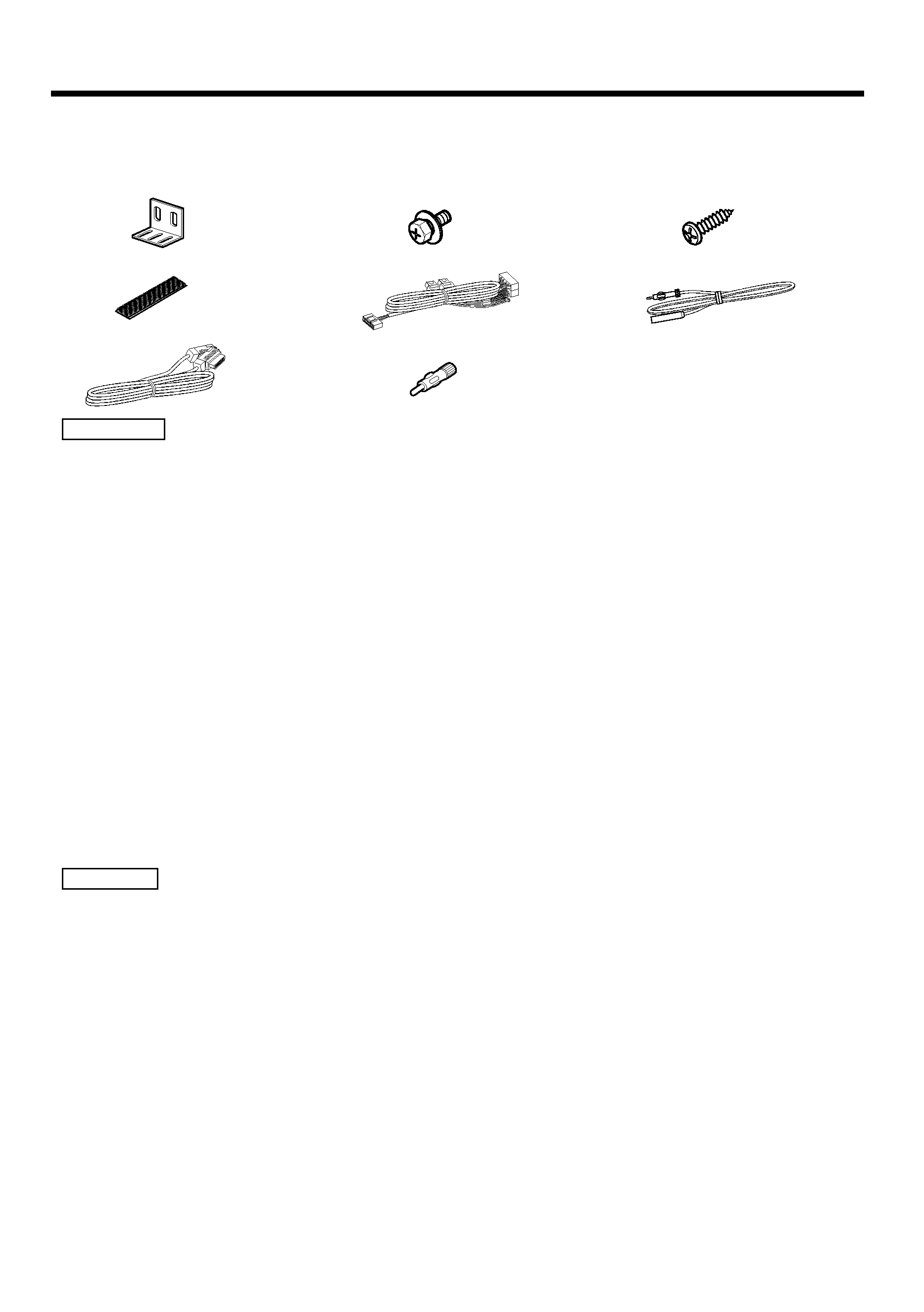
The use of any accessories except for those provided might result in damage to the unit. Make
sure only to use the accessories shipped with the unit, as shown above.
2CAUTION
.........2
1
.........2
4
.........1
7
External view
......... Number of items
.........4
2
.........1
5
.........1
8
External view
......... Number of items
External view
......... Number of items
.........4
3
.........1
6
Accessories
s
1. To prevent short circuits, remove the key
from the ignition and disconnect the -
terminal of the battery.
2. Make the proper input and output cable
connections for each unit.
3. Connect the speaker cables of the wiring
harness.
4. Take Connector B on the wiring harness and
connect it to the speaker connector in your
vehicle.
5. Take Connector A on the wiring harness and
connect it to the external power connector on
your vehicle.
6. Install the unit in your car.
7. Reconnect the - terminal of the battery.
8. Press the reset button.
· If your car is not prepared for this special
connection-system, consult your KENWOOD
dealer.
· Only use antenna conversion adapters (ISO-
JASO) when the antenna cord has an ISO
plug.
· Make sure that all cable connections are
securely made by inserting jacks until they
lock completely.
· If your vehicle's ignition does not have an
ACC position, or if the ignition cable is
connected to a power source with constant
voltage such as a battery cable, the power
will not be linked with the ignition (i.e., it will
not turn on and off along with the ignition). If
you want to link the unit's power with the
ignition, connect the ignition cable to a
power source that can be turned on and off
with the ignition key.
· If the fuse blows, first make sure that the
cables have not caused a short circuit, then
replace the old fuse with one with the same
rating.
· Do not let unconnected cables or terminals
touch metal on the car or anything else
conducting electricity. To prevent short
circuits do not remove the caps from unused
terminals or from the ends of the
unconnected cables.
· Connect the speaker cables correctly to the
terminals to which they correspond. The unit
may receive damage or fail to work if you
share the - cables and/or ground them to
any metal part in the car.
· After the unit is installed, check whether the
brake lamps, blinkers, wipers, etc. on the car
are working properly.
· Insulate unconnected cables with vinyl tape
or other similar material.
· During use, the surface temperature of this
unit will become high, therefore it should not
be mounted where anything sensitive to the
heat, such as people or resins, would come
into contact with it.
· Do not install the unit under the carpet.
Otherwise heat build-up occurs and the unit
may be damaged.
· Install this unit in a location which allows
heat to easily dissipate.
Once installed, do not place any object on
top of the unit.
· Install the unit securely in a location that
does not interfere with driving.
2CAUTION
Installation Procedure
s
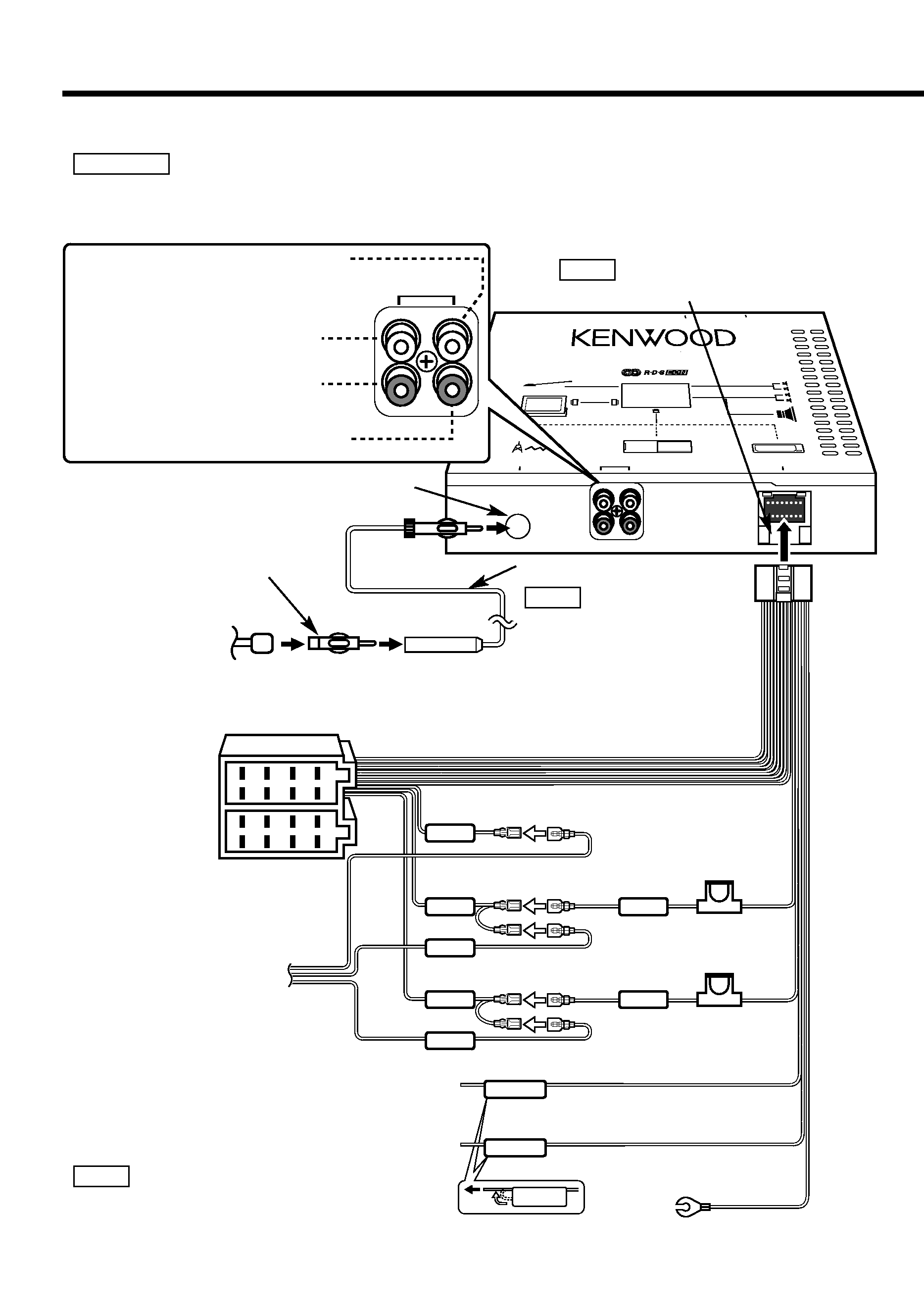
TO MZ-BUS
BATT
ACC
BATT
ACC
ILLUMI
P.CONT
TEL MUTE
FM·AM TUNER 44W
×4 AMPLIFIER
HIDEAWAY UNIT
KTC-1000R
ANTENNA INPUT
POWER
PREOUT
REAR/NON-FAD
FRONT
SUB WOOFER
REAR SPEAKER
FRONT SPEAKER
DAB
CHANGER
SLAVE UNIT
TV MONITOR
FM ANTENNA
TO 5L I/F
BATT
ACC
PREOUT
REAR/NON-FAD
FRONT
1
2
3
4
5
6
7
8
1
2
3
4
5
6
7
8
Installation
4 English
Wiring harness (5.5m) (Accessory5)
Rear left output (White) /
Non-fading left output (White)
Rear right output (Red) /
Non-fading right output (Red)
Front left output (White)
Front right output (Red)
FM/AM antenna input
Battery cable (Yellow)+12V
Ignition cable (Red)+12V
Automatic illumination control cable (Orange)
Ground cable (Black) -
(To car chassis)
Connect to the terminal that is grounded when either
the telephone rings or during conversation.
Power control cable (Blue/ White)
TEL mute cable (Brown)
To connect the KENWOOD navigation system,
consult your navigation manual.
NOTE
If you connect the ignition cable (red) and the battery cable (yellow) to the car chassis (ground), you
may cause a short circuit, that in turn may start a fire. Always connect those cables to the power
source running through the fuse box.
2WARNING
Antenna Cord (Accessory6)
Route wiring away from power
circuitry to avoid noise.
NOTE
Antenna Cord
(ISO)
Antenna Conversion
Adaptor (ISOJASO)
(Accessory8)
When using the optional power amplifier, connect to
its power control terminal.
Fuse
(10A)
Fuse
(3A)
Connecting Cables to Terminals
s
(5.5m)
Do not put anything into the fuse holder.
NOTE
Connector B
Connector A
Connect to control unit
power supply terminal.
If no connections are
made, do not let the cable
come out from the tab.
English
5
Connector Function Guide
Pin Numbers for
ISO Connectors
Cable Colour
Functions
External Power
Connector
A4
A5
A6
A7
Speaker
Connector
B1
B2
B3
B4
B5
B6
B7
B8
Yellow
Blue/White
Orange
Red
Purple
Purple/Black
Gray
Gray/Black
White
White/Black
Green
Green/Black
Battery
Power Control
Dimmer
Ignition (ACC)
Rear Right (
+)
Rear Right (
)
Front Right (
+)
Front Right (
)
Front Left (
+)
Front Left (
)
Rear Left (
+)
Rear Left (
)
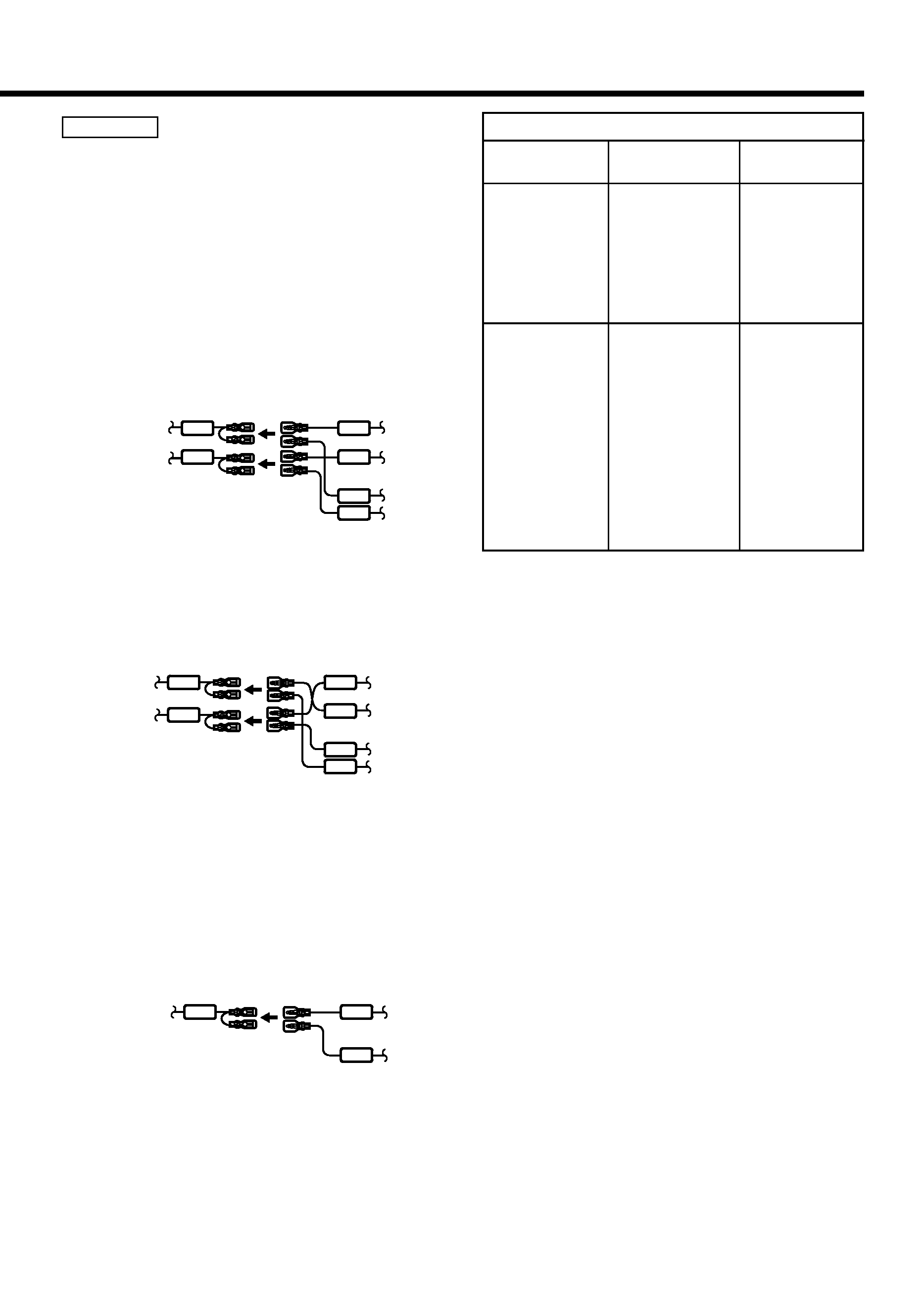
Connecting the ISO Connector
The pin arrangement for the ISO connectors
depends on the type of vehicle you drive. Make
sure to make the proper connections to
prevent damage to the unit.
The default connection for the wiring harness
is described in 1 below. If the ISO connector
pins are set as described in 2 or 3, make the
connection as illustrated.
2WARNING
BATT
ACC
BATT
ACC
BATT
ACC
Unit
Control
unit
Control
unit
Control
unit
Vehicle
Ignition cable (Red)
Battery cable (Yellow)
A7 Pin (Red)
A4 Pin (Yellow)
BATT
ACC
BATT
ACC
BATT
ACC
Unit
Vehicle
Ignition cable (Red)
Battery cable (Yellow)
A7 Pin (Red)
A4 Pin (Yellow)
Unit
Vehicle
Ignition cable
(Red)
Battery cable (Yellow)
A4 Pin (Yellow)
1 (Default setting) The A-7 pin (red) of the
vehicle's ISO connector is linked with the
ignition, and the A-4 pin (yellow) is
connected to the constant power supply.
2 The A-7 pin (red) of the vehicle's ISO
connector is connected to the constant
power supply, and the A-4 pin (yellow) is
linked to the ignition.
3 The A-7 pin (red) of the vehicle's ISO
connector is not connected to anything,
whilst the A-4 pin (yellow) is connected to
the constant power supply (or both the A-7
(red) and A-4 (yellow) pins are connected to
the constant power supply).
Connect to a power source
that can be turned on and
off with the ignition key.
BATT
BATT
BATT
|