
1
Chapter One : Connecting Your Devices
Audio-Video Receiver VR-3100/VR-3090/KRF-V9992D
Connections
Chapter One: Connecting Your Devices
Welcome to the Kenwood VR-3100/VR-3090/KRF-
V9992D Connection and Setup Guide. This chapter
guides you through connecting your home enter-
tainment devices to your new Kenwood audio-video
receiver.
Once all your devices are connected, you can set up
the PowerTouch (see Chapter Two).
Refer to the following pages for details on connect-
ing these devices:
Speakers
page 4
TV
page 8
VCR(s)
page 12
CD Player, Kenwood 200-Disc Changer
page 14
DVD Player
page 16
MD Recorder
page 18
Tape Deck(s)
page 18
Laser Disc Player
page 22
Turntable
page 26
Camcorder/Second VCR
page 27
Antennas
page 29
All necessary cables should be provided with your
home entertainment device (not with your new
receiver). If you do not have the correct cables, you
may purchase these cables from any home entertain-
ment store or by visiting the Kenwood USA Web
site: www.kenwoodusa.com (for USA and Canada
only).
To make coaxial digital connections, be sure to use a
high-quality digital audio cable, not a standard
audio cable.
Do not plug in the receiver or any other device to
AC power until all connections have been made.
Once all devices have been connected, you may plug
them in and provide power.
Important:
Your new receiver requires adequate ventilation to
perform reliably. Be sure not to block the ventilation
area on the top or back (or both sides) of the
receiver with another device. These areas should be:
USA and Canada: at least 6 inches (15 cm) from any
obstruction.
Other countries: at least top; 50cm, back; 10cm, and
left and right side; 10cm.
Do not install your receiver where direct sunlight or
high frequency flourescent lighting can shine
directly into the remote sensor. This can cause your
new receiver to malfunction.
Before You Begin
This manual covers the most common and standard
connections to the receiver. Because of its versatility,
you may decide to connect your devices differently.
Before making any video connections to the your
receiver:
·
You can use either S-Video or standard compos-
ite (RCA) video connections.
·
If all of your video devices and TV have S-Video
connectors, we suggest that you use them
exclusively, since it will provide superior video
performance.
·
If only some of your video devices and TV have
S-Video connectors, you can still use them for
those devices and the TV. Use the composite
connectors for your devices that don't have S-
Video connectors. In this case you'll also have to
connect the receiver's composite Video Monitor
output to your TV for your non S-Video devices
and switch between inputs on TV.
·
If your TV doesn't have S-Video connectors, you
can't use S-Video connections for any of your
video devices. Use the composite connectors
exclusively.
·
If your TV does not have any video connections
at all (it only has antenna connections), you
must purchase an RF modulator that converts
video signals into antenna signals to use it with
the VR-3100/VR-3090/KRF-V9992D. You should
be able to find an RF modulator at a store
specializing in electronic parts.
·
If you plan on using the VR-3100 in a Dual-Zone
application (see Chapter Three), you must use
the composite video connections in addition to
any S-Video connections. Only video sources
connected with composite connectors can be
viewed in the second zone.
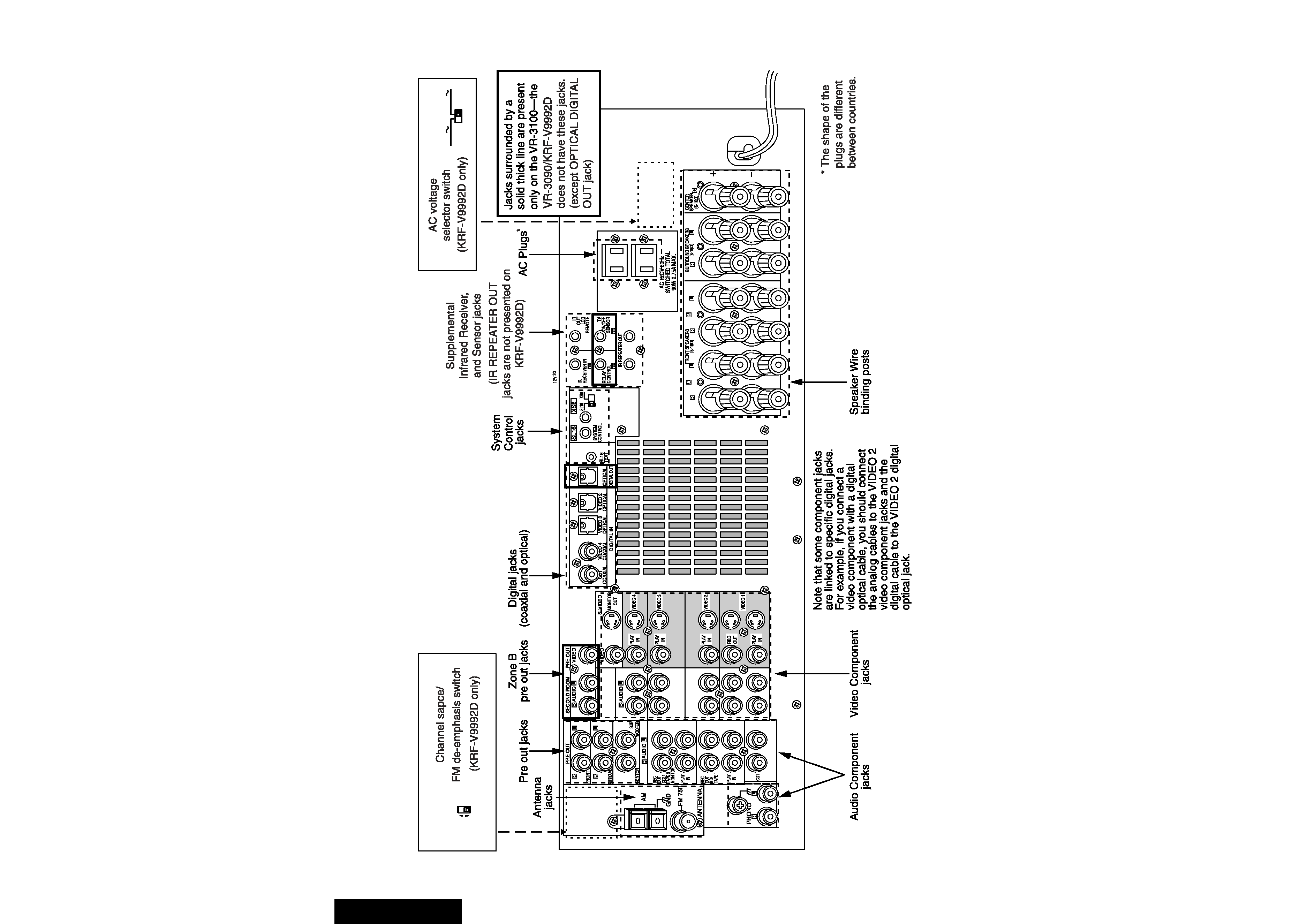
2
Chapter One : Connecting Your Devices
Audio-Video Receiver VR-3100/VR-3090/KRF-V9992D
Connections
The following diagram shows the entire back of the VR-3100/VR-3090/KRF-V9992D.
DE-
EMPHASIS
CHANNEL
SPACE
50
µs
AM 9kHz
FM 50kHz
75
µs
AM 10kHz
FM 100kHz
AC 110-
120V
AC 220-
240V
DC 12V
15mA
DC 12V
20mA
DC 5V
10mA

3
Chapter One : Connecting Your Devices
Audio-Video Receiver VR-3100/VR-3090/KRF-V9992D
Connections
Noting Your Devices
Use this table and the diagram on the preceding
page to plan your connections before you make
them, or use it to record your connections as you
make them. If you will be connecting a DVD player
or other device with a digital output, please refer to
the following chart before choosing a video jack set:
You will need this information later, when you set
up your PowerTouch (see "Identifying Devices For
PowerTouch Control" on page 35). Recording this
information now will save you additional trips
behind your home entertainment cabinet. You will
fill in the Setup Code column when you are setting
up PowerTouch.
Jack Set
Device
Manufacturer
Model #
Setup Code
Phono
CD1
MD/Tape1
CD2/Tape2 Monitor
Video1
Video2
Video3
Video4
Video
(TV1 on PowerTouch)
coaxial
VIDEO4
optical
VIDEO2 or 3
If your digital
cable is...
Choose this jack
set...
4
Chapter One : Connecting Your Devices
Audio-Video Receiver VR-3100/VR-3090/KRF-V9992D
Connections
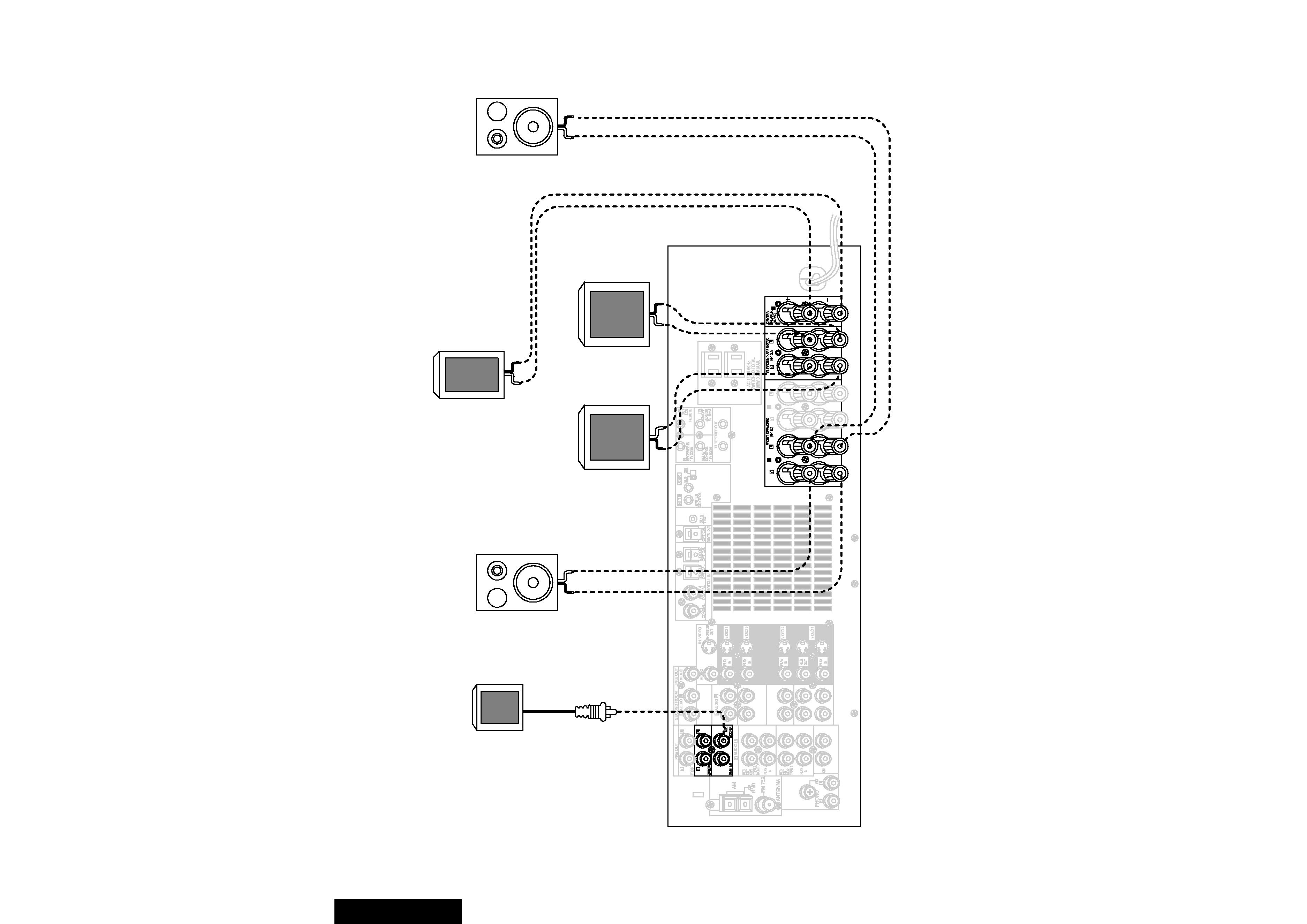
Connecting Your Speakers
A
B
C
POWERED
SUBWOOFER
R
FRONT
L
FRONT
CENTER
R
SURROUND
L
SURROUND
5
Chapter One : Connecting Your Devices
Audio-Video Receiver VR-3100/VR-3090/KRF-V9992D
Connections
Connecting Your Speakers, continued
Do not plug in the receiver to AC power until all
connections have been made.
To Connect Front Speakers Only:
If you only intend to listen to stereo sound (as
opposed to surround sound), you may simply
connect a single pair of speakers. To do so:
Using Banana Plugs:
1. Tighten the speaker wire binding posts. If you do
not tighten the posts, they will not conduct
sound properly to the speakers.
2. Insert the plug from the positive jack on the
RIGHT FRONT speaker into the pin jack on the
positive RIGHT FRONT post. Repeat for the
negative plug.
3. Repeat step 2 for the positive and negative wires
on the LEFT FRONT speaker.
Using Bare Wires:
1. Loosen the speaker wire binding posts.
2. Insert the wire from the positive jack on the
RIGHT FRONT speaker into the U-shaped slot in
the base of the positive RIGHT FRONT post. Lay
the wire to the right of the post; that way, when
you tighten the binding post, it will naturally
twist the wire into the best connection. Tighten
the post. Repeat for the negative wire on the
RIGHT FRONT speaker as shown to the right.
3. Repeat step 2 for the positive and negative wires
on the LEFT FRONT speaker.
To Connect Front and Surround Sound
Speakers:
To listen to the full surround sound that this
receiver can put out, connect front speakers, center,
left surround, and right surround speakers. To do so:
Using Banana Plugs:
1. Tighten the speaker wire binding posts. If you do
not tighten the posts, they will not conduct
sound properly to the speakers.
2. Follow the steps under "To Connect Front
Speakers Only" on this page to connect the
RIGHT and LEFT FRONT speakers.
3. Insert the plug from the positive jack on the
CENTER speaker into the pin jack on the positive
CENTER post. Repeat for the negative plug.
4. Insert the plug from the positive jack on the
RIGHT SURROUND speaker into the pin jack on
the positive RIGHT SURROUND post. Repeat for
the negative plug.
5. Repeat step 4 for the positive and negative wires
on the LEFT SURROUND speaker.
Using Bare Wires:
1. Loosen the speaker wire binding posts.
2. Follow the steps under "To Connect Front
Speakers Only" on this page to connect the
RIGHT and LEFT FRONT speakers.
3. Insert the wire from the positive jack on the
CENTER speaker into the U-shaped slot in the base
of the positive CENTER post, as shown to the right.
Tighten the post. Repeat for the negative wire.
4. Insert the wire from the positive jack on the
RIGHT SURROUND speaker into the U-shaped
slot on the base of the positive RIGHT SUR-
ROUND post. Tighten the post. Repeat for the
negative wire.
5. Repeat step 4 for the positive and negative wires
on the LEFT SURROUND speaker.
What if I Have a Powered Subwoofer?
Simply connect the subwoofer's audio cable to the
receiver's subwoofer PRE OUT jack as shown to the
left.
Never short circuit the + and - speaker wires.
Do not switch the left and right speaker wires or
swap the + and - wires on the binding posts.
The speakers must have a nominal impedance of
between 6
and 16.
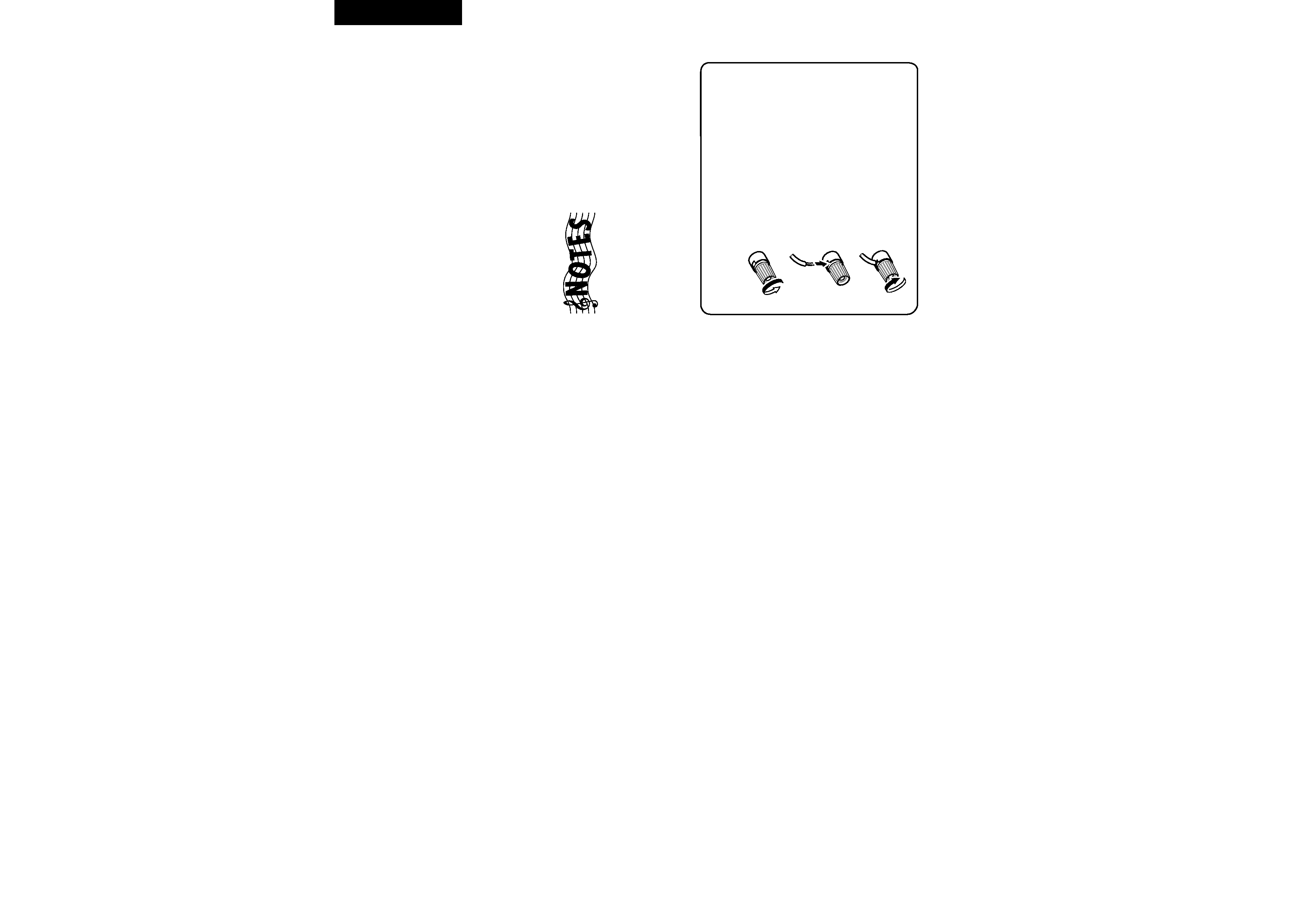
Using Speaker Wire
1. Loosen post
2. Insert wire
3. Tighten post