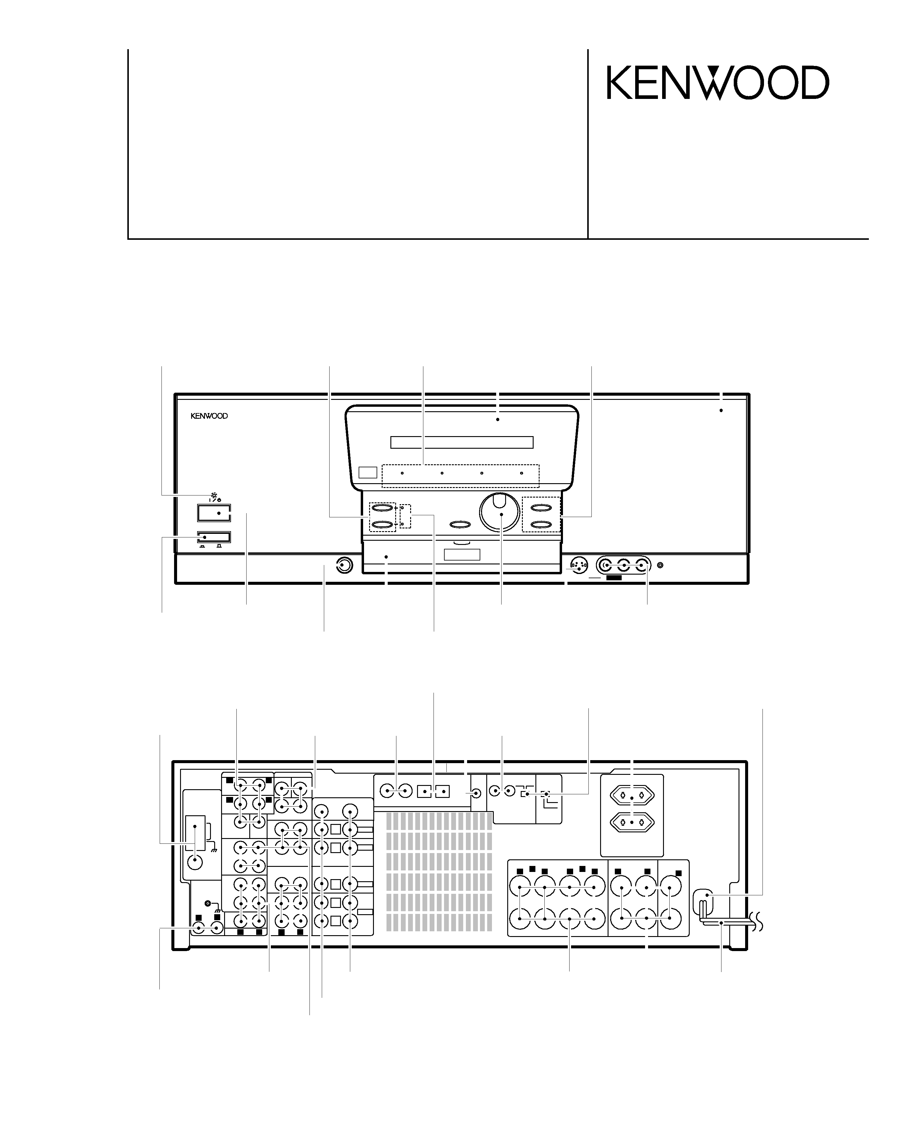
(E,T type)
AUDIO VIDEO SURROUND RECEIVER
KRF-V7771D/V7771DE
SERVICE MANUAL
© 1999-1/B51-5498-00 (K/K) 1612
PHONES
INPUT SELECTOR
VOLUME
MPEG
Cinema Re-EQ
DOLBY DIGITAL
CLIP INDICATOR
POWER
ON/STANDBY
A
B
SPEAKERS
MUTE
DOWN
UP
DISPLAY MODE
S VIDEO
VL-AUDIO-R
CD2 / TAPE2
MONITOR
ON
OFF
AV AUX
SYSTEM
CONTROL
FRONT SPEAKERS
(4-16
)
CENTER
SPEAKER
(4-16
)
SURROUND SPEAKERS
DIGITAL IN
VIDEO 2
COAXIAL
VIDEO 3
COAXIAL
VIDEO 4
OPTICAL
CD 1
OPTICAL
SL 16 XS 8
( SL 16 )( XS 8 )
(4-16
)
SWITCHED TOTAL
90W MAX.
L
R
A
L
R
L
C
R
B
SL 16
TEXT
L
R
R
ANTENNA
AM
-FM 75
GND
CD1
PHONO
MD/
TAPE 1
REC
OUT
PLAY
IN
REC
OUT
PLAY
IN
PLAY
IN
PLAY
IN
CD2 /
TAPE 2
MONITOR
MONITOR
OUT
FRONT
FRONT
SURROUND
SURROUND
CENTER
CENTER
SUB
WOOFER
SUBWOOFER
L
L
R
L
R
VIDEO
S VIDEO
PRE OUT
VIDEO4 6CH. INPUT
AUDIO
VIDEO 3
VIDEO 4
PLAY
IN
VIDEO 2
VIDEO 1
L
R AUDIO
PLAY
IN
REC
OUT
+
-
6CH
2CH
VIDEO 4
INPUT
Knob
(K27-2248-04)
AC power cord*
(E30-)
AC outlet*
(E03-)
Phono jack
(E63-1008-05)
Phono jack
(E63-1028-05)
Lock terminal board
(E70-0052-05)
Miniature Phone jack
(E11-0374-05)
Phono jack
(E63-1030-05)
Panel
(A60-1580-12)
Knob
(K29-6858-12)
Knob
(K29-6855-03)
Led holder
(J19-5876-04)
Knob
(K29-6855-03)
Knob
(K29-6852-04)
Phono jack
(E63-0200-05)
Phono jack
(E63-0136-15)x2
Phono jack
(E63-0139-15)x2
Slide switch
(S62-0034-05)
Front glass
(B10-2418-03)
Indicator
(B12-0326-04)
Front glass
(B10-3455-03)
Screw terminal board
(E70-0095-05)
Screw terminal board
(E70-0096-05)
*Refer to parts list on page52~.
This manual is available for repair in the Europe and England markets.
Please refer to the original manual (B51-5426-00) if need the information in the USA and Canada and other
markets.
Cylindrical receptacle
(E56-0011-05)x2
Phono jack
(E63-0162-05)x2
Power cord bushing
(J42-0083-05)
Miniature phone jack
(E11-0360-05)
Phono jack
(E63-1077-05)
Cylindrical receptacle
(E56-0012-05)
Phone jack
(E11-0271-05)
Indicator
(B12-0333-04)
Optical receiving module
(W02-1181-05)
KRF-V7771D/V7771DE
2
CONTENTS / ACCESSORIES / CAUTIONS
CONTENTS / ACCESSORIES / CAUTIONS ...............2
CONTROLS .................................................................3
DISASSEMBLY FOR REPAIR .....................................5
BLOCK DIAGRAM .......................................................6
CIRCUIT DESCRIPTION .............................................7
ADJUSTMENT .......................................................... 13
WIRING DIAGRAM ....................................................14
PC BOARD ................................................................15
SCHEMATIC DIAGRAM ............................................23
EXPLODED VIEW .....................................................51
PARTS LIST...............................................................52
SPECIFICATIONS .....................................................67
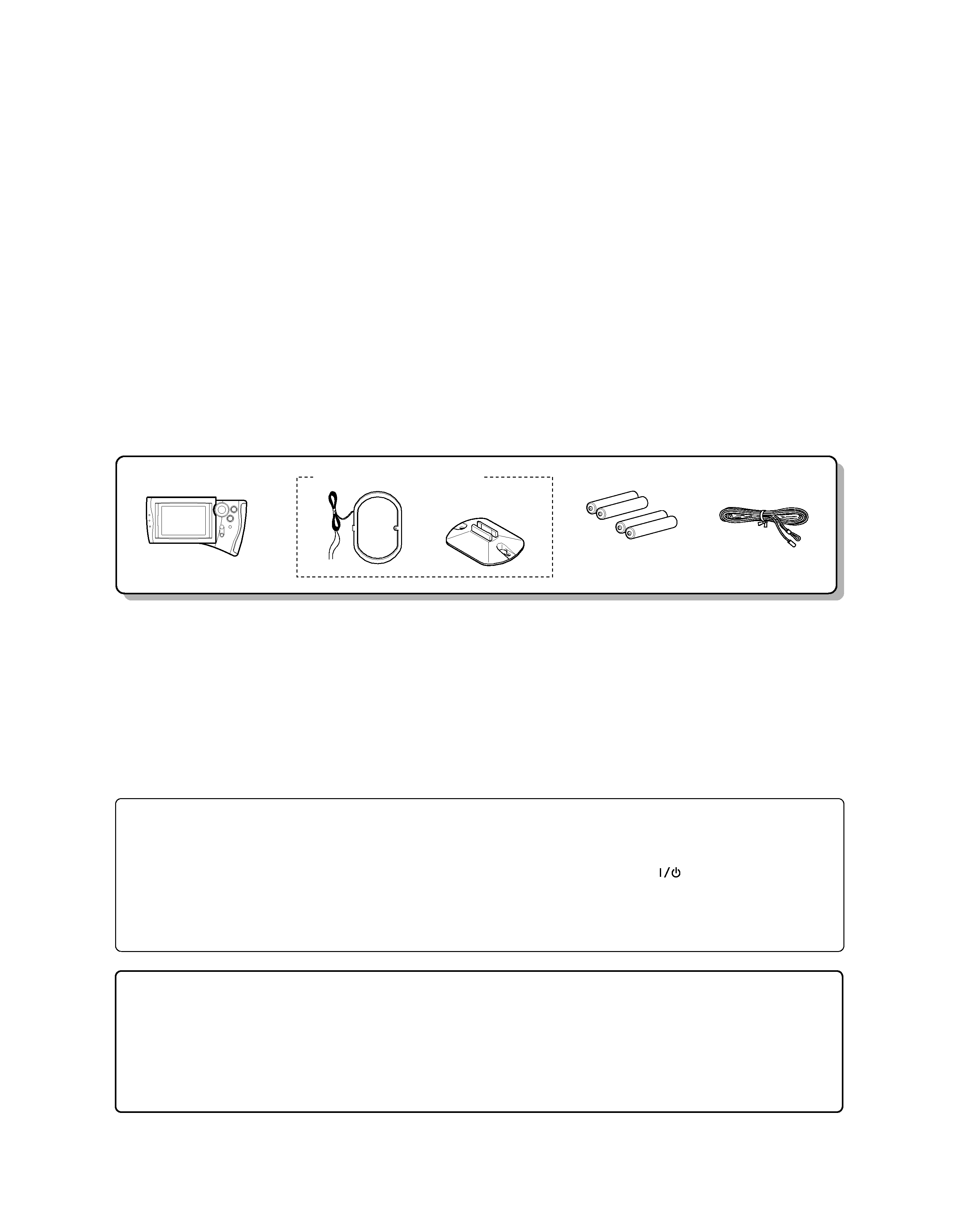
Contents
FM
(T90-0836-05)
indoor antenna (1)
Remote
(A70-1269-05)
(RC-R0807)
Battery cover(A09-1115-08)
control unit (1)
Loop antenna stand (1)
Batteries(R6/AA) (4)
AM loop antenna (1) (T90-0833-05)
(J19-3645-05)
How to reset the microcomputer
The microcomputer may malfunction (impossibility of operation,
erroneous display, etc.) when the power cord is unplugged and
plugged in again while the unit is in ON mode or due to other
external causes. In this case, execute the procedure on the right to
reset the microcomputer and return the unit to the normal condi-
tion.
÷ Resetting the microcomputer clears the memory you entered and
returns it to the initial condition when the unit left the factory.
1With the power cord plugged in, turn the POWER key to
OFF.
2While holding down the
(ON/STANDBY) key, press
the POWER key.
Please note that the following items will be deleted from
this unit's memory if the power cord is disconnected
from the AC outlet for approximately three days.
Memory backup function
÷ The frequency setting is cleared and 87.5 MHz is selected.
÷ The preset station memory is cleared.
÷ The surround setting is cleared and reset to the initial condition.
÷ The input selection is cleared and the "Tuner" input is selected.
÷ The volume setting is cleared and the volume is set to "-66 dB".
÷ The receiving band setting is cleared and the "FM" band is
selected.
Accessories
Cautions
KRF-V7771D/V7771DE
3
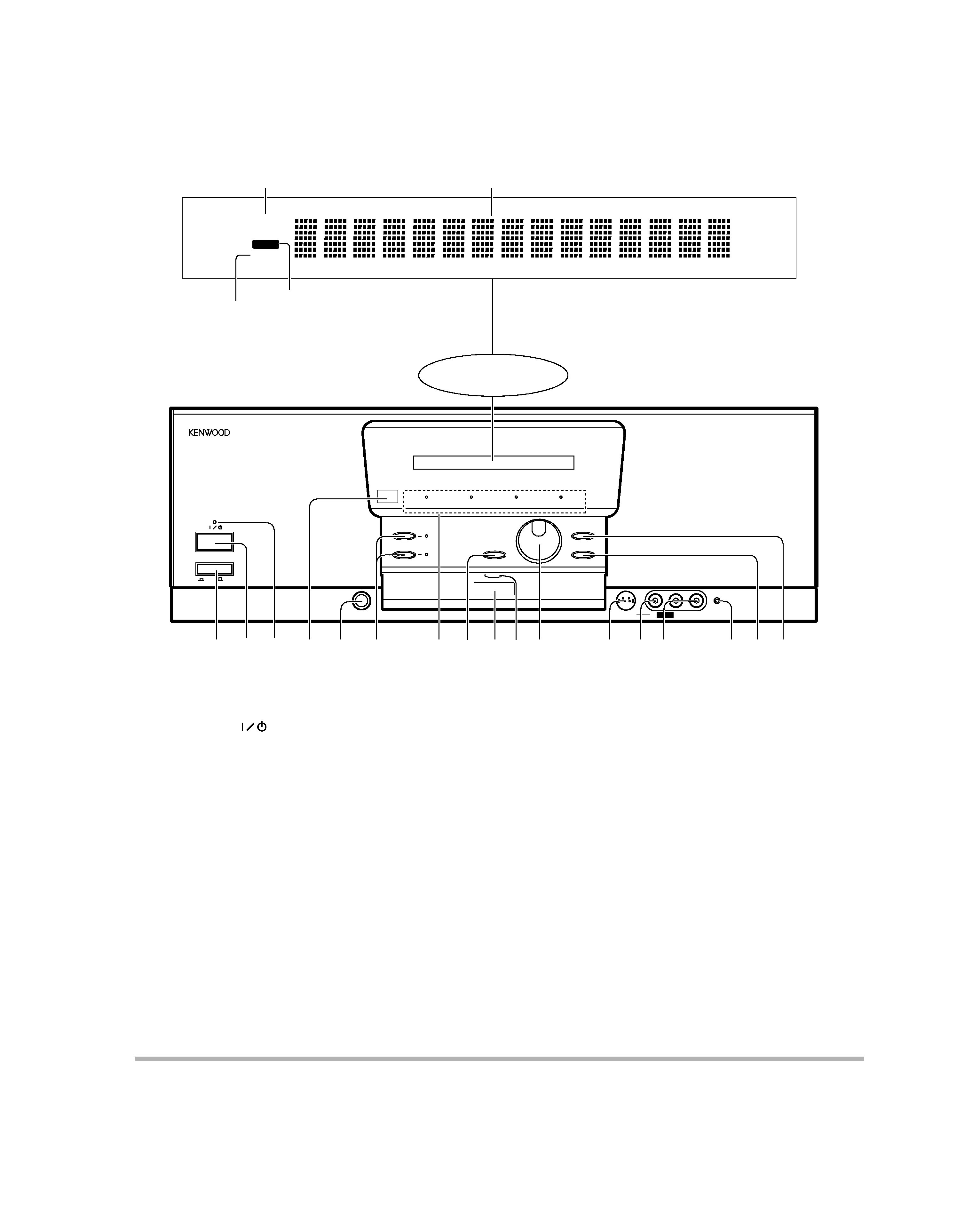
CONTROLS
PHONES
INPUT SELECTOR
VOLUME
MPEG
Cinema Re-EQ
DOLBY DIGITAL
CLIP INDICATOR
POWER
ON/STANDBY
A
B
SPEAKERS
MUTE
DOWN
UP
DISPLAY MODE
S VIDEO
VL-AUDIO-R
CD2 / TAPE2
MONITOR
ON
OFF
AV AUX
2 3
7
5
4
6
@ #
%
$
&
^
9
8
0
1
ST.
TUNED
MUTE
!
Standby mode
1POWER key
Press to switch the main power ON and OFF.
2ON/STANDBY (
)key
Press to switch the power mode between
STANDBY and ON.
3Standby indicator
Lights in standby mode.
4Remote sensor
Receives signals transmitted from the re-
mote control unit.
5PHONES jack
Use for listening to audio through headphones.
6SPEAKERS keys
Press each key to switch the SPEAKERS A or
SPEAKERS B ON and OFF.
7Indicators
CLIP INDICATOR :
Lights when the input is clipped during
analog to digital signal conversion.
DOLBY DIGITAL :
Lights when Dolby Digital is activated.
Stereo indicator
MUTE indicator
TUNED indicator
Multi-mode display
While the standby indicator of the unit is lit, a small amount of current is flowing into the unit's internal circuitry to back up the memory. This
condition is referred to as the standby mode of the unit. While the unit is in the standby mode, it can be turned ON from the remote control unit.
Display
MPEG :
Lights when the MPEG is activated.
Cinema Re-EQ :
Lights when the Re-EQ is activated.
8MUTE key
Press to mute the audio temporarily.
9Remote transmitter
Sends signals to the remote control unit.
0Communication indicator
Lights when signal is input from or output to
the remote control unit.
!VOLUME control knob
Rotate to adjust the volume.
@S VIDEO input jack (AV AUX)
Connect the S VIDEO output jack of an AV
component.
#VIDEO input jack (AV AUX)
Connect the composite video output (RCA)
jack of an AV component.
$AUDIO (L, R) input jacks (AV AUX)
Connect the audio output (RCA) jacks of an AV
component.
%CD2/TAPE2 MONITOR indicator
Lights when the CD2/Tape2 (Monitor) input is
used.
^DISPLAY MODE key
Press to switch the display on the receiver.
Press for more than 2 seconds to switch the
recording mode.
&INPUT SELECTOR key
Press to switch the input as shown below.
TUNER
CD1
MD/Tape1
VIDEO1
VIDEO2
VIDEO3
VIDEO4
AV AUX
PHONO
KRF-V7771D/V7771DE
4
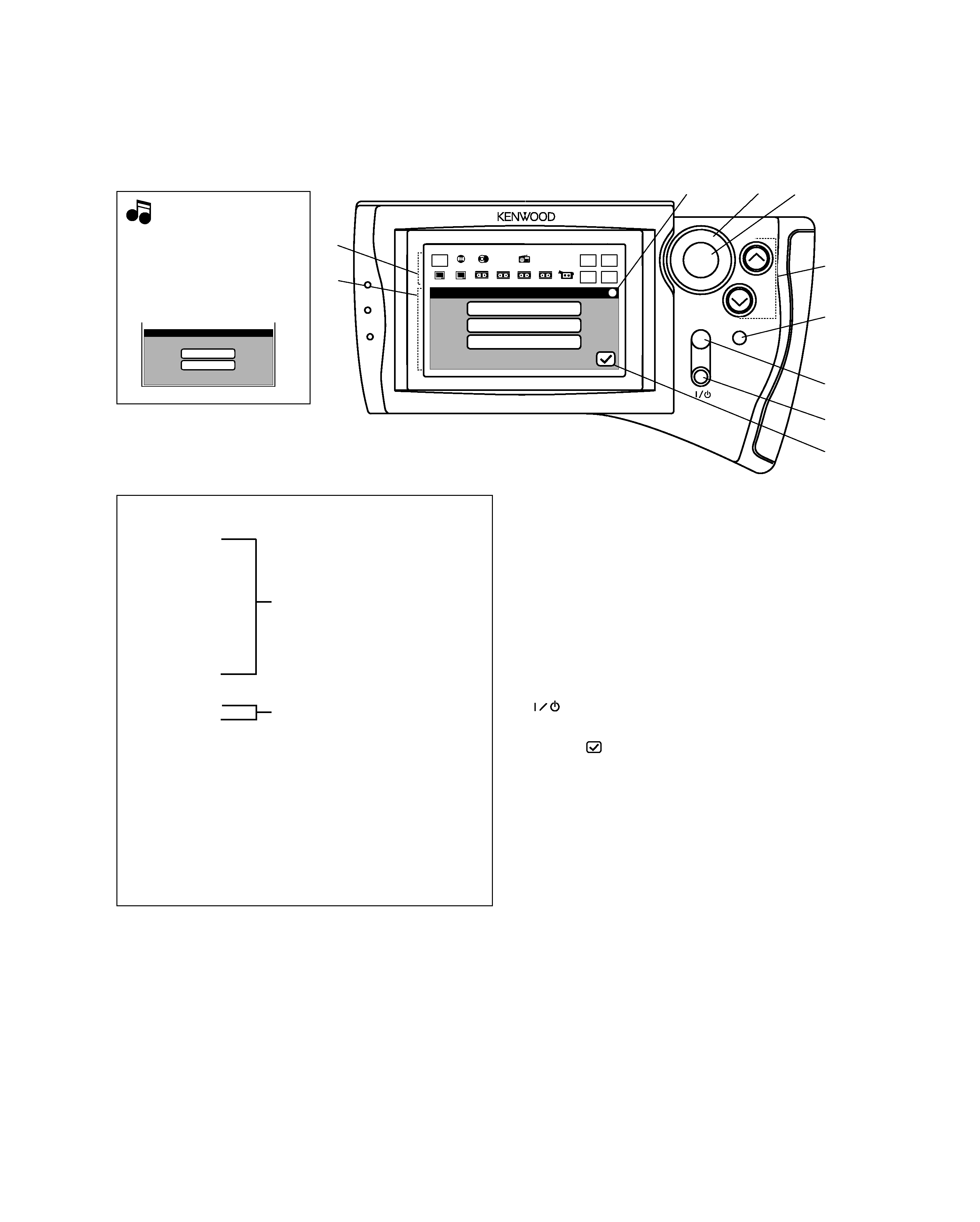
CONTROLS
Perform "Model Type Setup"
of the remote control before
using it.
The following menu display ap-
pears after the batteries are
loaded for the first time.
ON/STANDBY
MUTE
VOLUME
ENTER
Setup Surround
SP Level
SP Distance
SP Selection
Tuner
CD1
Video2
Video3
Video4
Video1
TV1
Phono
TV2
CD2
MD/
Tape1
CD2/
Tape2
Input
Digital
Input
Analog
AV AUX
Macro
Remote
Mode
Main
Menu
CONFIRM
1
2
3
45
6
7
8
9
0
Note
Note
1Segment screen
The fixed icons are displayed in this area.
÷ Main Menu icon : Select to display the Main Menu screen.
÷ Phono icon
÷ CD 1 icon
÷ Tuner icon
÷ MD/Tape 1 icon
÷ CD 2/Tape 2 icon
÷ Video 1 icon
÷ Video 2 icon
÷ Video 3 icon
÷ Video 4 icon
÷ AV AUX icon
÷ TV 1 icon
÷ TV 2 icon
÷ Macro icon : Select to control macro operation.
÷ Input Digital icon : Select to play a digital input.
÷ Input Analog icon : Select to play an analog input.
÷ Remote Mode icon : Select to switch the remote control operation
mode without changing the selected input.
Select to switch input and control the se-
lected input. ( Phono and AV AUX : Input
selection only )
Select to control TV.
2Menu screen
Control key icons and control levels are displayed in this area.
3Communication status display
Shows the communication status.
4Joy stick
This key is used to select an icon. This key can be controlled in
4 directions.
5ENTER key
Press to enter the selection of an icon.
6VOLUME (up, down) key
Press to control the volume.
7CONFIRM key
Press to confirm the currently selected items.
8MUTE key
Press to mute the audio temporarily.
9
(ON/STANDBY) key
Press to turn the receiver and the components connected to it
through system cords between ON and STANDBY modes.
0Return (
)icon
Select to return to the previous menu screen.
Model Type Setup
Model 2
Model 1
KRF-V7771D/V7771DE
5
DISASSEMBLY FOR REPAIR
6
6
3
4
4
9
9
3
3
2
11
12
1
4
3
5 x2
9 x5
8 x2
3 x2
7
13
13
13
14
14
15
10
1
2
2
2
1
x3
2 x3
2
2
x2
x5
2 x2
2
3
3
3
3
1
3
x29
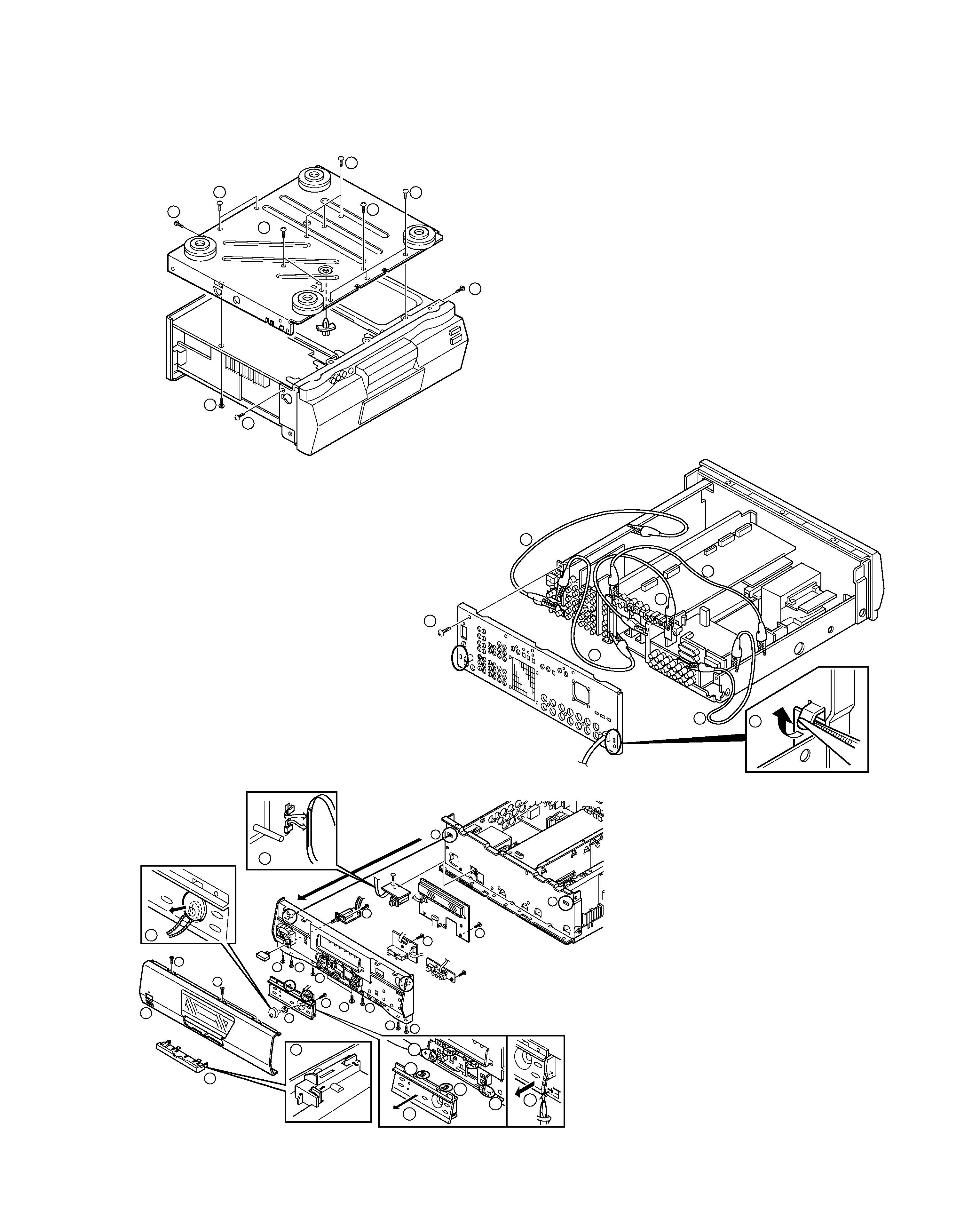
[Remove the bottom plate.]
Make use of the changing final transistor etc.
1. Remove the 19 screws (
1, 2) and PCB support, then
remove the bottom plate.
[Check the vertical PCB]
1. (Exist bottom plate) Remove the hook of rear
panel(
1).
2. Remove the 29(Exist bottom plate: 34)
screws(
2), then remove the rear panel.
3. Connect the GND of the phono terminal, the
GND of antenna shield board,the GND of
coax., the GND of system control shield
board, the GND of SP terminal shield board
and the chassis with 5 wires connected alli-
gator chips(
3).
[Remove the escutcheon (operation
panel)]
1. Remove the knob(
1), the nut (2), the 11
screws(
3, 4, 5) and 2 hooks (6), then
remove the front panel ass'y.
2. Remove the lead wire(
7), the 2 screws(8 :
except K,P type) and 7 screws(
9) then
remove the PCB.
3. Remove the under front glass(
0, -), then
remove the front panel(
=) from the sub
panel.
4. Remove the 2 under escutcheon sides(
~) by
· screw driver and the 2 hooks(!) then
remove the escutcheon(
@).
Fig. 3
Fig. 1
Fig. 2