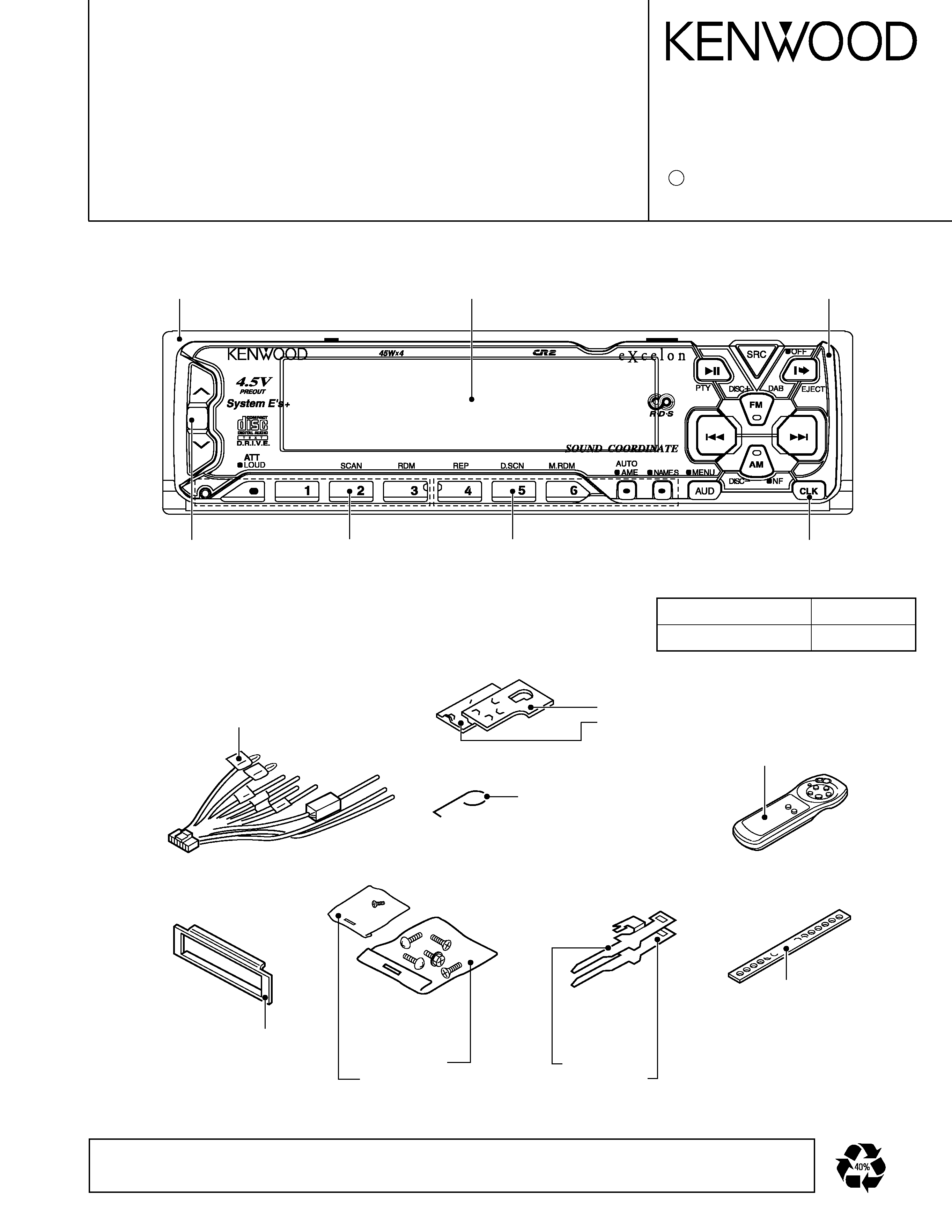
CD RECEIVER
KDC-X715
2000-1 PRINTED IN JAPAN
B51-7569-00 (4) 1469
SERVICE MANUAL
Extension cord
CD mechanism(22P)
Parts No.
W05-0618-00
THE MECHANISM OPERATION DESCRIPTION is the same as model KDC-S3007 and KDC-5050RG.
Please refer to the service manual for model KDC-S3007(B51-7029-00) or KDC-5050RG(B51-7099-00).
KDC-X715
DISP
DC cord
(E30-4779-05)
Torsion coil spring
(G01-2924-04)
Bracket
(J19-4875-04)
(J19-4876-04)
Remote controller assy
(A70-0894-05)
Escutcheon
(B07-2183-02)
Screw set
(N99-1652-05)
(N99-1683-05)
Lever
(D10-4301-14)
(D10-4302-14)
Stay
(J54-0606-04)
Escutcheon assy
(B07-2146-03)
Knob (VOL)
(K25-1095-03)
Knob (1-3)
(K25-1096-03)
Knob (4-6)
(K25-1097-03)
Knob (CLK)
(K25-1099-03)
Front glass
(B10-3110-01)
Panel assy
(A64-1870-02)
C
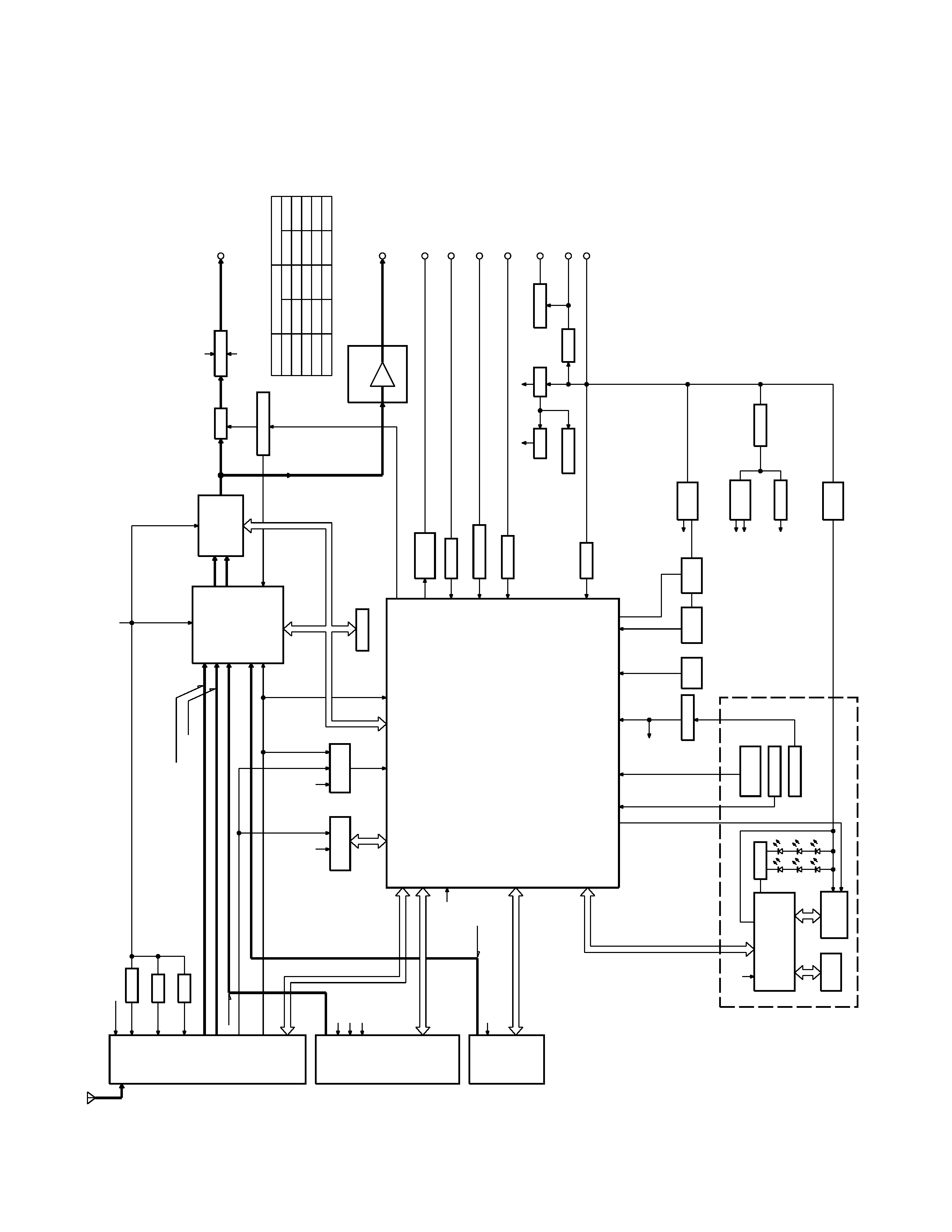
KDC-X715
BLOCK DIAGRAM
COM+B
FM+B
AM+B
E2PROM
DIMMER
2W
A
Y
MUTE
ACC
DET
.
SRM
PHOT
BU
DET
.
SRM
DRIVER
A8V
SER
VO
DC/DC
SW14V
SW5V
BU5V
P
CON
ANT
-CON
MUTE
DRIVER
4.5V
PRE
MUTE
E's
POWER
IC
IC4
IC14
u-com
IC1
CD
CH
IC10
IC7-9
IC5
IC2
F/E
MECHA
DET
.
E-VOL
PREOUT
SP-OUT
DIMMER
TEL-MUTE
ACC
ANT
-CONT
P-CON
BACK
UP
DECORDER
RDS
IC1
1
EX.AMP
CONTROL
AV
R
RESET
IC
IC15
ANT
.IN
AMP
IC12
NOISE
PREOUT
OUTPUT
VOL
T
AGE
CONTROL
EX.AMP
NA
VI-MUTE
P
ANEL
5V
4.5VPRE
IC3
IC6
ILLUM
+B
LCD
LCD
CONT
.1
G/R
SW
KEY
MA
TRIX
LCD
TYPE
LOCK
SW
P
ANEL
REMO
RESET
SW
PLL
CLK
CH
MO
SW
SER
VO+B
LO/EJ
ST
OP
MUTE
D
ATA
S
CLK
SW2
CS
SQR
D
ATA
M
SW3
SW1
A8V
BU5V
RST
REQ
C
CLK
CH-CON
D
ATA
H
REQ
H
CD
AM
FM
MUTE
RESET
SRMSW1
SRMDET
SRMSW2
RDCK
RDDA
QUAL
SDA
SCL
A8V
+B
-B
+B
-B
PLL
DA
T
A
PLL
CE
S-METER
SW5V
SW5V
D
ATA
C
BACK
UP
750mV
4500mV
CHANGER
AM
4.5V
PRE
2250mV
FM
160mV
1200mV
1200mV
213mV
(E
TYPE)
400mV
(K
TYPE)
RDS
OUT
FM+B
NOISE
4500mV
CD
K
TYPE
MODE
4500mV
4500mV
1069mV
1715mV
E
TYPE
3600mV
600mV
1800mV
3600mV
K
TYPE
E
TYPE
3600mV
1372mV
855mV
3600mV
1.8V
PRE
SRMSUB-
SRMSUB+
DRIVER
MUTE
BU5V
P
ANEL
5V
DIMMER
PWM
CONTROL
ILLUM
+B
IS
LCD
ONL
Y
RST
L
D
ATA
L
L
CLK
L
C
E
L
D
ATA
S
DIMMER
2

KDC-X715
MICROCOMPUTER'S DESCRIPTION
3
System
µ-com : UPD784217GC (X25-)
Terminal description
No.
Pin name
Function
I/O
Description
Processing Operation
1
2
3
4
5
6
7
8
9
10
11
12
13
14
15
16
17
18
19
20
21
22
23
24
25
26
27
28
29
30
31
32
33
34
35
36
37
38
39
40
41
42
43
44
45
46
47
48
49
P120/RTP0
P121/RTP1
P122/RTP2
P123/RTP3
P124/RTP4
P125/RTP5
P126/RTP6
P127/RTP7
Vdd
X2
X1
Vss
XT2
XT1
RESET
P00/INTP0
P01/INTP1
P02/INTP2/NMI
P03/INTP3
P04/INTP4
P05/INTP5
P06/INTP6
AVdd
AVref0
P10/ANI0
P11/ANI1
P12/ANI2
P13/ANI3
P14/ANI4
P15/ANI5
P16/ANI6
P17/ANI7
AVss
P130/ANO0
P131/ANO1
AVref1
P70/RxD2/SI2
P71/TxD2/SO2
P72/ASCK2/SCK2
P20/RxD1/SI1
P21/TxD1/SO1
P22/ASCK1/SCK1
P23/PCL
P24/BUZ
P25/SI0
P26/SO0
P27/SCK0
P80/A0
P81/A1
CHCON1
CH_MUTE
REQH
ILL_ON
NC
CD_SW2
CD_SW1
NC
Vdd
X2
X1
Vss
XT2
XT1
RESET
CH_RST
R_CLK
REQC
NC
NC
NC
SC_REQ
AVdd
AVref
PHONE
SRM_SW1
NOISE
SMETER
IF_MODE
NC
M_MUTE_R
M_MUTE_L
AVss
EXT_AMP
M_RST
DATAC
DATAH
CH_CLK
L_DATAL/SC_DATA
L_DATAS/MC_DATA
L_CLK/MC_CLK
M_STOP
BEEP
PLL_CE
PLL_DATA
PLL_CLK
CD_SW3
LO/EJ
O
I
O
O
O
I
I
O
-
-
-
-
-
-
I
O
I
I
I/O
I/O
I/O
I
-
-
I
I
I
I
I
I
I
I
-
O
O
-
I
O
I/O
I
I/O
I/O
O
O
O
I/O
O
I
O
Changer 1 control
Changer muting input
Handshake request to changers
Illumination output
Open
12cm DISC detection
Loading detection
Open
Positive power supply
Main clock connection
Main clock connection
GND
Sub clock connection
Sub clock connection
Reset input
Changer reset output
RDS clock input
Handshake request from changer
-
-
-
Handshake request from panel m-com
A/D analog power supply
A/D reference voltage input
PHONE detection terminal
SRM position detection
FM noise detection
FM signal meter detection
K2I IF selector
GND
Mute request from mechanism
Mute request from mechanism
A/D GND
EXT_AMP control
Reset output to mechanism
D/A reference voltage input
Data line from changer
Data line to changer
Clock line from/to changer
Data line from LCD driver
Data line to LCD driver
Clock line to LCD driver
Stop request to mechanism
Beep output
CE output to PLL
Data in/out with PLL
Clock output to PLL
Switch detection DOWN
Loading/Eject control
Active : Hi
MUTE Requested : Hi
Active : Lo
Active : Hi
ON : Lo
ON : Lo
Active : Lo
Active : Lo
Active : Lo
1V or less : PHONE
2.5V or more : NAVI MUTE
Open : Hi
Analog input
Analog input
Wide : Hi/Narrow : Lo
Mute requested : Lo
Mute requested : Lo
Reset : Lo
Stop Requested : Lo
Active : Hi
ON : Hi
Loading : Lo/Eject : Hi

KDC-X715
MICROCOMPUTER'S DESCRIPTION
No.
Pin name
Function
I/O
Description
Processing Operation
50
51
52
53
54
55
56
57
58
59
60
61
62
63
64
65
66
67
68
69
70
71
72
73
74
75
76
77
78
79
80
81
82
83
84
85
86
87
88
89
90
91
92
93
94
95
96
97
98
99
100
P82/A2
P83/A3
P84/A4
P85/A5
P86/A6
P87/A7
P40/AD0
P41/AD1
P42/AD2
P43/AD3
P44/AD4
P45/AD5
P46/AD6
P47/AD7
P50/A8
P51/A9
P52/A10
P53/A11
P54/A12
P55/A13
P56/A14
P57/A15
Vss
P60/A16
P61/A17
P62/A18
P63/A19
P64/RD
P65/WR
P66/WAIT
P67/ASTB
Vdd
P100/TI5/TO5
P101/TI6/TO6
P102/TI7/TO7
P103/TI8/TO8
P30/TO0
P31/TO1
P32/TO2
P33/TI1
P34/TI2
P35/TI00
P36/TI01
P37
TEST
P90
P91
P92
P93
P94
P95
MOSW
MECH_DET
PAN 5V
L_CE/P_RST
L_INH/MC_REQ
DIM_CON
QUAL
R_DATA
SRM_SUB-
SRM_SUB+
SRM_DET
SRM_SW2
FM_SD
NC
AFC
-
WIDE
NARROW
AM+B
FM+B
NC
NC
TYPE0
TYPE1
TYPE2
ST_TYPE0
ST_TYPE1
NC
PRE MUTE R
PRE MUTE L
NC
SVR
NC
P_MUTE
ANT_CON
IC2_SCK
DIMMER
P_CON
ACC_DET
REMO
P_ON
BU_DET
IC2_SDA
MUTE
SW5
MS_CL
MS_DA
-
O
I
O
O
O
O
I
I
O
O
I
I
I
O
O
O
O
I/O
O
O
O
O
-
I
I
I
I
I
O
O
O
-
O
O
O
O
O
O
I
O
I
I
O
I
-
I/O
O
O
O
I/O
O
Motor output
Mechanism detection
Panel detection
CE to LCD driver / Panel m-com reset
Reset to LCD driver
DIM control
RDS receiving condition
RDS data input
SRM sub motor output
SRM sub motor output
SRM mechanism detection
SRM eject detection
FM SD input
Open
Noise detection time constant switching
K2I Wide output
K2I Narrow output
AM power supply
FM power supply
Open
Open
GND
IC2 Var.3 destination type 0
IC2 Var.3 destination type 1
Open
Audio mute R
Audio mute L
Positive power supply
Open
Power IC reset
Open
Power IC muting
Antenna control
IC2,IC5,E2PROM clock line
Dimmer detection
Power control
ACC detection
Remote control input
µ-com peripheral power supply
Momentary power down detection
Test
IC2,IC5,E2PROM data line
Muting output
5V power supply
CD mechanism clock line
CD mechanism data line
NC
Loading Hi/Eject : Lo
ON : Hi/OFF : Lo
OFF : Hi
Good : Hi
ON : Lo/OFF : Hi
: Eject
Station detected : Hi
Not detected : Lo
During reception : Hi
During search : Lo
Active : Hi
Active : Hi
Active : Hi
Active : Hi
Destination type switch
Destination type switch
Destination type switch
Initial value : Lo
Initial value : Lo
Active : Lo
Active : Lo
Power ON : Lo
Active : Lo
Active : Hi
Active : Lo
Active : Hi
ACC OFF : Hi
Active : Hi
Momentary power down : Hi
GND
Active : Hi
Active : Lo
4

KDC-X715
TEST MODE
1. Entering the test mode
Reset the unit by pressing the FM key and the Preset 6
key at the same time.
When the test mode is entered, all indicators light up.
2. Releasing the test mode
Reset the unit by pressing the preset 6 key.
Note: The unit cannot be reset by simply turning ACC off,
turning power off, or turning power off for a brief moment.
3. Voltage adjustment on the FM S-meter
(1) Enter the test mode.
(2) While pressing the Preset 1 key, keep on pressing the
Preset 6 key.
(3) When the adjustment is made, "ADJ OK" is displayed.
When adjustment cannot be mede, "ADJ NG" is dis-
played.
4. Writing SD voltage for the AM
(1) Enter the test mode.
(2) While pressing the Preset 1 key, keep on pressing the
Preset 6 key, which results in writing SD.
5. Forced switching of K2I Auto/Manual
In tuner-mode, keeping on pressing TI key, and the Auto
and Manual modes can be switched. The initial condition
is in manual modes, which is indicated by flashing DUAL
dots.
6. Forced narrow/wide switching of K2I
In tuner-mode,when Preset 6 is pressed, forced narrow/
wide mode switching is made. The initial condition is in
wide mode and the NEWS dot flashes.
7. CD receiver test mode specification
By pressing the track-up key, the unit jumps to the follow-
ing tracks:
No.9
No.15
No.10
No.11
No.12
No.13
No.14
No.9 (Goes back to the first position.)
When the track-down key is pressed, the unit jumps to the
previous track.
8. MD test mode specification
After loading MD, the unit plays No.7. Then,the unit jumps
as follows each time it trackups.
No.2
No.13
No.23
No.30
No.34
No.7
(Goes back to the first position.)
When the track-down key is pressed, the unit jumps to the
previous track.
9. Tape test mode
In the initial step,the blank skip is turned off.
10. Audio-related items
· The volume is -10dB (on display, it is 30).
· The loudness is off and CRSC is off regardlles of func-
tions.
· Buss/treble and balance/fader are to be adjusted by the
up/down key to full-boost/fullcut and fullfront/fullrear
respectively.
·The high-pass filter is adjusted by the up-key to through-
put/100Hz/200Hz and, by the down-key,to 200Hz/
100Hz/ throughput.
· Other adjustments are the same sa before.
11. Backup current measurement
When reset in ACC-off condition (backup is on), the mute
terminal goes off after 2 seconds instead of 15 seconds,
when the ACC is turned off in the test mode. (In this case,
the panel/CD/C/MD mechanisms are not activated.)
12. Registering security code after changing E2PROM
at the services (Only for type M. However, RDS
models are excluded.)
(1) Put the unit into the test mode (Refer to 1. Above for
how to enter the test mode.)
(2) Press SRC key to put the unit into the tuner mode.
(3) Press Audio key for one second and put the unit into
the menu mode.
(4) Press FM/AM key and then select "SECURITY."
(5) Press track up/down key for full 2 seconds.
(6) Press Preset 1, Preset 2, Preset 3, and Preset 4 and
then input codes.
Example: Inputting "3510."
· Press 1 key 4 times.
· Press 2 key 6 times.
· Press 3 key 2 times.
· Press 4 key once.
(7) Press DISP key for 3 seconds and confirm that
"APPRODVED" is displayed.
(8) Release the test mode. (Refer to "2. Releasing the test
mode" above.)
5