KCA-S220A
©PRINTED IN JAPAN B64-3452-00/00 (W)
CD / MD CHANGER SWITCHING UNIT WITH AUXILIARY RCA
STEREO INPUT
3 page 2-5
INSTRUCTION MANUAL
UNITE DE COMMUTAION DU CHANGEUR CD/MD AVEC ENREE
STEREO RCA AUXILIAIRE
3 page 6-9
MODE D'EMPLOI
CD-/MD-WECHSLER-SCHALTGERÄT MIT ZUSÄTZLICHEM RCA-
STEREO-EINGANG
3 Seite 10-13
BEDIENUNGSANLEITUNG
SCHAKELEENHEID VOOR DE CD / MD WISSELAAR MET EXTRA
CINCH STEREO INGANG
3 biz. 14-17
GEBRUIKSAANWIJZING
UNITÀ DI COMMUTAZIONE DEL MULTILETTORE CD / MD CON
INGRESSO STEREO RCA AUSILIARIO
3 pagina. 18-21
ISTRUZIONI PER L'USO
UNIDAD CAMBIADORA DE CAMBIADORES CDs/MDs CON
ENTRADA AUXILIAR ESTÉREO RCA
3 página 22-25
MANUAL DE INSTRUCCIONES
UNIDADE DE COMUTAÇÃO DO CARREGADOR CD / MD COM
ENTRADA AUXILIAR RCA ESTÉREO
3página 26-29
MANUAL DE INSTRUÇÕES
2
KCA-S220A
Connection
Connectable Control Units and Disc Changer/Disc Player Units
7 Connectable Control Unit
Group A: This group covers control units with disc changer control, where the source selection allows you
to switch between 1 and 2, where the manual instructs you to set the O-N switch on the disc
changer to "N".
Group B: This group covers units released on to the market in or after 1999, where the manual covers AUX
mode under switching sources.
7 Connectable Disc Changer/Disc Player Units
Disc changer/disk player units released on to the market in or after 1999.
· Any control unit and disc changer/disc player unit other than those above cannot be connected. If connected, the
switching unit can be out of order or damaged.
· If the disc changer/disc player unit you have connected has an O-N switch, set it to the "N" position.
Components
! Switching unit..................................................1
# Velcro strip..........................................................2
" Connection cable (2 m)..............................1
$ Self-tapping screw ( 4 × 16 mm).......2
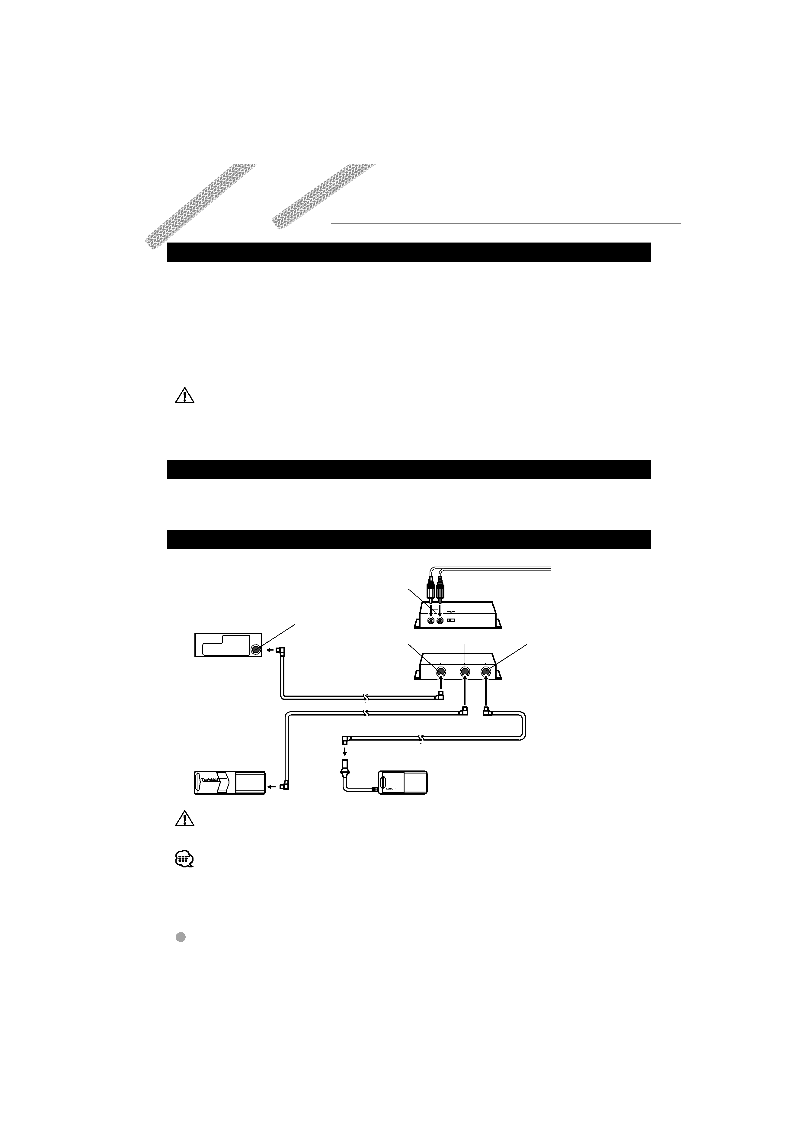
Connection Example
TO CHANGER 2
TO CHANGER 1
TO HEAD UNIT
SWITCH
AUX
OFF
ON
IN
AUX
To the external unit
TO CHANGER 2
TO HEAD UNIT
AUX IN
Connection cable (supplied with the CD changer)
Connection cable (supplied with the MD changer)
MD Changer
CD changer
Control unit
Switching unit
!
(Rear side)
Switching unit
!
(Front side)
Changer control output
Connection cable
"
TO CHANGER 1
· After connecting the equipment, press the reset button on the control unit.
· The figure shows that one CD changer and one MD changer are connected. Two CD changers or two MD changers may be
connected.
· A disc player such as the KDC-D301 or KCA-iP500 (etc.) may be connected instead of the disc changer.
· If you wish to adjust the cable length in accordance with the installation location of the switching unit, such as in the trunk
space, the disc changer extension cable may be used instead of the connection cable
".
· When a control unit belonging to Group A is used, you cannot use both TO CHANGER 2 terminal and AUX terminals at the
same time. For more details, see <Setting the AUX Switch> (page 5).
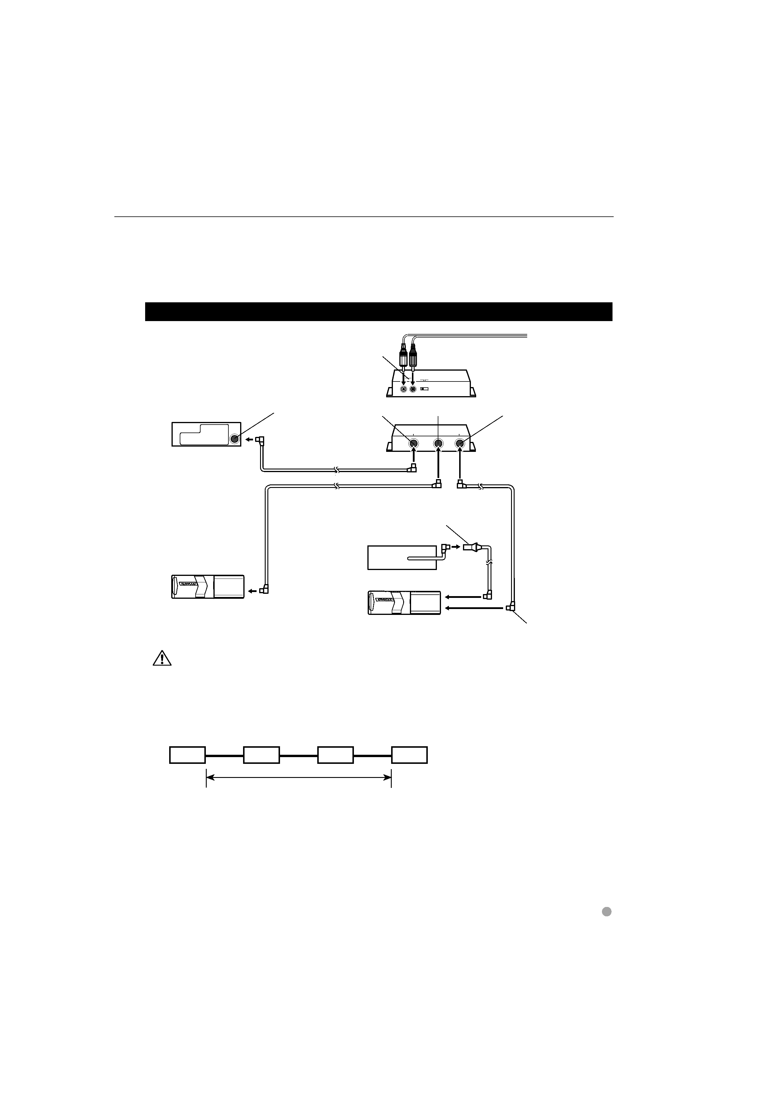
If you want to connect a stack CD changer
TO CHANGER 2
TO CHANGER 1
TO HEAD UNIT
SWITCH
AUX
OFF
ON
IN
AUX
To the external unit
Connection cable (supplied with the Disc changer)
Extension cable (CA-C2EX: Optional)
Stack CD changer
Disc changer
Control unit
Connection cable
"
Switching unit
!
(Rear side)
Switching unit
!
(Front side)
Disc player
Connection cable (supplied with the stack CD changer)
TO HEAD UNIT
Changer control output
AUX IN
TO CHANGER 1
TO CHANGER 2
· Connect the stack CD changer to the terminal labelled TO CHANGER 2.
· Up to two disc changers can be connected.
· The O-N switch on the disc changer and the disc player should be set to "N". If you set it to "O", the equipment will not
function correctly.
· The total length of the cable between the units should not be more than 13 m (43 ft).
Control unit
KCA-S220A
Stack CD Changer
Disc Player
Not more than 13 m (43 ft)
· If the voltage is low and the internal temperature of the switching unit is low, switching may fail to work properly in some
cases.
· The AUX switch on the stack CD changer should be switched "OFF" before using the equipment. The AUX terminal on the
KCA-S220A switching unit is the one that should be used.
English
3
4
KCA-S220A
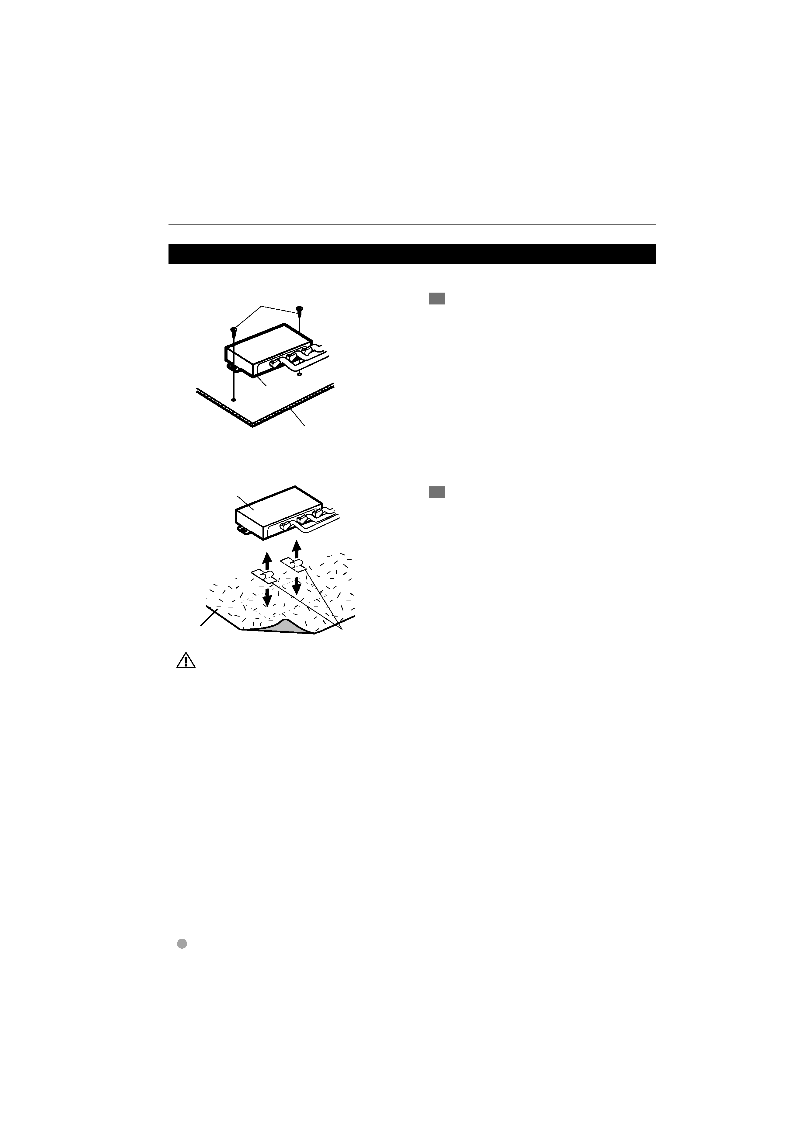
7 Installing the switching unit on the carpet under a seat
· Velcro strips are used to install the switching unit in a simple manner. To install the switching unit securely, use of self-
tapping screws is recommended.
· Install the switching unit ! in places that do not obstruct driving.
· Install the switching unit ! in places where it is not touched by the tip of the shoes of a rear seat passenger.
Route cables so that they are not caught in slide rails.
· Do not install the unit in places where it is exposed to direct sunlight, high heat, or where water may splash over it.
· Do not place anything on top of the switching unit !.
Installation
7 Installing the switching unit with a board in the trunk space
Connection
Self-tapping screw
$
(
4 × 16 mm)
Switching unit
!
Board etc.
thickness: 17mm or more
1 Install the switching unit with self-tapping
screws
$ ( 4 × 16 mm).
Switching unit
!
Velcro strips
#
carpet
1 Remove the backing from the velcro strips #
and attach it to the bottom of the switching
unit
!. Install the switching unit on the
carpet.
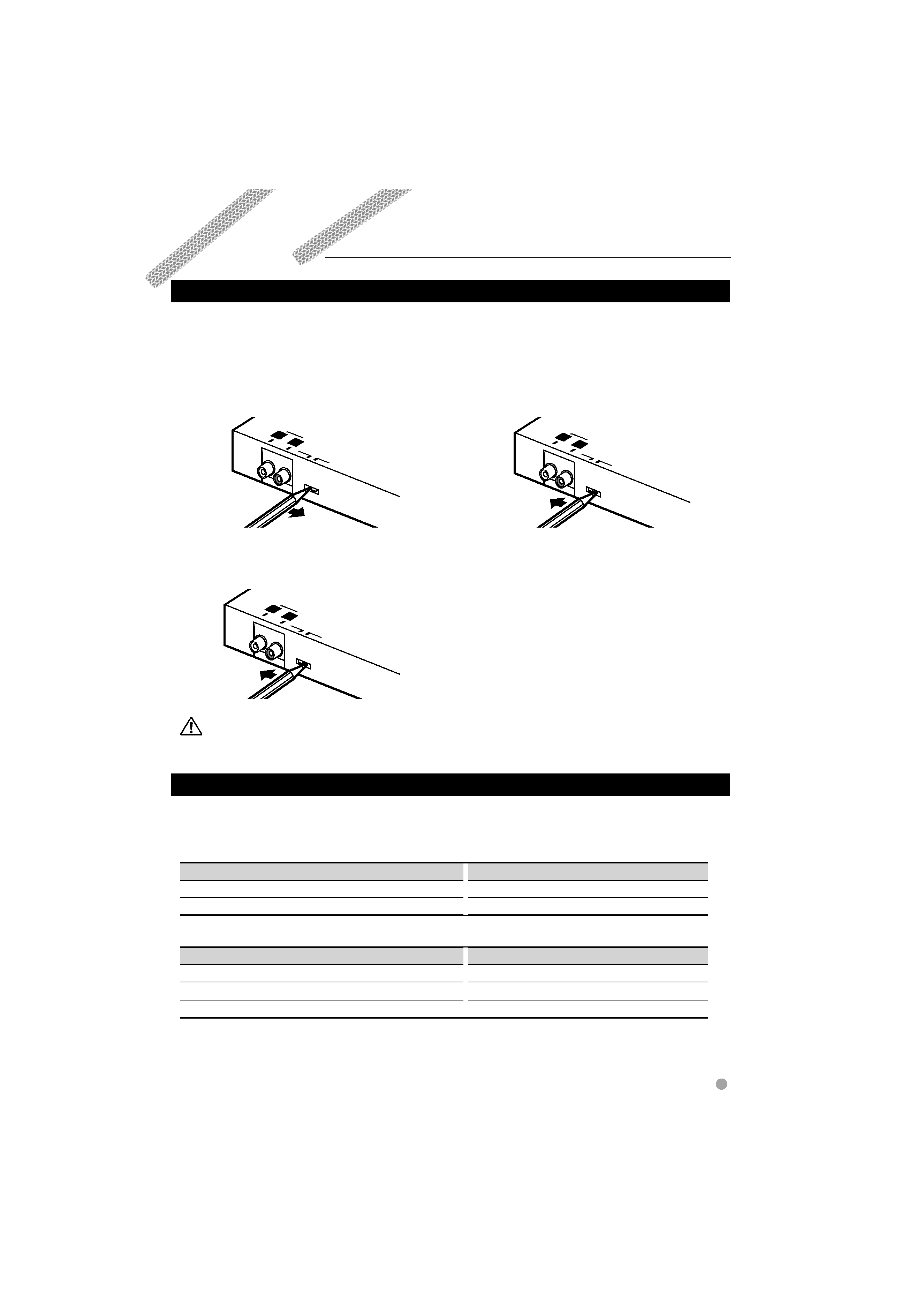
Setting Method
Setting the AUX Switch
Set the AUX switch.
7 Setting the AUX switch of the switching unit belonging to Group A
7 Setting the AUX switch of the switching unit belonging to Group B
Set the switching unit AUX switch to "ON".
AUX
SWITCH
OFF
ON
AUX
IN
L
R
· Before setting the AUX switch, be sure to turn off the control unit.
Switching Sources
Each time the SRC button on the control unit is pressed, the source changes. For details on how to change
sources, refer to the instruction manual that comes with the control unit.
7 If the unit you are connecting belongs to Group A
Source to Change
Source Selected by Control Unit
Unit connected to TO CHANGER 1 terminal
Disc Changer 1
Unit connected to TO CHANGER 2 or AUX terminal
Disc Changer 2
7 If the unit you are connecting belongs to Group B
Source to Change
Source Selected by Control Unit
Unit connected to TO CHANGER 1 terminal
Disc Changer 1
Unit connected to TO CHANGER 2 terminal
Disc Changer 2
Unit connected to AUX terminal
AUX / AUX EXT
English
5
¶ To listen to the sound of the unit connected
to the TO CHANGER 1 and TO CHANGER 2
terminals
Set the switching unit AUX switch to "OFF".
AUX
IN
AUX
SW
ITCH
OFF
ON
L
R
¶ To listen to the sound of the unit connected
to the TO CHANGER 1 and AUX terminals
Set the switching unit AUX switch to "ON".
AUX
SWITCH
OFF
ON
AUX
IN
L
R