70%
PORTABLE CD PLAYER
DPC-MP727/MP922
SERVICE MANUAL
© 2001-3/B51-5706-00 (K/K) 3360
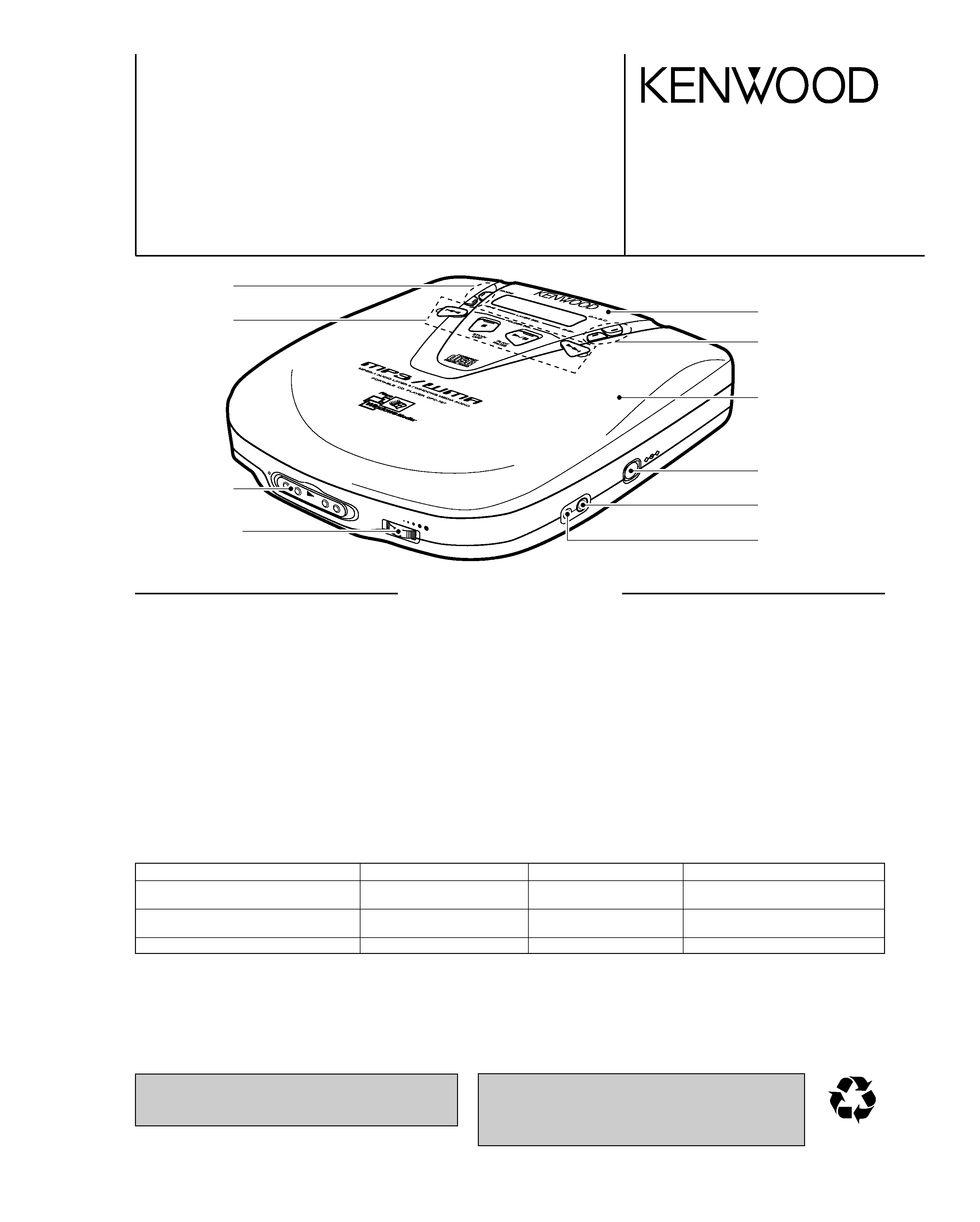
OPE
N
_
+
DC
IN
PHONES/LINE
O
UT
REMOTE
VOLUME
HO
LD
Knob
(K29-7957-04)
Cover *
(F07-)
DC jack
(E03-0342-05)
Miniature phone jack
(E11-0933-05)
Miniature phone jack *
(E11-0932-05)
Variable resistor
(R31-0056-05)
Knob
(K29-7954-14)
Knob
(K29-7955-03)
Knob
(K29-7956-04)
Front glass
(B10-3675-03)
In compliance with Federal Regulations, following are
repro-duction of labels on, or inside the porduct relating to
laser product safety.
KENWOOD-Crop. certifies this equipment conforms to DHHS
Regulations No.21 CFR 1040. 10, Chapter 1, Subchapter J.
DANGER : Laser radiation when open and interlock defeated.
AVOID DIRECT EXPOSURE TO BEAM.
SPECIFICATIONS
Standards
Signal reading format .......................................................................................Non-contact signal reading (semi-conductor laser)
Characteristics
Frequency characteristics ..............................................................................................................................20Hz to 20kHz, ±3dB
Headphone output (16
, 1kHz) .................................................................................................................................9mW + 9mW
LINE OUT output level/impedance .......................................................................................................................MAX 0.85V/10k
Power supply
External DC supply ...................................................................................................................................................DC 4.5 to 5.1V
Size AA alkaline batteries available on the open market (LR6/AA x 2 or 4) ..........................................................................DC 3V
Rechargeable batteries (NB-150 x 2) .................................................................................................................................DC 2.4V
Maximum external dimensions (width x height x depth) ........................................................................129mm x 32mm x 138mm
(5-1/16x 1-1/4 x 5-7/16)
Weight (net) ..................................................................................................................................................................260g (0.6lb)
Battery life expectancy (during continual repeated playback)
The standard accessories vary depending on the model of the unit.
The accessories which are not standard are optionally available. For details, please consult your dealer.
Note:
KENWOOD follows a policy of continuous advancements in development. For this reason specifications may be changed without
notice.
Battery
When D.A.S.C. is off
When D.A.S.C. is on
During MP3/WMA file playback
Size AA alkaline batteries available
Approximately
Approximately
Approximately
on the open market (LR6/AA x 2)
9 hours
10 hours
10 hours
Size AA alkaline batteries available
Approximately
Approximately
Approximately
on the open market (LR6/AA x 4)
18 hours
22 hours
22 hours
Rechargeable battery (NB-150 x 2)
Approximately 7 hours
Approximately 8 hours
Approximately 8 hours
* Refer to parts list on page 15.
DPC-MP727/MP922
2
CONTENTS / ACCESSORIES / CAUTIONS
SPECIFICATIONS ............................................Cover
CONTENTS / ACCESSORIES / CAUTIONS........... 2
CIRCUIT DESCRIPTION ..........................................3
TEST MODE .............................................................6
ADJUSTMENT ..........................................................7
PC BOARD .............................................................. 8
SCHEMATIC DIAGRAM ........................................ 10
EXPLODED VIEW ..................................................14
PARTS LIST ...........................................................15
Contents
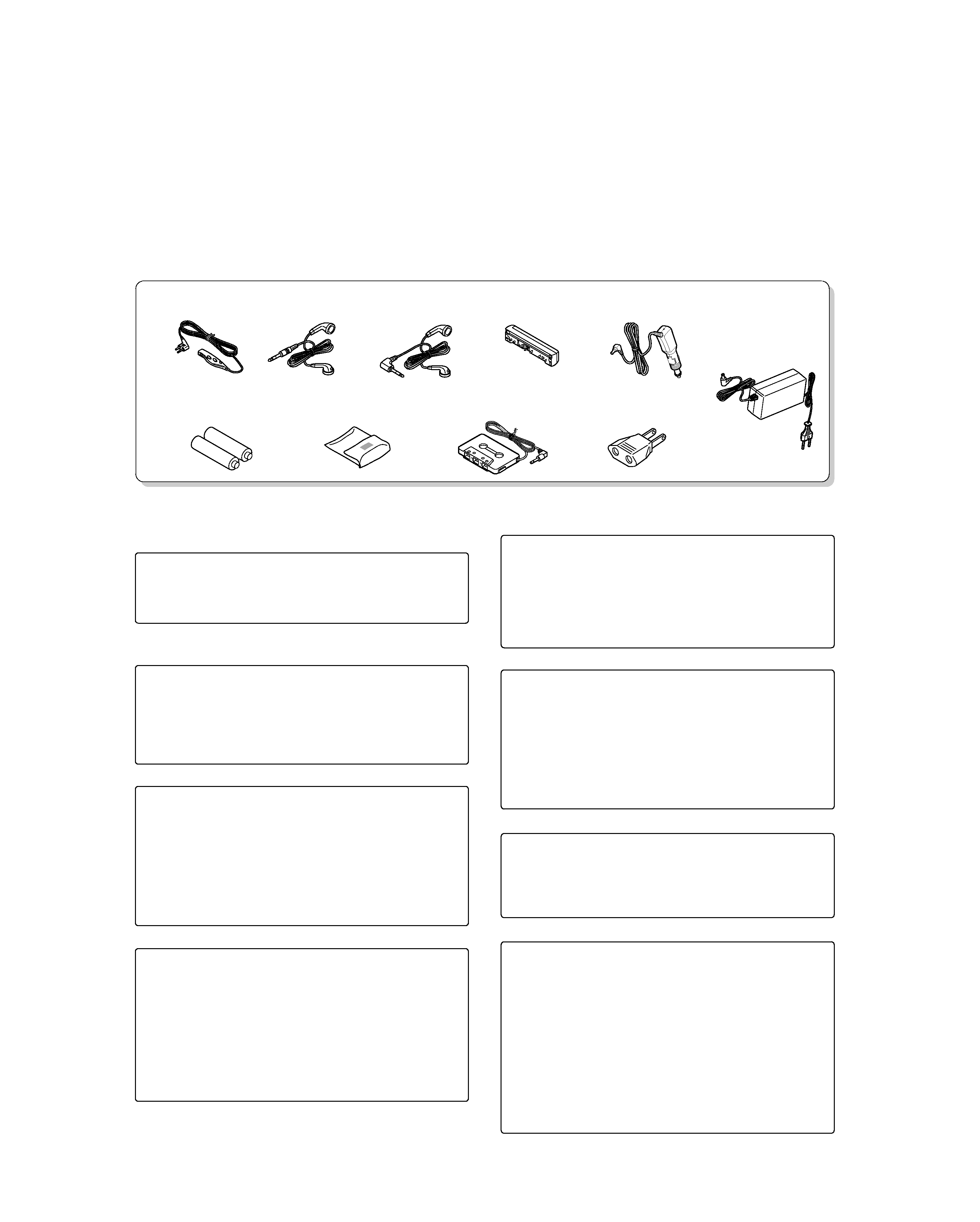
Accessories
Cautions
Media that can be played back with this
equipment
Usable media apart from audio CDs (CD-DA)
Usable media
: CD-ROM, CD-R, CD-RW
Usable formats
: ISO9660 level 1 and level 2
(excluding expanded formats)
Files that can be played back: MP3 and WMA files
Creating media for playing back on this
equipment
Compressing MP3 and WMA files
Please set up the transfer bit rate setting for the compression
software when compressing MP3 and WMA files as follows:
MP3 Files
: 128kbps recommended (32kbps-320kbps)
WMA Files
: 128kbps recommended (64kbps-160kbps)
¶ This unit is compatible with 32kHz, 44.1kHz (recommended)
and 48kHz sampling frequencies.
Categorizing folders
As MP3 and WMA files are compressed into high-quality sound
files at an extremely high rate of compression, it is possible to
record several times more tracks than audio CDs onto a single
medium. It is therefore convenient to split the tracks into differ-
ent folders by genre, artist or album for retrieval and repeat play-
back purposes.
¶ A maximum of 23 folders or a maximum of 200 files can be
stored on a single media.
¶ There are cases where it is not possible to save folders in the
desired sequence depending on the software being used.
Naming files
Single-byte characters between A and Z, single-byte numerals
between 0 and 9, and the single-byte underscore (_) can be
used when naming files. A maximum of twelve characters can
be displayed. Ensure that the ".MP3" (MP3 files) or ".WMA"
(WMA files) extension logs are attached to all file names.
¶ Never add the MP3 or WMA extension logs to any files other
than MP3 and WMA files. If the MP3 or WMA extension logs
are added to any files other than MP3 and WMA files, the
equipment will assume that they can be played back, and this
will produce loud noises in the headphones, resulting in dam-
age of adverse effects.
Hint for when naming folders and files
When media containing MP3 and WMA files are played back on
this equipment, the sequence in which each track is played back
will be the same as the sequence in which they were saved. It is
possible to set up the playback sequence by adding numbers
from between 01 and 99 to the front of the folder and the file
name when saving the file.
¶ There are cases where it is not possible to save files in the
desired sequence depending on the software being used.
Additional information
Depending on the MP3 and WMA compression software in use,
it is possible to save track titles, artist names and other informa-
tion together with each sound file as additional information.
Although it is possible to display pre-recorded title and artist
information with this information, it is necessary to ensure that
this information has been entered in single-byte alphanumericals
(Up to a maximum of 30 alphanumericals for each.).
¶ The method of entering title and artist information will differ in
accordance with the compression software. Refer to the com-
pression software's instruction manual or help file.
Confirming media and files
Check to ascertain that MP3 and WMA files can be played back
correctly on the personal computer in use prior to saving them
onto the media. Check to ensure that the saved file can be
played back normally.
¶ It is not possible to confirm that files can be played back cor-
rectly while they are being saved onto the media.
When saving files onto media
Ensure that the session is closed or finalized when data has
been written on media. There are cases where media on which
the session has not be closed or finalized will not be played
back correctly with this equipment.
¶ There are cases were the folder names and file names will not
be displayed correctly depending on the software used to
save them.
¶ Do not store files or folders other than MP3 and WMA on
media to be played back with this equipment.
¶ It is recommended that ten or less sessions are stored when
recording MP3 and WMA files onto a medium.
¶ There are cases where playback is not possible when MP3
and WMA files (CD-ROM) and music CD information (CD-DA)
are saved on the same media.
Remote controller
(A70-1490-05)
Rechargeable batteries
(W09-1267-05)
Battery carrying case
(W01-0984-05)
Car cassette adapter (CAC-3A)
(W01-0989-05)
AC plug adapter
(E03-0115-05)
Stereo headphones
(W01-0993-05)
Stereo headphones
(W01-1000-05)
External battery case
(W01-0998-05)
Car battery adapter
(W01-0921-05)
AC adapter
(W08-0658-05): E
(W08-0659-05): T
(W08-0660-05): X
(W08-0667-15): M
(W08-0682-05): K

DPC-MP727/MP922
3
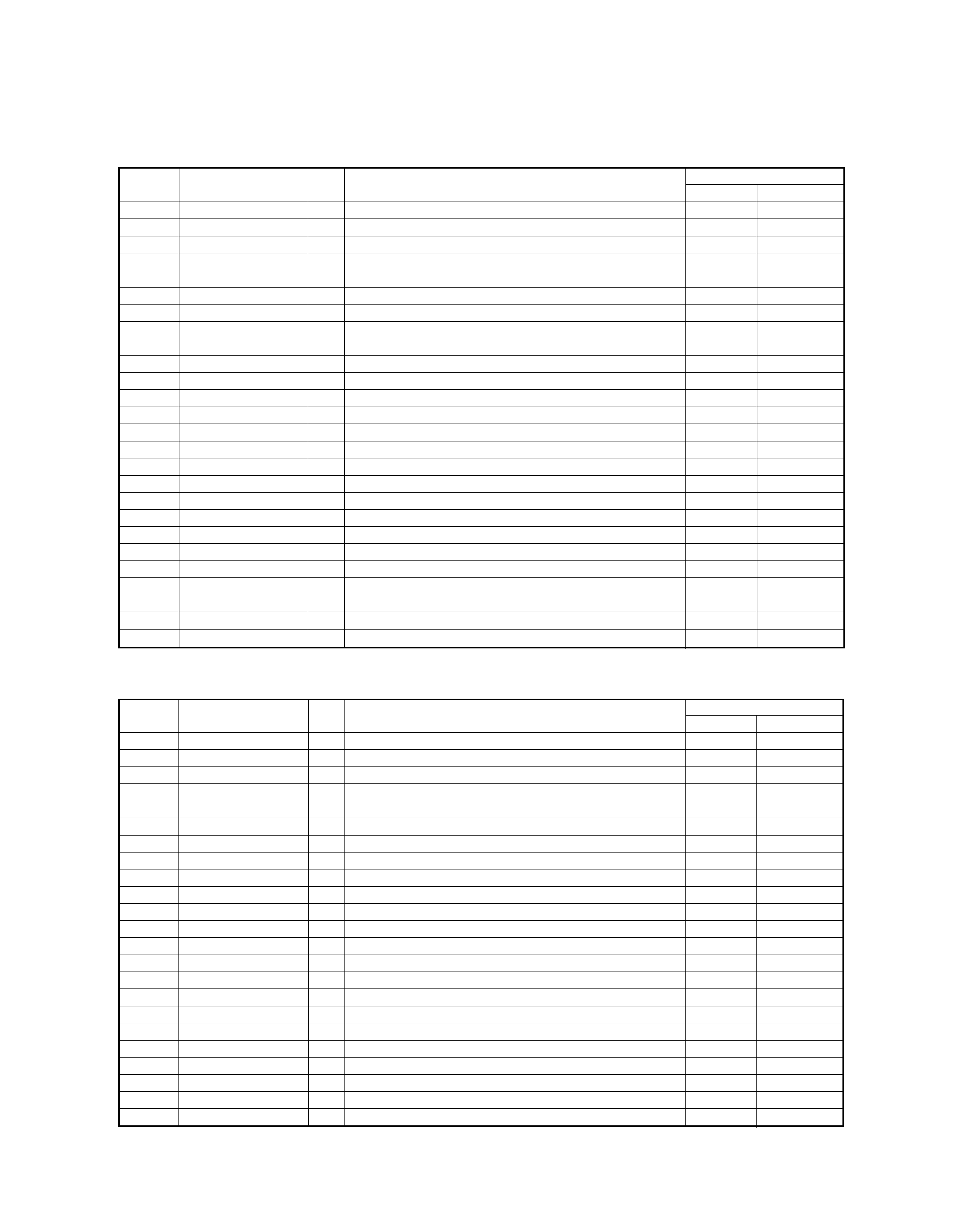
CIRCUIT DESCRIPTION
Port No.
Port Name
I/O
Function
ACTIVE
HL
1
P60
O
DSP (IC3) reset output.
2
P61
-
Unused.
3
P62
O
DSP (IC3) power down control.
ON
OFF
4
P63
-
Unused.
5~12
P50~P57
-
Unused.
13~16
P20~P23
-
Unused.
17
VDD
-
+3.0v power supply.
18
PB0
-
Unused.
19
VSS
-
GND
20
XI,PB1
-
Unused.
21
XO
-
Unused.
22
VDD
-
+3.0v power supply.
23
OSCI
I
Crystal oscillation circuit input.
24
OSCO
O
Crystal oscillation circuit output.
25
MODE
-
Connected to VDD.
26
MCLK
O
DSP (IC15) command clock signal output.
27
MDATA
O
DSP (IC15) data signal output.
28
MLD
O
DSP (IC15) command load signal output.
29
DSPRST
O
DSP (IC15) reset signal output.
30
IPFLAG
I
Unused.
31,32
PCON4,3
-
Unused.
33
PCON2
O
RF AMP power down control.
34
AVDD
-
+3.0v analog power supply.
35
PCON1
O
System power supply control.
ON
36
AMUTE
O
Audio mute control.
ON
37
HPMUTE
O
Headphones mute control.
ON
38
RWSEL
O
RF gain control.
39
STAT
I
Status signal input from DSP (IC15).
40
ACDET
I
Detection port of AC adaptor.
DETECTED
41
BBST
O
Control port of bass boost.
OFF
ON
42
HOLD
I
Input port of hold switch.
OFF
ON
43
VREF-
-
GND
44
LBATT
I
Battery level detection port.
45
VOLUME
I
Input port of volume.
46
P46
O
Crystal oscillation circuit is stopped when in stop mode(Hi).
47
P47,WDOUT
-
Unused.
48
LEDDRV
-
Unused.
49
ELDDRV
-
Unused.
50
CHG
O
Rechargeable active output. Batt. charge ON : H
51
LCDSD
O
Serial data output for LCD.
52
LCDRMC
-
Unused.
53
PB5
-
Unused.
54
VREF+
-
+3.0v power supply.
55,56
PB6,7
-
Unused.
57
MP3 MLD
O
Command load output for MP3.
58
MP3 RESET
O
Reset output for MP3.
59
DATA STOP
O
Data signal output for MP3.
60
P93
-
Unused.
61
AVSS
-
GND
62,63
KEY1, 2
I
Key signal input.
64
KEYEXT
I
Remote control signal input.
65
RCHDET
I
Detection port for low rechargeable battery.
Detected : more than 0.2V
66
VDD
-
+3.0v power supply.
1. Port Description of Microprocessor
DPC-MP727/MP922
4
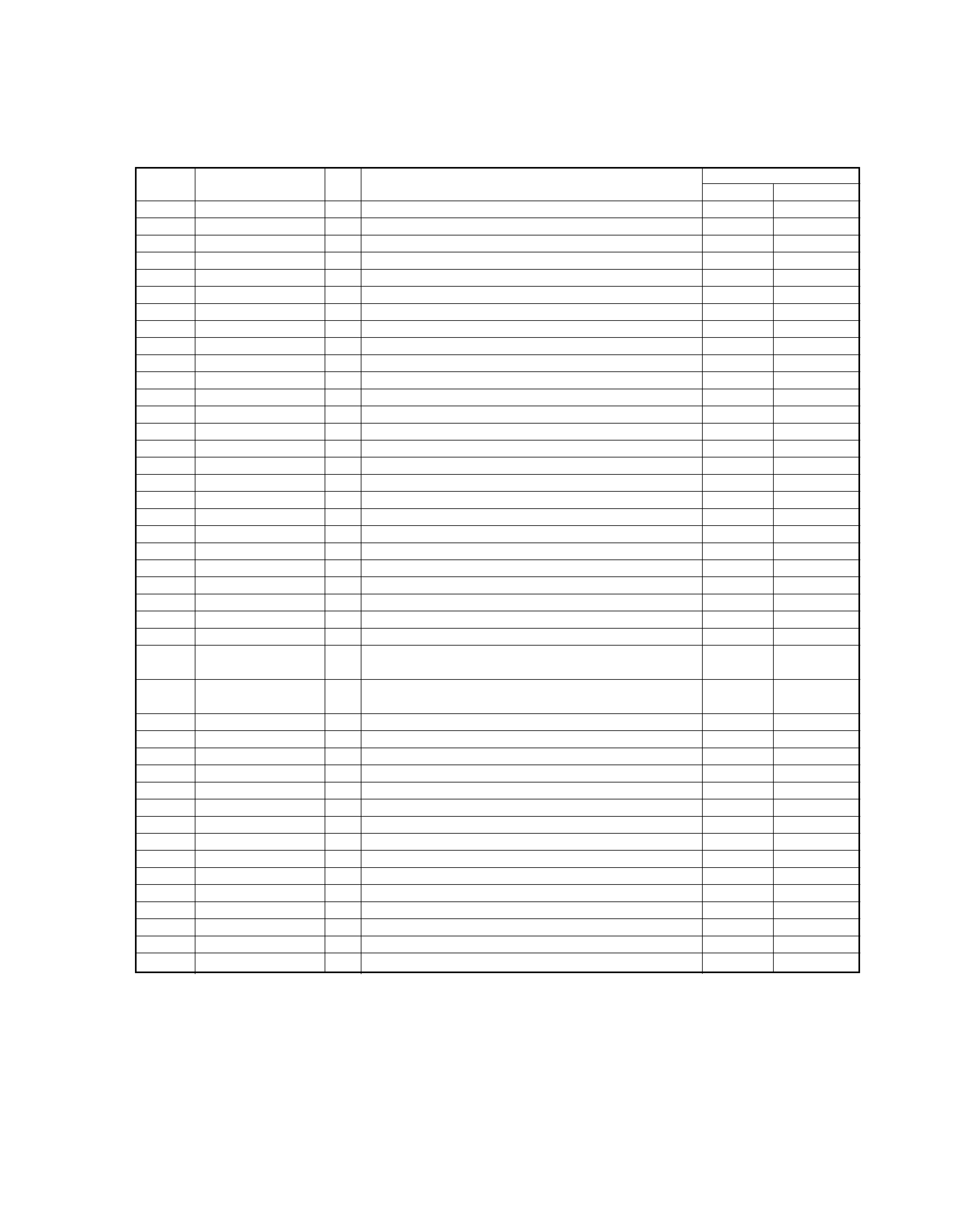
CIRCUIT DESCRIPTION
Port No.
Port Name
I/O
Function
ACTIVE
HL
67~69
P70~P72
-
Unused.
70
3T
I
RF 3Tcompensation.
71
OFTR
I
Changeover the off track.
72
P75
-
Unused.
73
PUP1
I
Pull up port.
74
PUP2
I
Pull up port.
75
NMI
I
Pull up port.
76
BLKCK
I
Sub code block clock signal input.
f BLKCK=75Hz(usual playback)
77
DOOR
I
Detection port of door switch.
78
LIMIT
I
Detection port of limit switch.
79
WUP
I
Return signal input from CPU (46pin).
80
HINT
I
Signal input from DSP (IC3) to return the usual action.
81
PA5
-
GND
82
RST
I
Reset signal input.
83
VDD
-
+3.0v power supply.
84~91
HD0~HD7
I/O
Data bus (0~7) input/output.
92
VSS
-
GND
93
HCNTL0
O
Control command output for reading and writing.
94
HCNTL1
O
Control command output for reading and writing.
95
HR/W
O
Read write signal output.
96
HBIL
O
Interface setting port.
97
HCS
O
CS signal output.
98
HAS
O
Interface setting port.
99
HDS
O
Interface setting port.
100
HRDY
O
Ready signal output.
Port No.
Port Name
I/O
Function
ACTIVE
HL
1
DVDD3V
-
DRAM interface power supply.
2,3
D0,D1
I/O
DRAM data input/output signal (D0,D1).
4
NEW
O
DRAM writing enable signal.
5
NRAS
O
DRAM RAS control signal.
6,7
D2,D3
I/O
DRAM data input/output signal (D2,D3).
8,9
NCAS(0,1)
O
DRAM CAS control signal (0,1).
10~19
A8~A3
O
DRAM address signal (A8~A3).
20
DVSS2
-
Digital ground.
21
DVDD2
-
Digital power supply.
22
SPOUT
O
Spindle motor drive signal output.
23
TRVM
O
Traverse drive positive output.
24
TRVP
O
Traverse drive negative output.
25
TRM
O
Tracking drive positive output.
26
TRP
O
Tracking drive negative output.
27
FOM
O
Focus drive positive output.
28
FOP
O
Focus drive negative output.
29
FBAL
O
The balance adjustment for the focus error.
30
TBAL
O
The balance adjustment for the tracking error.
31
VREF
I
DA reference voltage input.
32
FE
I
Focus error signal input.
33
TE
I
Tracking error signal input.
34
FRENV
I
RF envelope signal input.
35
OFT
I
Off track signal input.
Off Track
2. Port Description of DSP IC (IC15)
DPC-MP727/MP922
5
CIRCUIT DESCRIPTION
Port No.
Port Name
I/O
Function
ACTIVE
HL
36
NRFDET
I
RF detection signal input.
Detected
37
BDO
I
Drop out signal input.
Drop Out
38
LDON
-
Unused.
39
ARF
I
RF signal input.
40
IREF
I
Reference current input.
41
ADPVCC
I
AD reference voltage input.
42
DSLF
O
DSL loop filter output.
43
DSLF2
O
DSL unbalance current correction.
44
PLLF
O
PLL loop filter output.
45
VCOF
O
Jitter free VCO loop filter terminal.
46
AVDD2
-
Analog power supply.
47
AVSS2
-
Analog ground.
48
OUTL
O
L ch line output.
49
AVSS1
-
GND
50
OUTR
O
R ch line output.
51
AVDD1
-
Analog power supply.
52
FSEL
I
Noise filter ON/OFF switching input.
Off
On
53
TMOD1
-
Connected to analog ground.
54
TMOD2
-
Connected to analog ground.
55
FLAG
-
Unused.
56
IPFLAG
O
Flag signal output.
57~59
EXT(0~2)
I/O
Command change over : Expander input/output port (0~2).
60
TX
-
Unused.
61
MCLK
I
Microprocessor command clock signal input.
62
MDATA
I
Microprocessor command data signal input.
63
MLD
I
Microprocessor command load signal input.
Load
64
BLKCK
O
Sub code block clock signal output.
fBLKCK=75Hz(normal playback)
65
SQCK
I/O
Command change over : Sub code Q register external
clock input.
66
SUBQ
O
Command change over : Sub code Q data output.
67
DMUTE
I/O
Command change over : Muting input.
Mute
68
STAT
O
Status signal output.
69
NRST
I
Reset signal input.
Reset
70
SPPOL
O
Spindle motor drive signal output (polar output).
71
PMCK
O
88.2kHz clock signal output.
72
SMCK
-
Unused.
73
SUBC
-
Unused.
74
SBCK
-
Connected to digital power supply.
75
NCLDCK
-
Unused.
76
NTEST
-
Connected to digital power supply.
77
X1
I
Crystal oscillation circuit input.
f=16.9344MHz
78
X2
O
Crystal oscillation circuit output. f=16.9344MHz
79
DVDD1
-
Digital power supply.
80
DVSS1
-
Digital ground.