General
Power source
DC
........................
.............
........................
.......................
.....
...........
3.6 V (rechargeable lithium-ion
battery NB-L10A x 1)
DC 5 V (AC adaptor)
AC 230 V, 50 Hz
DC 3 V
Separately available battery case
(commercially available, "AA"
size, alkaline battery x 2)
DC 4.0 V : Separately available car
adaptor, DC-C70
(for cars with a 12-24 V DC
negative earth electrical system)
Power consumption
7 W (AC adaptor)
Output power
RMS; 20 mW (10 mW + 10 mW)
(0.2 % T.H.D.)
Charging time
Approx. 3.0 hours
(When using the AC adaptor included
with the unit)
Battery life
Note:
The battery case is only sold in certain areas. For more details,
please ask your dealer.
The continuous recording time is for analogue input when the
volume level is set to "VOL 0".
The continuous play time shows the value when the volume level is
set to "VOL 15".
The above values are the standard values when the unit is charged
and used at an ambient temperature of 20
oC.
The operating time when using alkaline batteries may be different,
depending on the type and manufacturer of the batteries, and on
the operating temperature.
Input sensitivity
Output level
Dimensions
Width: 87.0 mm (3-7/16")
Height: 29.4 mm (1-3/16")
Depth: 81.5 mm (3-7/32")
Weight
219 g (0.49 lbs.) with rechargeable
battery
Input socket
Line/optical digital, microphone
(powered by the main unit)
Output socket
Headphones (impedance: 32
ohms)/remote control unit
MiniDisc Recorder
Type
Portable MiniDisc recorder
Signal readout
Non-contact, 3-beam semi-coductor
laser pick-up
Audio channels
Stereo 2 channels/monaural (long-
play mode) 1 channel
Frequency response
20 - 20,000 Hz (
± 3 dB)
Rotation speed
Approx 400 - 900 rpm
Error correction
ACIRC (Advanced Cross Interleave
Reed-Solomon Code)
Coding
ATRAC (Adaptive Transform
Acoustic Coding), 24-bit computed type
Recording method
Magnetic modulation overwrite method
Sampling frequency
44.1 kHz (32 kHz and 48 kHz
signals are converted to 44.1 kHz,
and then recorded.)
Wow and flutter
Unmeasurable (less than
±0.001% W.peek)
Continuous recording:
Approx. 4.5 hours
Continuous recording:
Approx. 4 hours
Continuous recording:
Approx. 8.5 hours
Continuous play:
Approx. 6.5 hours
Continuous play:
Approx. 8 hours
Continuous play:
Approx. 14.5 hours
Headphones
--
10 mW +
32 ohms
10 mW
LINE
300mV (-12dB)
--
50 k ohms
Maximum
output level
Specified output
Recording level
Reference input level
Input impedance
MI C H
0.25 mV
10 k ohms
MIC L
2.5 mV
10 k ohms
LINE
100 mV
20 k ohms
Load
impedance
When using two,
commercially available,
high capacity, "AA" size,
alkaline batteries (in the
separately available battery
case)
When using the recharge-
able battery NB-L10A (fully
charged) included with the
unit
When using two, commercially
available, high capacity, "AA"
size batteries with the
rechargeable battery (fully
charged)
....................
............
............
...............
....................
....................
.......................
..........................
...........................
.....................
......................
.......................................
...................................
...................................
DIGITAL
EDIT
& RECORDING
RECORDING
REC
LEVEL
/CURSOR
CHARACTER
AUTO
MARK
SYNC/F.PLAY
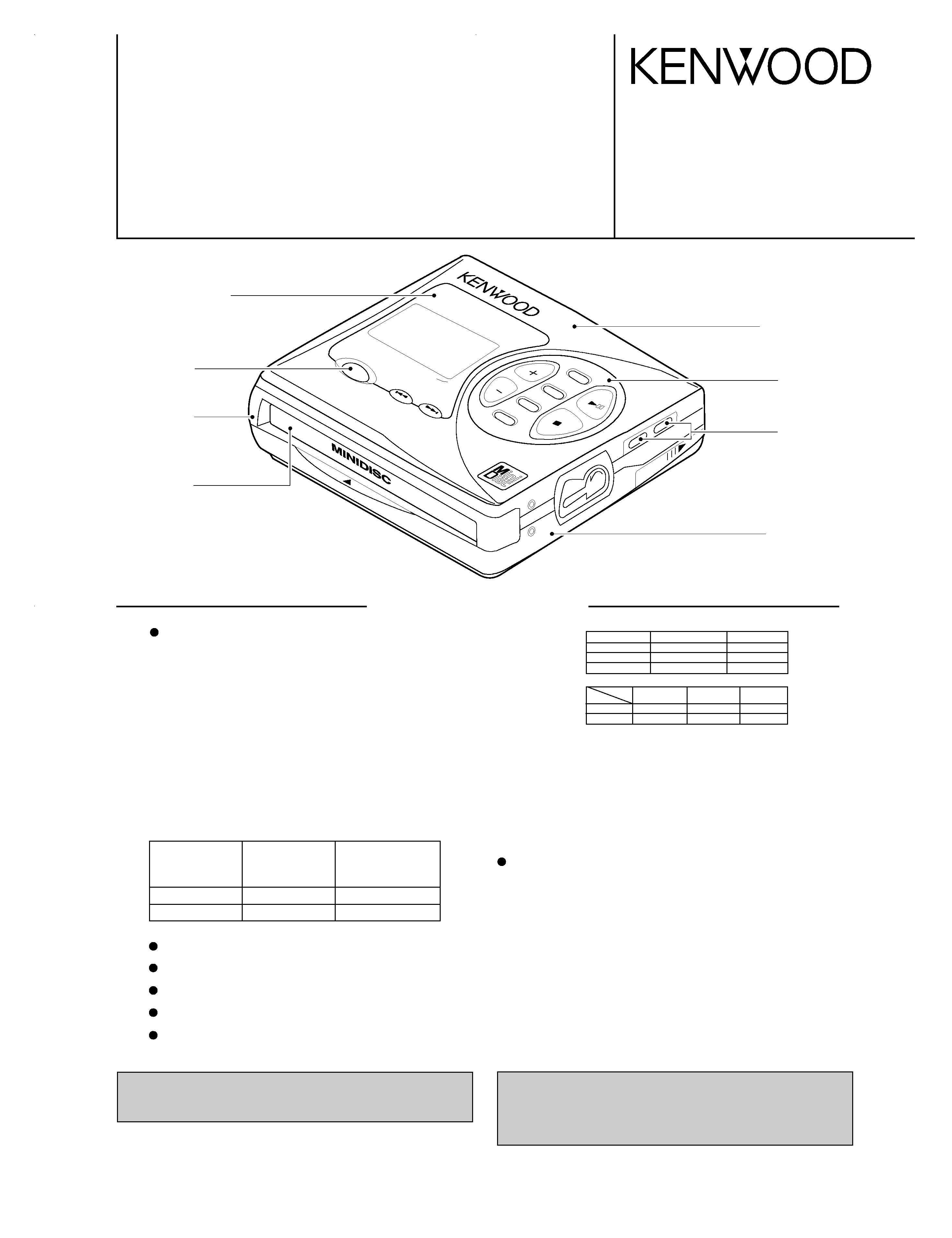
VOLUME/NAME
PORTABLE
MD
RECORDER
DMC-J7R
BASS/DELETE
MODE/INSERT
OPEN
DISP
EDIT
OFF
ENTER
EJE
CT
PORTABLE MD RECORDER
DMC-J7R
SERVICE MANUAL
© 1998-6/B51-5441-00 (K/K) 3163
Transparency cover *
(B10-)
Knob
(K29-2270-08)
Bottom cabinet *
(A02-)
Front cabinet
(A02-2808-08)
MD cover
(F07-1638-08)
Knob
(K27-2272-08)
Upper case assy
(A02-2814-08) : S
(A02-2862-08) : B
Knob base
(A02-2816-08)
* Refer to parts list on page 26.
S: Silver, B: Blue
In compliance with Federal Regulations, following are reproduc-
tions of labels on, or inside the product relating to laser product
safety.
KENWOOD-Crop. certifies this equipment conforms to DHHS
Regulations No. 21 DFR 1040. 10, Chapter 1, Subchapter J.
DANGER : Laser radiation when open and interlock defeated.
AVOID DIRECT EXPOSURE TO BEAM
SPECIFICATIONS
DMC-J7R(K) COVER1,1P( 98.11.30 1:44 PM y[W 2
DMC-J7R
2
CONTENTS / ACCESSORIES / CAUTIONS
SPECIFICATIONS .........................................Top cover
CONTENTS / ACCESSORIES / CAUTIONS ...............2
CONTROLS .................................................................3
DISASSEMBLY FOR REPAIR .....................................4
BLOCK DIAGRAM .......................................................6
CIRCUIT DESCRIPTION .............................................7
TROUBLE SHOOTING ................................................8
NOTE ON SCHEMATIC DIAGRAM ...........................14
PARTS DESCRIPTIONS ...........................................15
WAVEFORMS OF MD CIRCUIT ...............................16
PC BOARD ................................................................17
SCHEMATIC DIAGRAM ............................................21
EXPLODED VIEW .....................................................24
PARTS LIST...............................................................26
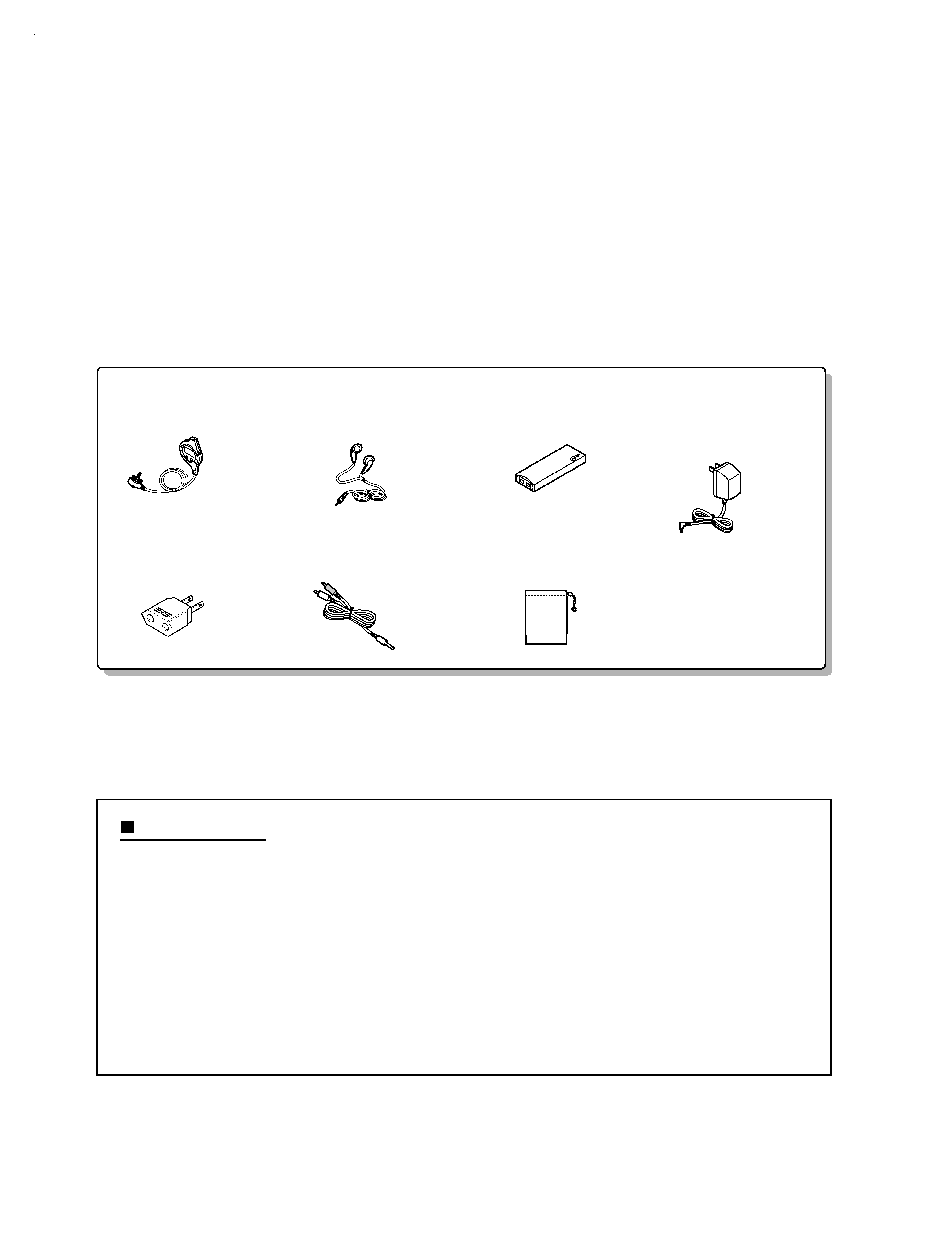
Contents
Accessories
Remote control (1)
(A70-1210-08)
Stereo headphone (1)
(W01-0941-05) : K,P type
(W01-0948-05) : T,E,E1,M type
Rechargeable battery (1)
(W03-5946-08): NB-L10A
AC adapter (1)
(W08-0669-08) : M type
(W08-0672-08) : E,E1 type
(W08-0673-08) : T type
(W08-0674-08) : K,P type
AC plug adapter (1)
(E03-0115-05) : M type
Connecting cord (1)
(E30-2836-08)
Carrying case (1)
(W01-0955-08)
How to reset
When this product is subjected to strong
external interference (mechanical shock,
excessive static electricity, abnormal sup-
ply voltage due to lightning, etc.) or if it is
operated incorrectly, it may malfunction. If
such a problem occurs, do the following:
1. Unplug the AC adaptor from the AC
socket.
2. Remove the battery.
3. Leave the unit completely unpowered
for approximately 30 seconds.
4. Plug the AC adaptor back into the AC
socket and retry the operation.
If strange sounds, smell or smoke come
out of the unit or an object is dropped into
the unit, remove the AC adaptor from the
AC socket immediately and contact an au-
thorized KENWOOD service centre.
Cautions
DMC-J7R(K) COVER1,1P( 98.11.30 1:44 PM y[W 3
Error messages
Meaning
Remedy
BATT EMPTY
The battery run down.
Charge the rechargeable battery or
replace the alkaline batteries (or use
the AC adaptor for power).
BLANK DISC
Nothing is recorded.
Replace the disc with a recorded
disc.
Can't COPY
No copy can be made because of
the SCMS copyright system.
Record using the analogue cable.
Can't EDIT
A track cannot be edited.
Change the stop position of the
track and then try editing it.
Can't REC
Recording cannot be performed
correctly due to vibration or shock
in the unit.
Re-record or replace it with another
recordable disc.
Can't WRITE
Editing is impossible.
Check the number of tracks.
DEFECT
The disc is scratched.
If the sound you hear is not right,
try recording again.
Replace the disc with another
recordable disc.
Din UNLOCK
Poor connection of the digital cable.
Connect the digital cable securely.
DISC ERROR
The disc is damaged.
Reload the disc or replace it.
DISC FULL
The disc is out of recording space.
Replace it with another recordable
disc.
HOLD
The unit is in the safety mode.
Return the HOLD switch to its
original position.
LOCKED
LOCK ERROR
The EJECT lever was moved
during recording or editing.
Turn off the power and remove the
MiniDisc.
NO DISC
A disc has not been loaded.
Load a disc.
PB DISC
PROTECTED
The disc is write protected.
You tried to record on a playback-
only disc.
Move the write protection knob
back to its original position.
Replace it with a recordable disc.
POWER ?
Improper power is being supplied.
Use one of the specified power
sources.
SORRY
Since a track number is currently
being located or written to, the unit
cannot accept your command.
Wait for a while and try the
operation again.
SYSTEM ERR
You have come to the conclusion
that the unit is out of order.
To have it repaired, go to the
distributor where you purchased the
unit.
TEMP OVER
The temperature is too high.
Turn off the power, and wait for a
while.
TOC ERROR
A large portion of the disc has been
damaged.
Replace it with another recorded
disc.
TOC FULL
There is no space left for recording
character information (track names,
disc names, etc.).
Replace it with another recordable
disc.
Tr. Protect
The track has been protected from
being erased.
Edit the track with the device on
which it was recorded.
U TOC ERROR
A large portion of the disc has been
damaged.
There is an error in the recorded
signal.
Replace it with another recorded
disc.
Erase all of the signal errors, and
then try recording again.
? DISC
A disc which contains data other
than music was played.
There is an error in the signal from
the disc.
A disc which contains non-music
data cannot be played.
Replace it with another recorded
disc.
ERROR MESSAGES
DMC-J7R
3
CONTROLS
Main Unit
1. Monaural Long-Play Mode Indicator
2. Record Indicator
3. Level Meter
4. Repeat Indicator:
5. TOC Indicator
6. Battery Indicator:
7. Random Indicator
8. Track Number Indicator
9. Character/Time Information Indicator
10. Synchro Recording Indicator
11. Disc Mode Indicator
12. Disc Name Indicator
13. Track Name Indicator
14. Remaining Recording Time Indicator
15. Total Track Number Display
16. Record/Track Mark Button
17. Volume/Name Select Buttons: +, -
18. Display/Lowercase Characters Button
19. Character Button
20. Stop/Power Off/Charge Button:
/OFF
21. Play/Pause Button:
22. Fast Reverse/Fast Forward/Record-
ing LevelControl/Cursor Buttons:
/
23. Enter/Fast Play/Synchro Button
24. Edit/Auto Mark/Time Mark Button
25. Eject Lever
26. Bass/Delete Button
27. Mode/Insert Button
28. Microphone Input Socket
29. Hold Switch
30. Rechargeable Lithium-Ion Battery
Compartment
31. Optical/Line Input Socket
32. Headphones Socket
33. 5V DC Input Socket
34. Battert Case Connection Terminals
12
3 4
5
6
7
8
9
10
11
12
13
14 15
16
17 18 19 20 21
22
23 24 25 26 27
29
34
30
33
28
31
32
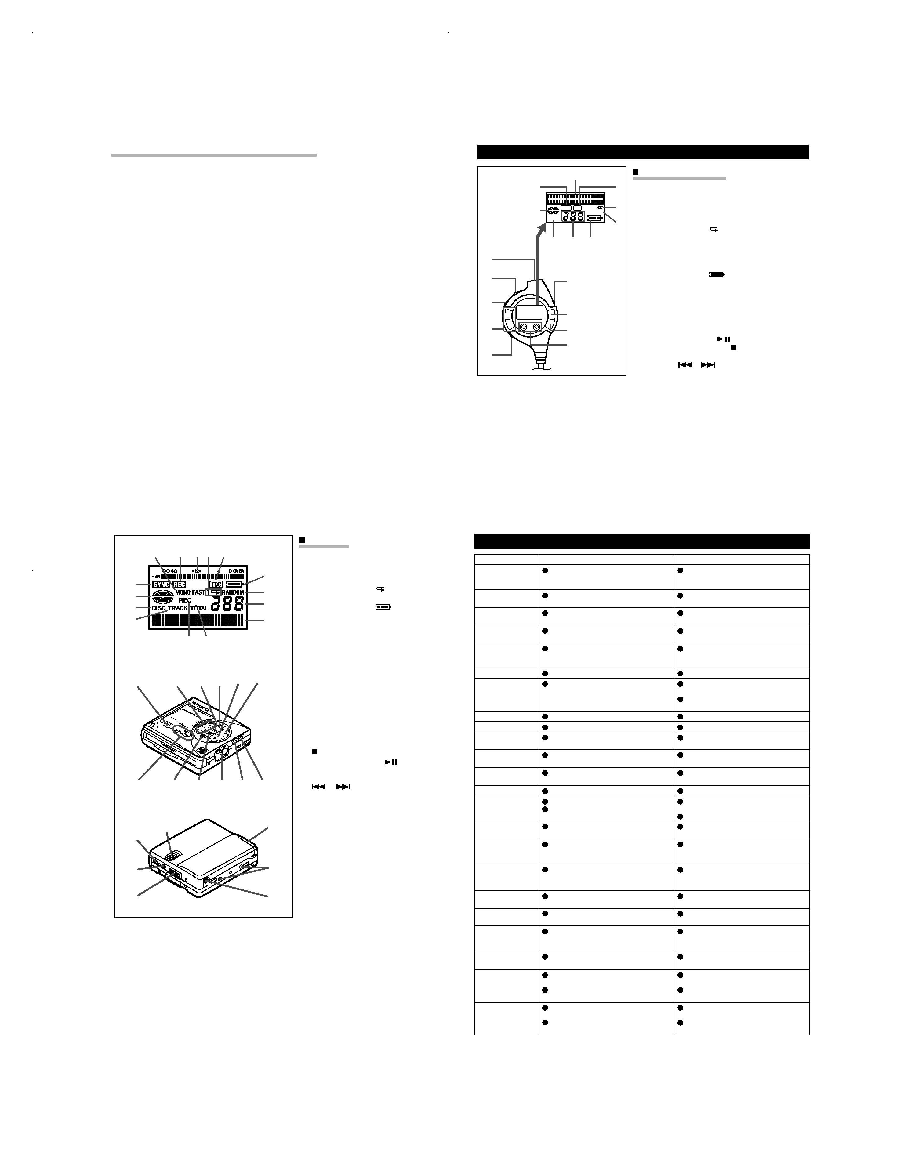
Remote Control Unit
1. Synchro Recording Indicator
2. Character/Time Information
Indicator
3. Record Indicator
4. Repeat Indicator:
5. Random Indicator
6. Disc Mode Indicator
7. Total Track Number Display
8. Track Number Indicator
9. Battery Indicator:
10. Headpones Socket
11. Hold Switch
12. Play Mode Button
13. Volume Buttons: +, -
14. Bass Button
15. Display Button
16. Play/Pause Button:
17. Stop/Power Off Button:
18. Fast Reverse/Fast Forward
Buttons:
/
RANDOM
TOTAL
1
REC
SYNC
12
13
14
11
15
16
17
18
10
1
6
2
3
4
5
78
9
NAMES OF CONTROLS AND INDICATORS
÷ A rechargeable lithium-ion battery is
the only kind that can be used.
Even if the battery supplied with the
unit is not used, you should charge it
at least once every three months
because of the special quality of this
battery.
÷ The rechargeable battery can be
charged approximately 300 times.
÷ Do not use any battery other than
that specified. Use of other batter-
ies maycause malfunctions.
÷ When the operating time is reduced
to about half the normal amount of
time, even after a full charge is per-
formed, replace the battery with a
new one.
÷ When charging or when using the
rechargeable battery, use it within
an ambient temperature range of
5°C to 35°C.
÷ If the rechargeable battery is used in
a cold environment, the operating
time will decrease.
Since the rechargeable battery is
vulnerable to damage, please note
the following.
÷ Do not carry the battery in your
pocket or a bag together with metal
objects (keys, coins, jewelry, etc.).
The battery may short out and gen-
erate significant amounts of heat.
÷ Do not short-circuit the terminals as
they will become very hot and will
damage the battery.
÷ Do not dip the battery in water, do
not dispose of it in a fire, and do not
take it apart.
To avoid damaging the battery and
shortening its service life, please
note the following.
÷ Do not drop or subject the battery to
shock.
÷ Do not insert objects (metal etc.)
into the battery compartment of this
product or into the rechargeable bat-
tery. Do not get the terminals dirty.
If the rechargeable terminals are
dirty, the operating time may be
shortened or it may not be possible
to charge the battery.
÷ After the rechargeable battery is
charged or used, it will get slightly
warm. This is normal.
7 Notes about the rechargeable battery
DMC-J7R(K) COVER1,1P( 98.11.30 1:44 PM y[W 6
DMC-J7R
4
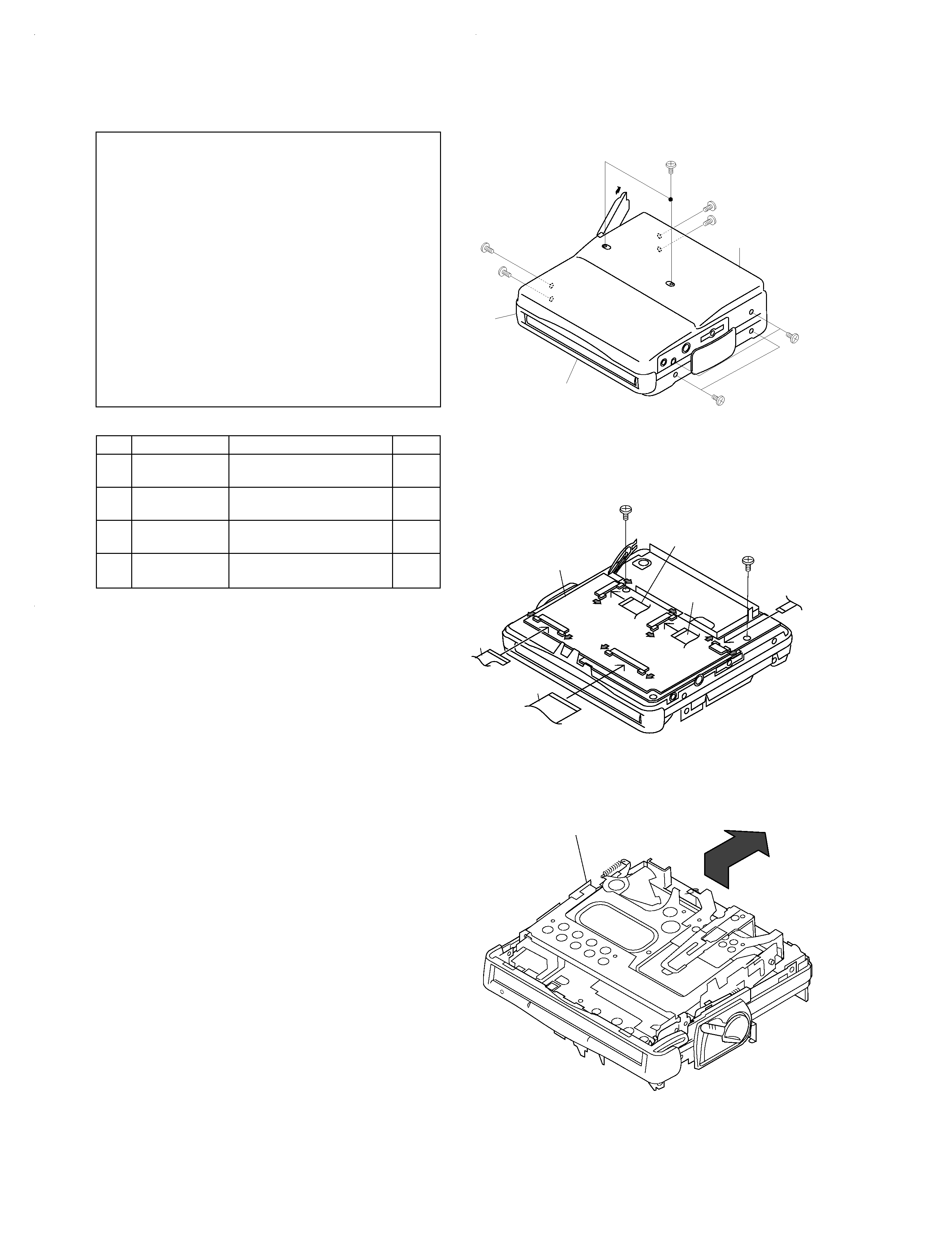
DISASSEMBLY FOR REPAIR
1
Bottom Cabinet
1. Open the battery Lid.
8-1
2. Screw ..................... (A1) x6
2
Top Cabinet
1. Screw ..................... (B1) x4
8-1
2. Flat Cable ............... (B2) x2
3
Main PWB
1. Screw .................... (C1) x2
8-2
2. Flat Cable ............... (C2) x3
4
Mechanism Unit
1. Lift the left side, and remove
8-3
in the arrow direction.
Caution on Disassembly
Follow the below-mentioned notes when disassembling
the unit and reassembling it, to keep it safe and ensure
excellent performance:
1. Take the battery and minidisc out of the unit.
2. When disassembling the machine, be sure to withdraw
the power plug from the socket in advance.
3. When disassemble the parts, remove the nylon band or
wire holder as necessary.
To assemble after repair, be sure to arrange the wires as
they were.
If a screw of different length is fitted to the MD mecha-
nism (the screw of the
part to be fitted to the MD
mechanism chassis), it may contact the optical pickup,
resulting in malfunction.
4. When repairing, pay due attention to electrostatic charges
of IC.
REMOVAL
PROCEDURE
STEP
FIGURE
Bottom Cabinet
Top Cabinet
Center
Cabinet
Pull
(A1)x1
Ø1.4x2mm
(A1)x1
Ø1.4x2mm
(A1)x2
Ø1.4x2mm
(A1)x2
Ø1.4x2mm
(B1)x1
Ø1.4x2mm
(B1)x1
Ø1.4x2mm
(B1)x2
Ø1.4x2mm
Figu re 8-1
Figure 8-2
Mechanism Unit
Figure 8-3
Caution:
1. Handle carefully the main PWB and flexible PWB.
After removing the flexible PWB (*1) for optical pickup from
the connector, wrap the front end of flexible PWB in conduc-
tive aluminum foil so as to protect the optical pickup from
electrostatic damage.
2. When removing the mechanism from the cabinet or when
installing it, it is advisable to
rotate the unit lock plate to lower the holder section.
(C1)x1
Ø1.7x2.5mm
(C1)x1
Ø1.7x2.5mm
Pull
Pull
Pull
Pull
Pull
Pull
Pull
Pull
(B2)x1
(B2)x1
(C2)x1
(C2)x1
(C2)x1
Main PWB
DMC-J7R(K) COVER1,1P( 98.11.30 1:44 PM y[W 7
DMC-J7R
5
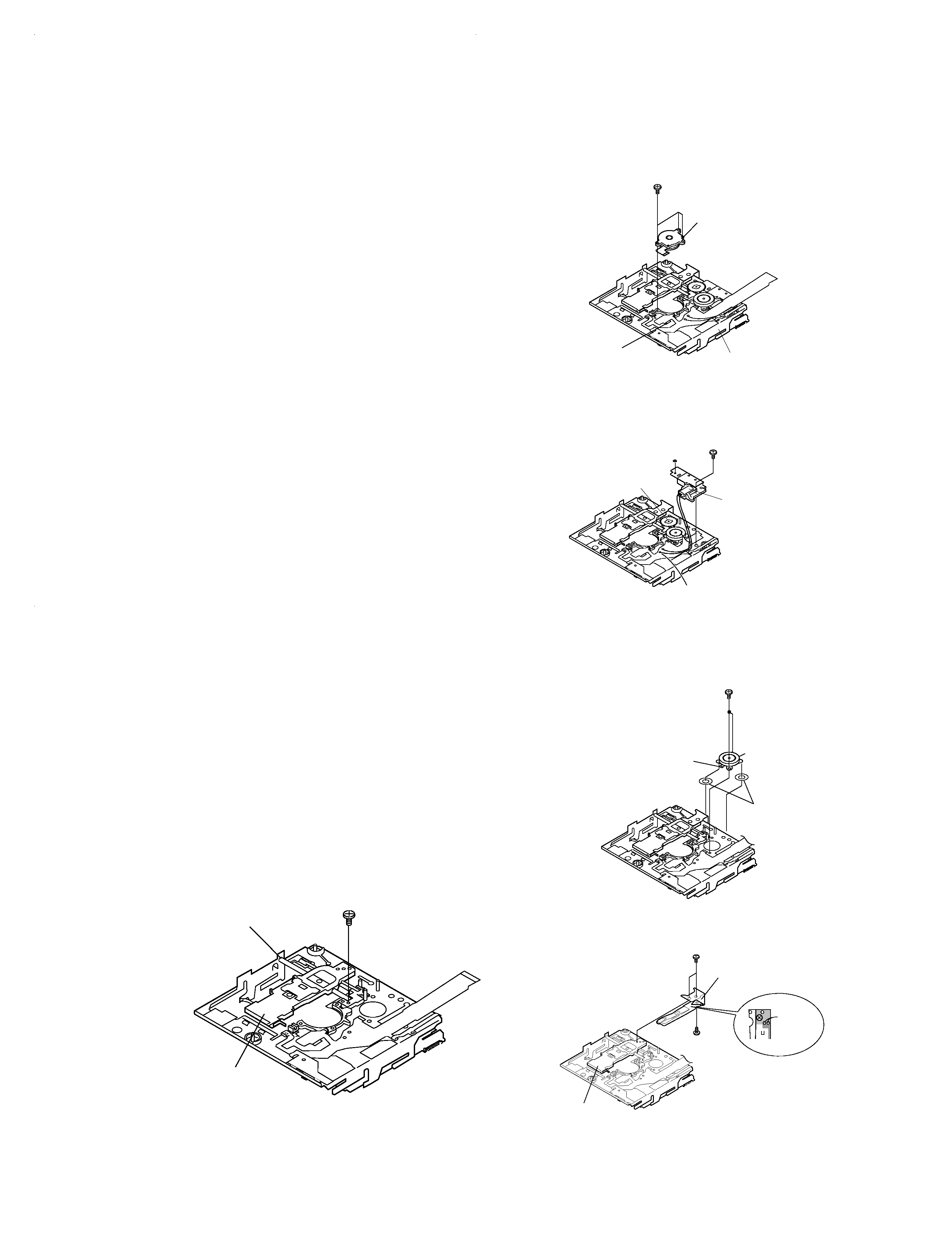
DISASSEMBLY FOR REPAIR
Remove the mechanism according to the disassembling meth-
ods 1 to 3. (See Page 8.)
How to remove the spindle motor (See Fig. 9-1.)
1. Remove the solder joint (A1) x 1 of flex PWB.
2. Remove the stop (A2) x 3 pcs. and remove the spindle
motor.
Figure 9-5
Flexible PWB
solder joint
(A1) x1
Spindle Motor
(A2)x3
ø1.4x2.8mm
MDMechanism
Figure 9-1
(B1)x2
Remove the solder joint
Stop Washer
(B2)x1
Drive Gear
(B3)x1
Lift Motor
(B4)x1
ø1.4x2.2mm
Figure 9-2
Figure 9-3
(E1)x1
ø1.7x2.5mm
Shaft
Pickup Unit
How to reinstall the optical pickup unit
(See Fig. 9-5.)
1. Remove the screws (E1) x 1 pcs.
2. Remove the soldering joint (C2) x2 places of flex PWB, and
remove the sled motor.
How to remove the magnetic head
(See Fig. 9-4.)
1. Remove the screw (D1) x 2 pc.
2. Remove the screw (D2) x1 which connects the magnetic
head to the head relay flex PWB, and remove the soldering
joint (D3) x2 pcs.
Note:
Mount carefully so as not to damage the magnetic head.
(D1)x2
Ø1.4x1.8mm
(D1)x1
Ø1.4x1.5mm
Pickup Unit
Magnetic Head
Solder
joint
(D3)x2
Figure 9-4
How to remove the lift motor (See Fig. 9-2.)
1. Remove the solder joint (B1) x 2 of slide motor lead wire.
2. Remove the stop washer (B2) x 1 pc., and remove the drive
gear (B3) x 1 PC.
3. Remove the screw (B4) x 1, and remove the lift motor.
Note:
Take care so that the motor gear is not damaged.
(If the gear is damaged, noise is raised in search mode.)
How to remove the sled motor (See Fig. 9-3.)
1. Remove the solder joint (C1) x 2 of slide motor lead wire.
2. Remove the screw (C2) x 2, and remove the sled motor.
Note:
Take care so that the motor gear is not damaged.
(If the gear is damaged, noise is raised in search mode.)
(C1)x2
ø1.4x1.2mm
Sled Motor
Washer x2
(C2)x2
Mecha Flexible PWB
solder joint
DMC-J7R(K) COVER1,1P( 98.11.30 1:44 PM y[W 10