D40-1132-05
CASSETTE MECHANISM ASSY
SERVICE MANUAL
C
1999-5 PRINTED IN KOREA
B51-7505-00 (K) 482
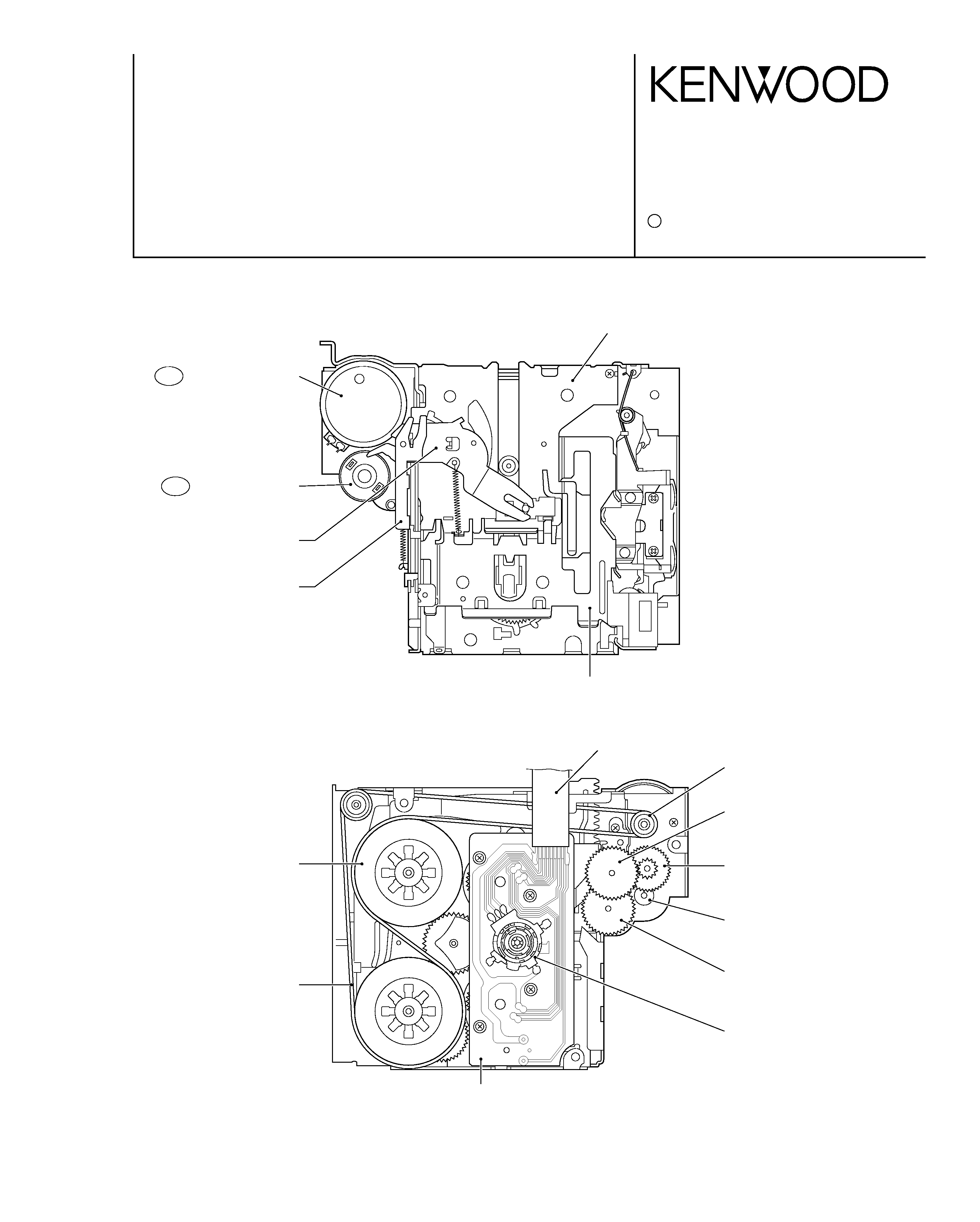
Top View
Bottom View
] CASE LIFTER
MOTOR PULLY
(MAIN MOTOR ASS'Y)
A GEAR
(SUB MOTOR ASS'Y)
FFC CABLE
7 C GEAR
5 B GEAR
6 D GEAR
MODE SW
REEL PWB
CM1 MAIN MOTOR ASS'Y
CM2 SUB MOTOR ASS'Y
| PS ACTUATOR PLATE
* EJECT LEVER
, FLY WHEEL
-- MAIN BELT
\ CASSETTE CASE
D40-1132-05
2
CONTENTS / DISASSEMBLY FOR REPAIR
CONTENTS / DISASSEMBLY FOR REPAIR.............2
MECHANISM DESCRIPTION ..................................13
ADJUSTMENT..........................................................19
EXPLODED VIEW ....................................................20
PARTS LIST .............................................................21
CONTENTS
DISASSEMBLY FOR REPAIR
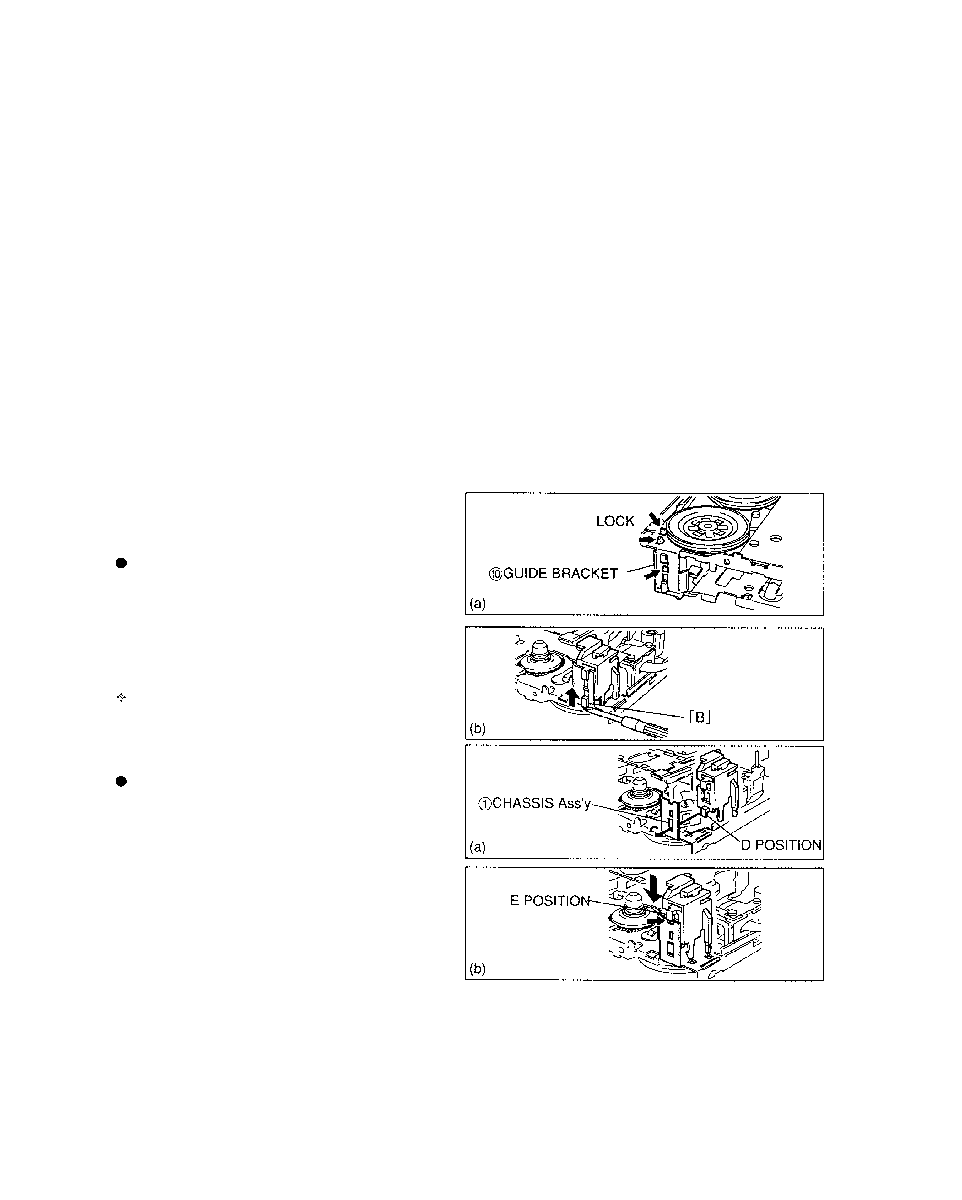
1.1. GUIDE BRACKET
CAUTION:
This part is damageable during disassembling, and it cannot
be reused.
Disassembling
(a) Note that
0GUIDE BRACKET is locked at three places
shown in figure.
(b) Set the mechanism in "R.PLAY" mode (see 2.1 Manual
Operation).
(c) Push "B" portion strongly upward with a proper tool, and
the Bracket will be unlocked at once.
If the above unlocking failed, break the lock with nippers
(In such a case, take care not to allow debris to enter the
deck.)
Reassembling
(a) From the side of PINCH ROLLER ARM Ass'y, first insert
"D" portion into a hole in
1CHASSIS Ass'y.
(b) Adjusting three locks and "E" portion, push the Bracket
down until it clicks.
(c) Make sure that the Bracket is locked at three places.
(hooks are engaged with the Chassis.)
D40-1132-05
3
DISASSEMBLY FOR REPAIR
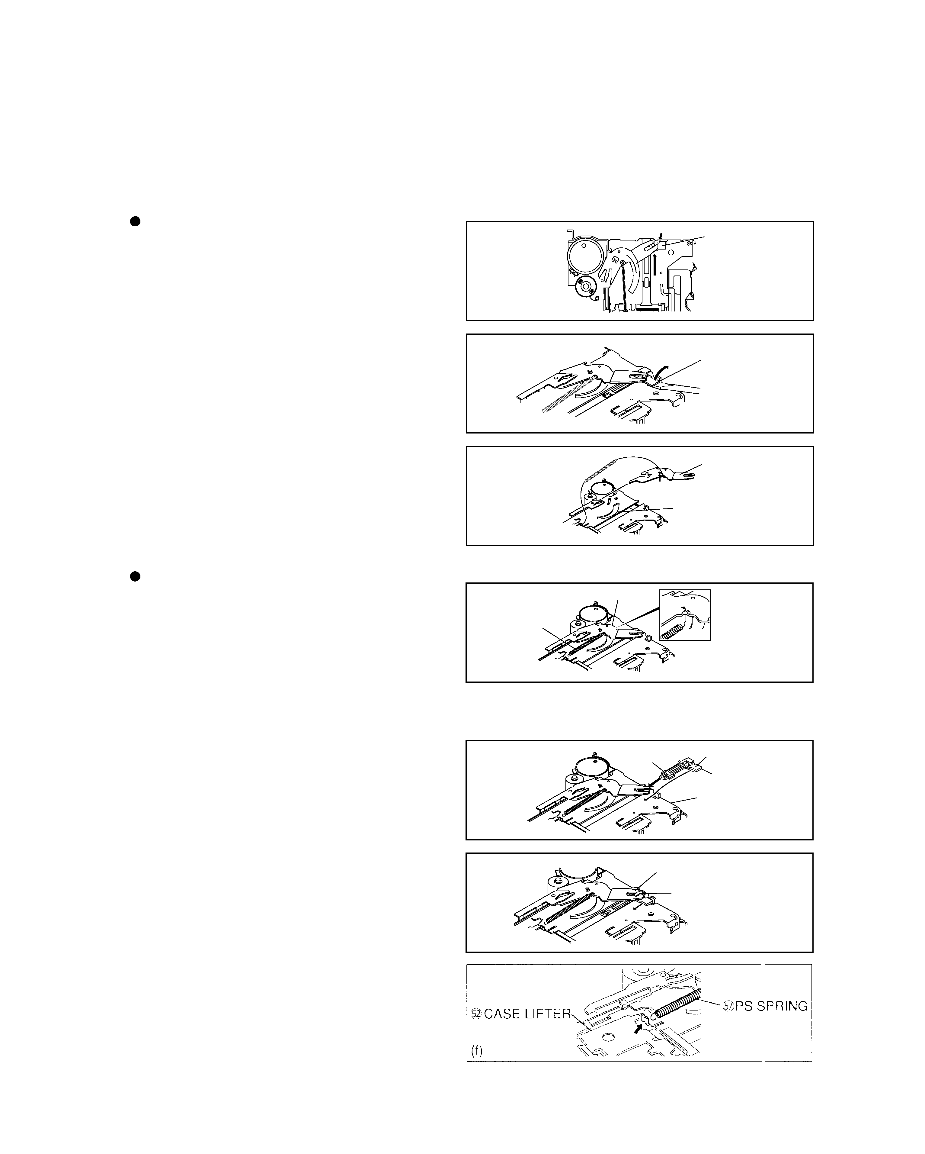
Disassembling
(a) Rotate
7D GEAR by hand until the position shown in fig-
ure where
`PACK SLIDER gets stuck to the stopper.
-Position traveling over the PULL.E a little.-
(b) Raising the part shown in figure with a thin edge screw-
driver, push the
`PACK SLIDER in arrow direction,
avoiding interference with the stopper.
(c) Disengage the boss from the PS ACTUATOR PLATE,
and the PACK SLIDER will be removed.
(d) Further turning CCW the
|PS ACTUATOR PLATE,
raise the Guide shown with an arrow while meeting with
the hole in
]CASE LIFTER, and the PS ACTUATOR
PLATE can be removed.
(e) At the same time, remove
"PS SPRING from the
]CASE LEFTER (if necessary), and from the |PS
ACTUATOR PLATE.
Reassembling
(a) Rotating
7D GEAR in the deck until the position where a
marker on OP PLATE Ass'y travels over the pulley a lit-
tle.
(b) Hook
"PS SPRING to the |PS ACTUATOR PLATE
from the bottom. Meeting the hole with the boss of
]CASE LIFTER, insert a bent portion into a sector hole
in the
]CASE LIFTER (step (b) in previous item).
(c) Under this condition, insert the
`PACK SLIDER so that
its "A" and "B" portions come out under and above the
]CASE LIFTER respectively.
(d) Insert the boss into
|PS ACTUATOR PLATE, and slide
toward the front.
(e) Rotate the D GEAR clockwise to set up the EJECT sta-
tus.
(f) Hook another end
"PS SPRING to the ]CASE LIFTER.
(a)
(b)
(d)
(b)
(c)
(d)
`PACK SLIDER
`PACK SLIDER
`PACK SLIDER
|PS ACTUATOR PLATE
|PS ACTUATOR PLATE
|PS ACTUATOR PLATE
]CASE LIFTER
]CASE LIFTER
"PS SPRING
B
A
C
1.2.
`PACK SLIDER/|PS ACTUATOR PLATE
CAUTION:
The PACK SLIDER is damageable during disassembling, and it cannot be reused. and it cannot be reused.
D40-1132-05
4
DISASSEMBLY FOR REPAIR
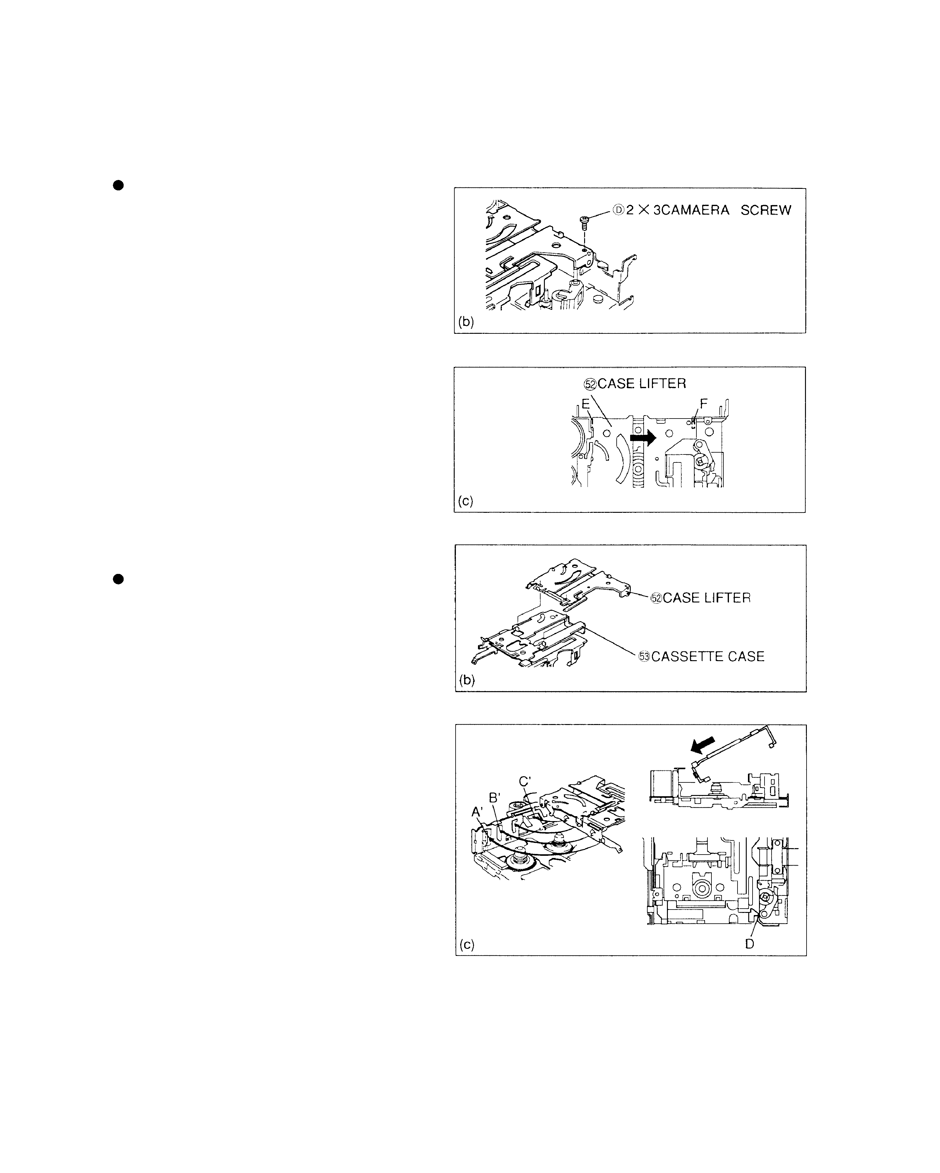
1.3.
\CASSETTE CASE/]CASE LIFTER
Disassembling
(a) Set the mechanism in EJECT POSITION.
(b) Remove
D2x3 CAMERA SCREW.
(c) Push
]CASE LIFTER in arrow direction so that "E" and
"F" portions are disengaged.
Reassembling
(a) Confirm that the mechanism is at EJECT position.
(b) Meeting the holes in
]CASE LIFTER with the holes in
\CASSETTE CASE as shown in figure, assemble these
parts.
(c) Meeting A, B, C with A', B', C' respectively, insert the
Cassette Case obliquely. (Note that "D" portion may get
stuck.)
(d) When the Cassette Case becomes horizontal, confirm that A, B, C are engaged, then adjust fitting at E and F portions in
Fig.(c) in previous item, and insert the Case completely. (Step (c) in previous item) (Fitting is over when no gap is found.)
(e) Tighten 2x3 SCREW.
D40-1132-05
5
DISASSEMBLY FOR REPAIR
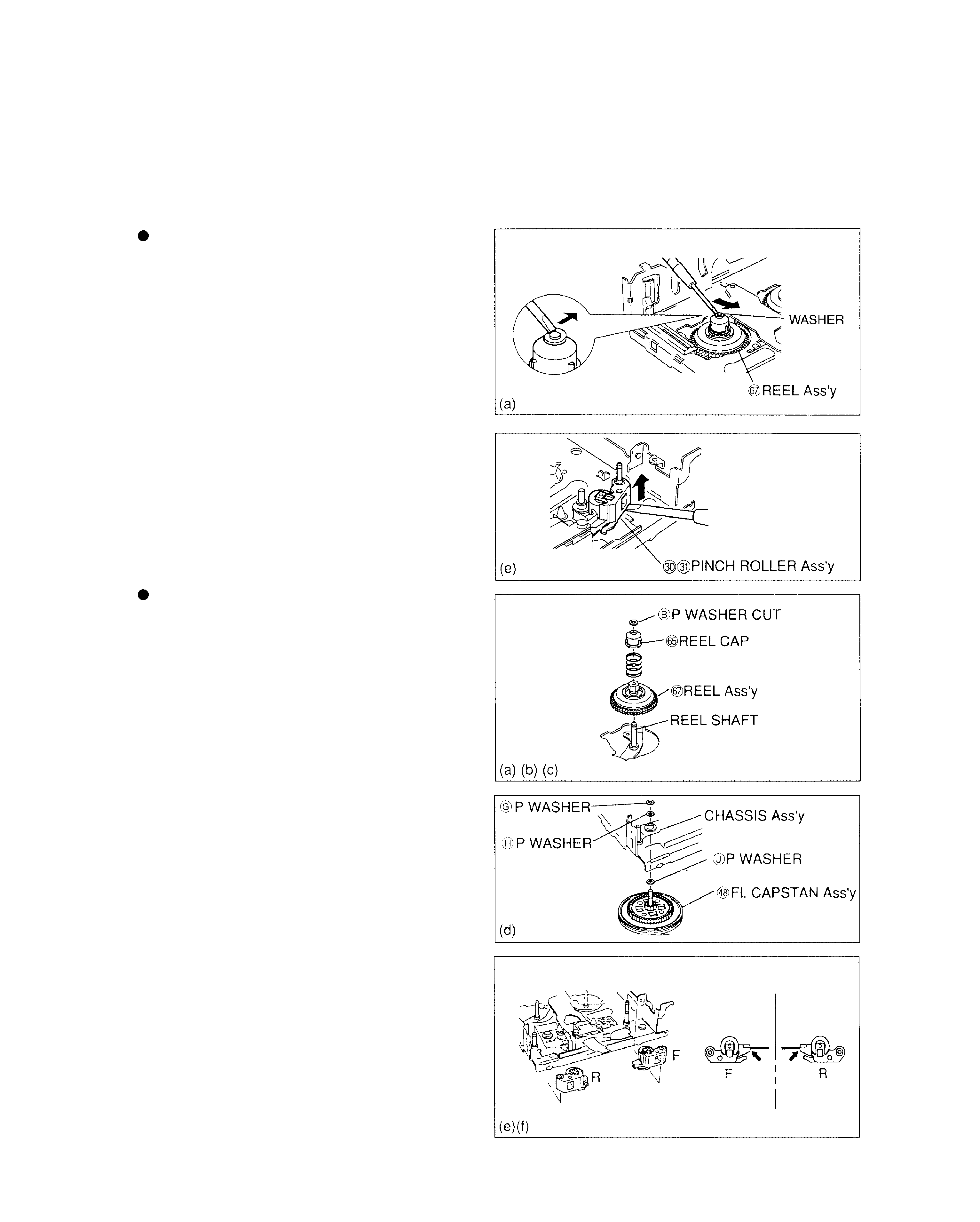
Disassembling
(a) Open and remove the Washer at the lead edge of
...REEL Ass'y as shown in figure. (The washer is dam-
ageable, and it cannot be reused.)
(b) Raise and remove
:REEL CAP/REEL Ass'y.
(c) For
,FL CAPSTAN Ass'y, open and remove the Washer
in the same manner.
(d) Remove the FL CAPSTAN Ass'y from the bottom (In
such a case,
HJP WASHERS may stay on the Chassis,
and take care not to allow them to enter the deck.) (See
Fig.(d) in next item)
(e) Insert a flat-head screwdriver into
§PINCH ROLLER
Ass'y as shown in figure, and raise the Ass'y until it
clicks. Thus, it will be unlocked.
(f) Then, remove the Pinch Roller Ass'y by hand.
Reassembling
(a) Insert the
...REEL Ass'y into the REEL SHAFT.
(b) Insert
"REEL WING SPRING, then a :REEL CAP on
it, and push them until they pass through the REEL
SHAFT.
(c) Under this condition, insert
BP WASHER CUT.
(d) Insert the
,FL CAPSTAN Ass'y into the CHASSIS Ass'y
and lock with
GP WASHER (At this time, don't forget to
insert
HJP WASHERS.)
(e) The PINCH ROLLER Ass'y is designed so as to be fit by
a force, and therefore insert it into the SHAFT of
1CHASSIS Ass'y at portions F and R.
(f) The PINCH ROLLER Ass'y is designed so as to be fit by
a force, and therefore insert it into the SHAFT of
1CHASSIS Ass'y at portions F and R. Next, press to fit
the Springs attaching to
@HEAD PANEL Ass'y at both F
and R in the same manner.
1.4.
REEL Ass'y/,FL CAPSTAN Ass'y/§PINCH ROLLER Ass'y
CAUTION:
As
:REEL CAP/§PINCH ROLLER Ass'y are damageable during disassembling, they cannot be reused.