SERVICE MANUAL
DVD AUDIO/VIDEO PLAYER
No.A0016
Jul. 2001
COPYRIGHT
2001 VICTOR COMPANY OF JAPAN, LTD.
XV-SA70BK / XV-SA75GD
XV-SA70BK/XV-SA75GD
Area Suffix
(XV-SA70BK)
J ------------- U.S.A.
C ---------- Canada
Area Suffix
(XV-SA75GD)
J ------------- U.S.A.
This service manual is printed on 100% recycled paper.
Contents
Safety precautions ------------------------ 1-2
Preventing static electricity ------------- 1-3
Importance admistering
point on the safety ------------ 1-4
Precautions for service ----------------- 1-5
Disassembly method -------------------- 1-6
Adjustment method ---------------------- 1-15
Troubleshooting -------------------------- 1-19
Description of major ICs ---------------- 1-23
Glossary of term and abbreviations -- 1-43
Model
XV-SA70BK
XV-SA75GD
Body color
Black
Gold
Each difference point
STANDBY/ON
STANDBY/ON
PAUSE
PLAY
STOP
SKIP
OPEN/CLOSE
PROGRESSIVE
DVD AUDIO
DVD/VIDEO CD/CD
XV-SA70 DVD AUDIO/DVD VIDEO/CD PLAYER
PROGRESSIVE
SCAN
S.FREQ
OPEN
/CLOSE
TV
DVD
TV
DVD
STANDBY/ON
REPEAT
123
56
89
0
+10
10
7
4
3D
PHONIC
TV/VIDEO
CANCEL
SUBTITLE
ANGLE
TV1
TV2
TV3
TV4
TV5
TV6
TV7
TV8
TV9
TV -/--
TV0
MUTING
AUDIO
VFP
DIGEST
PAGE
PREVIO
US
NEXT
CLEAR
STROBE
SLOW+
SLOW
-
TO
P
ME
NU
MEN
U
CHOI
CE
ENTER
RM-SXVM50J REMOTE CONTROL
CH+
SELECT
CH-
VOL
+
VOL
-
ON
SCR
EEN
ZOOM
+
-
RETURN
XV-SA70BK/XV-SA75GD
1-2
1. This design of this product contains special hardware and many circuits and components specially for safety
purposes. For continued protection, no changes should be made to the original design unless authorized in
writing by the manufacturer. Replacement parts must be identical to those used in the original circuits. Services
should be performed by qualified personnel only.
2. Alterations of the design or circuitry of the product should not be made. Any design alterations of the product
should not be made. Any design alterations or additions will void the manufacturer`s warranty and will further
relieve the manufacture of responsibility for personal injury or property damage resulting therefrom.
3. Many electrical and mechanical parts in the products have special safety-related characteristics. These
characteristics are often not evident from visual inspection nor can the protection afforded by them necessarily
be obtained by using replacement components rated for higher voltage, wattage, etc. Replacement parts which
have these special safety characteristics are identified in the Parts List of Service Manual. Electrical
components having such features are identified by shading on the schematics and by (
) on the Parts List in
the Service Manual. The use of a substitute replacement which does not have the same safety characteristics
as the recommended replacement parts shown in the Parts List of Service Manual may create shock, fire, or
other hazards.
4. The leads in the products are routed and dressed with ties, clamps, tubings, barriers and the like to be
separated from live parts, high temperature parts, moving parts and/or sharp edges for the prevention of
electric shock and fire hazard. When service is required, the original lead routing and dress should be
observed, and it should be confirmed that they have been returned to normal, after re-assembling.
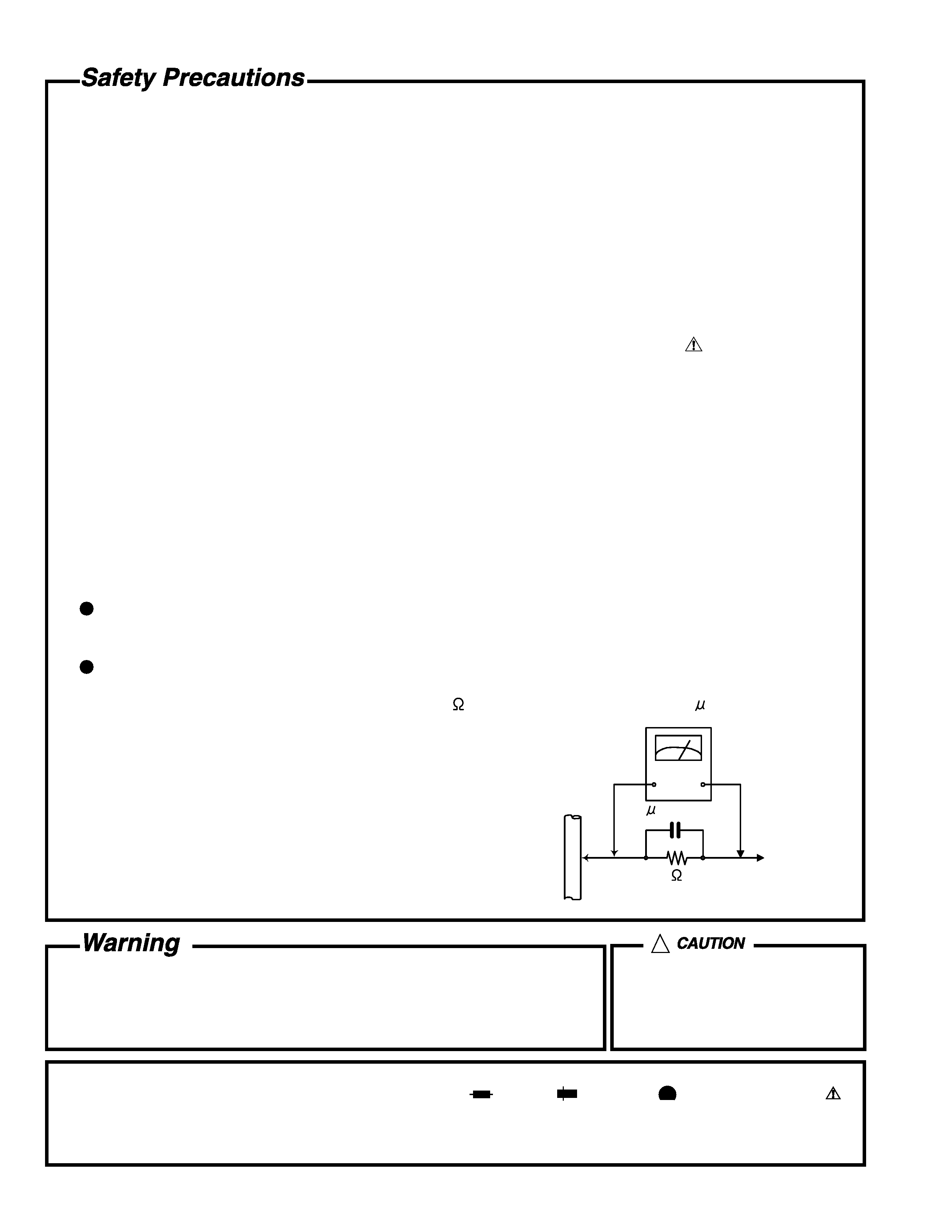
5. Leakage current check (Electrical shock hazard testing)
After re-assembling the product, always perform an isolation check on the exposed metal parts of the product
(antenna terminals, knobs, metal cabinet, screw heads, headphone jack, control shafts, etc.) to be sure the
product is safe to operate without danger of electrical shock.
Do not use a line isolation transformer during this check.
Plug the AC line cord directly into the AC outlet. Using a "Leakage Current Tester", measure the leakage
current from each exposed metal parts of the cabinet, particularly any exposed metal part having a return
path to the chassis, to a known good earth ground. Any leakage current must not exceed 0.5mA AC (r.m.s.).
Alternate check method
Plug the AC line cord directly into the AC outlet. Use an AC voltmeter having, 1,000 ohms per volt or more
sensitivity in the following manner. Connect a 1,500
10W resistor paralleled by a 0.15 F AC-type capacitor
between an exposed metal part and a known good earth ground.
Measure the AC voltage across the resistor with the AC
voltmeter.
Move the resistor connection to each exposed metal part,
particularly any exposed metal part having a return path to
the chassis, and measure the AC voltage across the resistor.
Now, reverse the plug in the AC outlet and repeat each
measurement. Voltage measured any must not exceed 0.75 V
AC (r.m.s.). This corresponds to 0.5 mA AC (r.m.s.).
1. This equipment has been designed and manufactured to meet international safety standards.
2. It is the legal responsibility of the repairer to ensure that these safety standards are maintained.
3. Repairs must be made in accordance with the relevant safety standards.
4. It is essential that safety critical components are replaced by approved parts.
5. If mains voltage selector is provided, check setting for local voltage.
Good earth ground
Place this
probe on
each exposed
metal part.
AC VOLTMETER
(Having 1000
ohms/volts,
or more sensitivity)
1500
10W
0.15 F AC TYPE
!
Burrs formed during molding may
be left over on some parts of the
chassis. Therefore, pay attention to
such burrs in the case of
preforming repair of this system.
In regard with component parts appearing on the silk-screen printed side (parts side) of the PWB diagrams, the
parts that are printed over with black such as the resistor (
), diode (
) and ICP (
) or identified by the " "
mark nearby are critical for safety.
When replacing them, be sure to use the parts of the same type and rating as specified by the manufacturer.
(Except the J and C version)
XV-SA70BK/XV-SA75GD
1-3
Preventing static electricity
Electrostatic discharge (ESD), which occurs when static electricity stored in the body, fabric, etc. is discharged,
can destroy the laser diode in the traverse unit (optical pickup). Take care to prevent this when performing repairs.
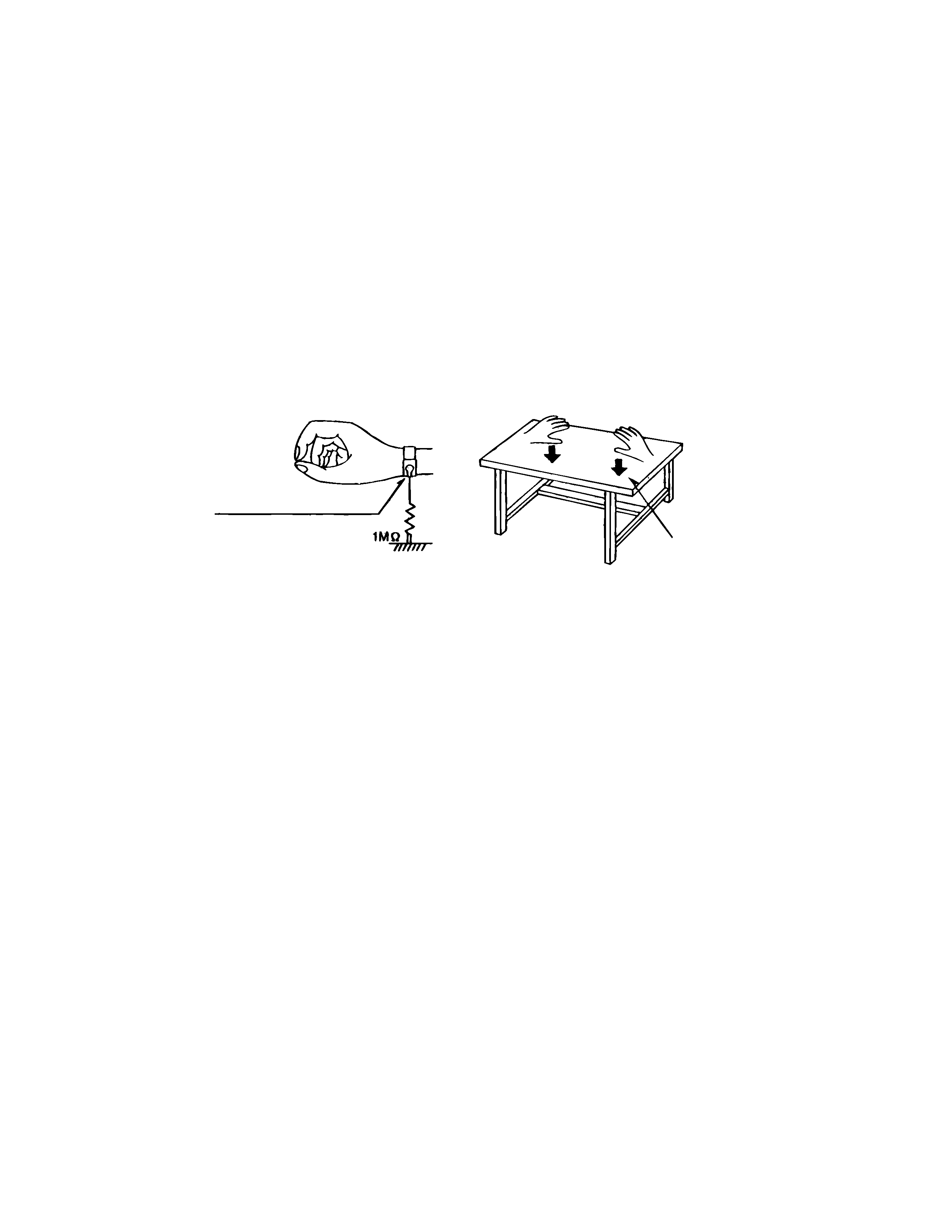
1.1. Grounding to prevent damage by static electricity
Static electricity in the work area can destroy the optical pickup (laser diode) in devices such as DVD players.
Be careful to use proper grounding in the area where repairs are being performed.
1.1.1. Ground the workbench
1. Ground the workbench by laying conductive material (such as a conductive sheet) or an iron plate over
it before placing the traverse unit (optical pickup) on it.
1.1.2. Ground yourself
1. Use an anti-static wrist strap to release any static electricity built up in your body.
1.1.3. Handling the optical pickup
1. In order to maintain quality during transport and before installation, both sides of the laser diode on the
replacement optical pickup are shorted. After replacement, return the shorted parts to their original condition.
(Refer to the text.)
2. Do not use a tester to check the condition of the laser diode in the optical pickup. The tester's internal power
source can easily destroy the laser diode.
1.2. Handling the traverse unit (optical pickup)
1. Do not subject the traverse unit (optical pickup) to strong shocks, as it is a sensitive, complex unit.
2. Cut off the shorted part of the flexible cable using nippers, etc. after replacing the optical pickup. For specific
details, refer to the replacement procedure in the text. Remove the anti-static pin when replacing the traverse
unit. Be careful not to take too long a time when attaching it to the connector.
3. Handle the flexible cable carefully as it may break when subjected to strong force.
4. It is not possible to adjust the semi-fixed resistor that adjusts the laser power. Do not turn it
Conductive material
(conductive sheet) or iron plate
(caption)
Anti-static wrist strap
XV-SA70BK/XV-SA75GD
1-4
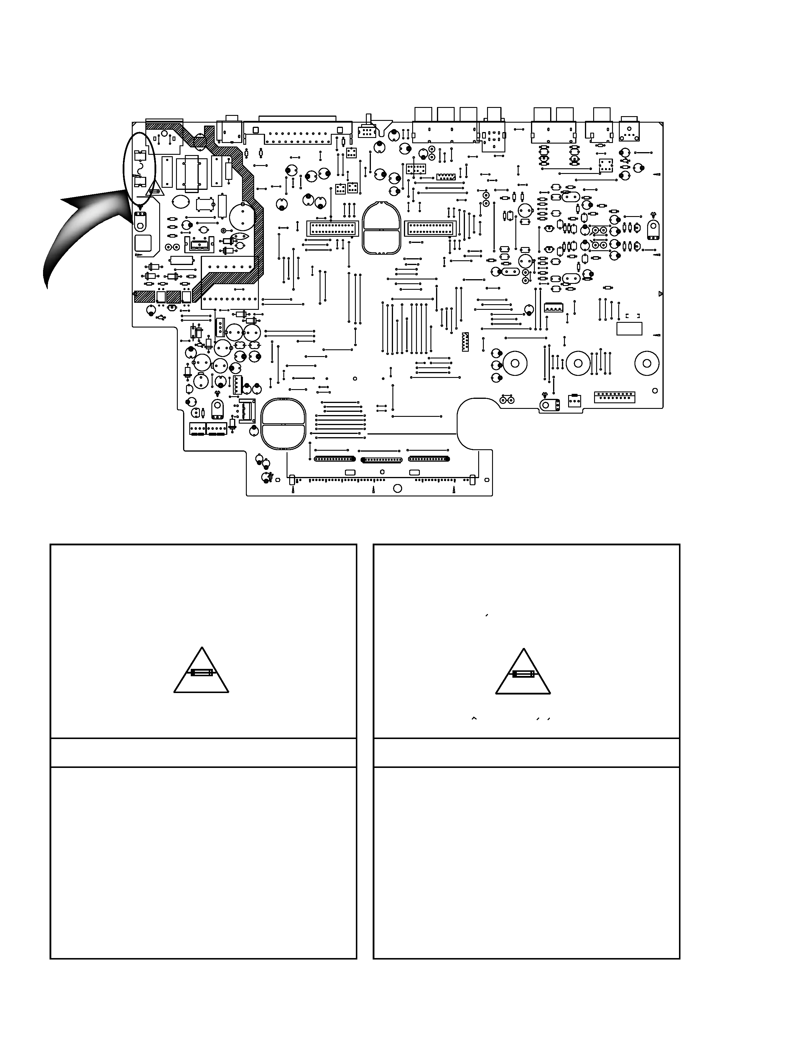
Full Fuse Replacement Marking
Graphic symbol mark
(This symbol means fast blow type fuse.)
should be read as follows ;
FUSE CAUTION
FOR CONTINUED PROTECTION AGAINST RISK
OF FIRE, REPLACE ONLY WITH SAME TYPE
AND RATING OF FUSES ;
F901 : 1.6 A / 125 V
F901 : 1.6 A / 125 V
Marquage Pour Le Remplacement
Complet De Fusible
PRECAUTIONS SUR LES FUSIBLES
POUR UNE PROTECTION CONTINUE CONTRE
DES RISQUES D'INCENDIE, REMPLACER
SEULEMENT PAR UN FUSIBLE DU MEME TYPE ;
Le symbole graphique (Ce symbole signifie
fusible de type a fusion rapide.)
doit etre interprete comme suit ;
Importance Admistering point on the Safety
F901
1.6A/125V
B1
B2
B4
B3
R992
D992
EP902
B517
B516
B13
B14
C1
C2
C5
C8
C111
C707
C711
C714
C715
C716
C717
C721
C730
C731
C737
C738
C740
C741
C742
C743
C744
C745
C746
C747
C750
C751
C752
C753
C754
C755
C756
C757
C761
C762
C771
C772
C801
C806
C807
C808
C809
C810
C812
C813
C814
C815
C816
C817
C818
C902
C903
C905
C906
C907
C908
C909
C913
C914
C918
C960
C962
C963
C965
C966
C969
C973
C978
C979
C982
C984
C987
C989
C992
C997
C1701
C1702
CN3
CN512
CN513
CN701
CN801
CP951
B319
B320
B216
B75
D702
D901
D902
D903
D904
D908
D910
HS952
B78
D950
D951
D952
D953
D954
D956
D957
D960
D991
DI1
EP711
EP951
FC902
FC901
IC901
IC951
IC952
J700
J701
J702
J703
J801
J802
J804
JT102
JT202
K801
K902
L709
L710
L801
L802
L803
L804
L901
L952
L955
L957
L959
P901
PC901
PC902
B77
Q743
Q744
Q753
Q754
Q755
Q756
Q951
Q991
R711
R712
R713
R715
R726
R731
R740
R741
R742
R743
R1500
R746
R748
R750
R751
R752
R753
R1501
R756
R758
R761
R762
R764
R765
R766
R767
R771
R772
R774
R775
R776
R777
R780
R781
R782
R783
R790
R791
R792
R793
R797
R818
R901
R903
R904
R905
R906
R907
R908
R910
R911
R920
R956
R1721
RA1
RA2
RA3
S801
T901
T1701
B15
B16
B17
B18
B19
B20
B21
B22
B12
B24
B25
B26
B27
B28
B29
B30
B31
B32
B33
B34
B35
B36
B37
B38
B39
B80
B40
B41
B42
B43
B515
B45
B46
B48
B49
B50
B55
B54
B229
B56
B57
B58
B875
B61
B62
B63
B64
B65
B66
B67
B69
B101
B102
B103
B104
B105
B106
B107
B108
B109
B110
B111
B112
B113
B114
B115
C748
B118
B119
C749
B122
B123
B125
B126
B127
B128
B129
B130
B131
B132
B133
B79
B202
B203
B204
B205
B206
B207
B208
B209
B212
B215
B218
B219
B220
B223
B224
B225
B226
B301
B302
B303
HS901
B81
B304
B305
B306
B307
B308
B309
B311
B313
B314
B315
B316
B317
B318
B321
B322
B323
B324
B325
B326
B327
B328
B329
B611
C700
B402
B403
B404
B405
B406
C703
IC701
B408
B409
B410
B411
B412
B413
B414
B415
B416
B417
B418
B419
B420
B501
B502
B503
B504
B505
B506
B507
B508
B509
B510
B511
B512
B513
B514
B602
B603
B604
B605
B606
B607
B608
B610
B601
B701
B702
B703
CN802
B874
B753
B754
B755
B756
B757
B758
B759
B760
EP901
B852
B853
B854
B855
B856
B857
B858
B859
B860
B861
B862
B863
B864
B865
B866
B867
B868
B869
B870
B871
B872
B873
B330
B227
B705
B706
B422
C1800
B310
K707
K708
K709
K710
B82
K711
XV-SA70BK/XV-SA75GD
1-5
Precautions for Service
Handling of Traverse Unit and Laser Pickup
1. Do not touch any peripheral element of the pickup or the actuator.
2. The traverse unit and the pickup are precision devices and therefore must not be subjected to
strong shock.
3. Do not use a tester to examine the laser diode. (The diode can easily be destroyed by the
internal power supply of the tester.)
4. To replace the traverse unit, pull out the metal short pin for protection from charging.
5. When replacing the pickup, after mounting a new pickup, remove the solder on the short land
which is provided at the center of the flexible wire to open the circuit.
6. Half-fixed resistors for laser power adjustment are adjusted in pairs at shipment to match the
characteristics of the optical block.
Do not change the setting of these half-fixed resistors for laser power adjustment.
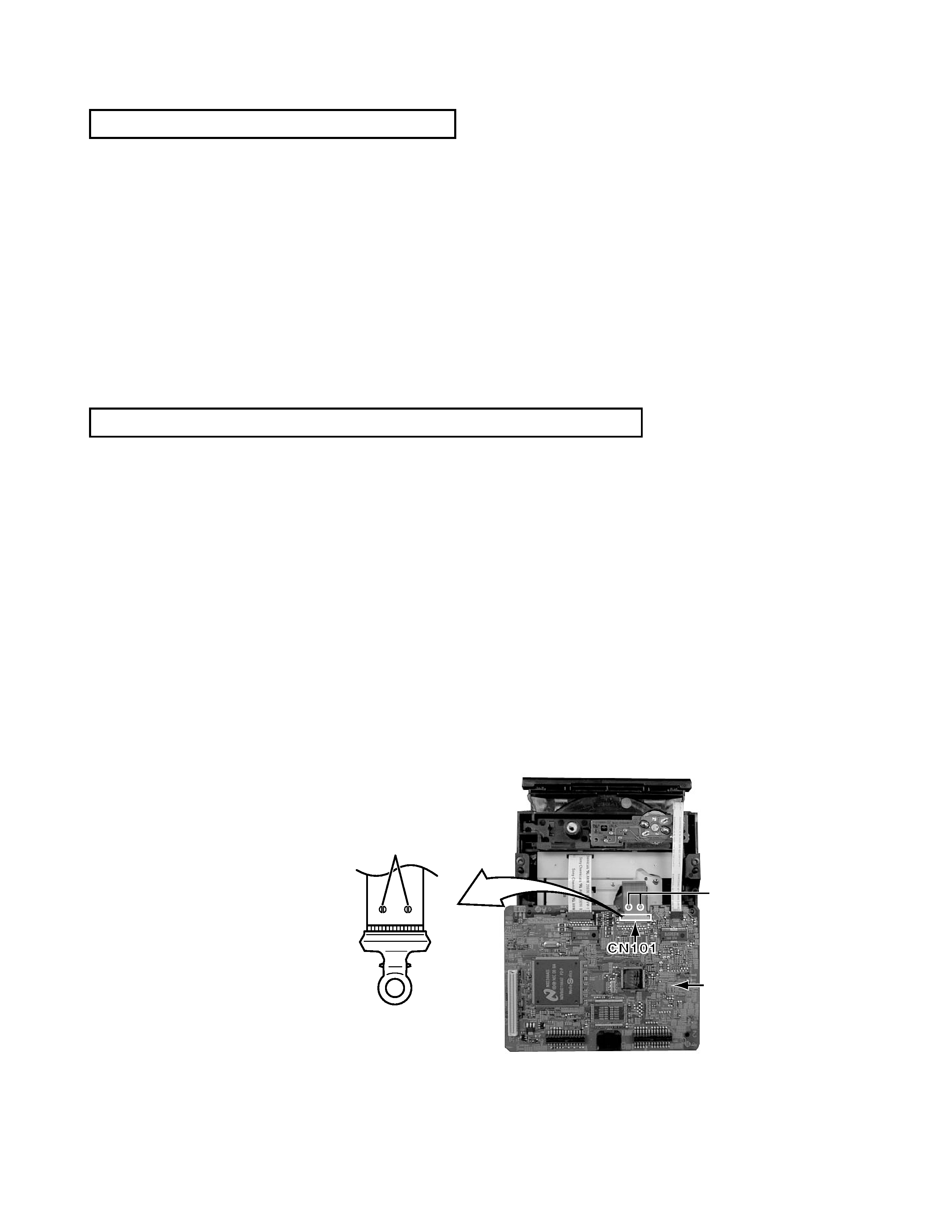
Destruction of Traverse Unit and Laser Pickup by Static Electricity
Laser diodes are easily destroyed by static electricity charged on clothing
or the human body. Before repairing peripheral elements of the traverse
unit or pickup, be sure to take the following electrostatic protection:
1. Wear an antistatic wrist wrap.
2. With a conductive sheet or a steel plate on the workbench on which
the traverse unit or the pick up is to be repaired, ground the sheet
or the plate.
3. After removing the flexible wire from the connector (CN101),
short-circuit the flexible wire by the metal clip.
4. Short-circuit the laser diode by soldering the land which is provided
at the center of the flexible wire for the pickup.
After completing the repair, remove the solder
to open the circuit.
Please refer to "Fig.5" of "Disassembly
method" for details.
Servo control
board
Short circuit
Short circuit