SERVICE MANUAL
COPYRIGHT © 2005 Victor Company of Japan, Limited
No.YD053
2005/2
DVD PLAYER
YD053
2005
2
XV-N320B,XV-N322S
TABLE OF CONTENTS
1
PRECAUTION. . . . . . . . . . . . . . . . . . . . . . . . . . . . . . . . . . . . . . . . . . . . . . . . . . . . . . . . . . . . . . . . . . . . . . . . . 1-3
2
SPECIFIC SERVICE INSTRUCTIONS . . . . . . . . . . . . . . . . . . . . . . . . . . . . . . . . . . . . . . . . . . . . . . . . . . . . . . 1-7
3
DISASSEMBLY . . . . . . . . . . . . . . . . . . . . . . . . . . . . . . . . . . . . . . . . . . . . . . . . . . . . . . . . . . . . . . . . . . . . . . . 1-8
4
ADJUSTMENT . . . . . . . . . . . . . . . . . . . . . . . . . . . . . . . . . . . . . . . . . . . . . . . . . . . . . . . . . . . . . . . . . . . . . . . 1-15
5
TROUBLESHOOTING . . . . . . . . . . . . . . . . . . . . . . . . . . . . . . . . . . . . . . . . . . . . . . . . . . . . . . . . . . . . . . . . . 1-18
Area Suffix
US ----------------------- U.S.A.
UC ------------------- Canada
XV-N320BUSC,XV-N320BUCC,XV-N322SUSC,XV-N322SUCC
VIDEO
®
OPEN/
CLOSE
LIST
SET UP
CLEAR
SLOW +
DISPLAY ON SCREEN
ENTER
STANDBY/ON
VFP
I/P
CANCEL
RETURN
SOUND
EFFECT
TITLE/
GROUP
DIMMER
AUDIO
SUBTITLE
ANGLE
SLIDE EFFECT
ZOOM
12
3
45
6
78
9
0
THUMBNAIL/
TOP
MENU
MENU
NEXT
PREVIOUS
SELECT

1-2 (No.YD053)
SPECIFICATION
XV-N320B,XV-N322S for US,UC
General
Readable discs
DVD VIDEO, DVD-R (Video format), DVD-RW (Video format), SVCD, Video CD, Audio CD (CD-DA),
CD-R/RW (CD-DA, SVCD, Video CD, MP3 format, JPEG)
Video format
NTSC, 480i/480p selectable
Other
Power requirements
AC 120 V~, 60 Hz
Power consumption
11.0 W (POWER ON), 1.0 W (STANDBY mode)
Mass
1.5 kg (3.3 lbs)
Dimensions (W
× H × D)
435mm
× 44mm × 201.5 mm (17-3/16 inch × 1-3/4 inc × 7-15/16 inch)
Video outputs
COMPONENT (pin jacks)
Y Output: 1.0 Vp-p (75
)
Pb/Pr Output: 0.7Vp-p (75
)
VIDEO (pin jack)
1.0 Vp-p (75
)
S-VIDEO (S jack)
Y Output: 1.0 Vp-p (75
)
C Output: 286 mVp-p (75
)
Horizontal resolution
500 lines or more
Audio outputs
ANALOG OUT (pin jack)
2.0 Vrms (10 k
)
DIGITAL OUT (COAXIAL) 0.5 Vp-p (75
termination)
Audio characteristics
Frequency response
CD (sampling frequency 44.1 kHz):2 Hz to 20 kHz
DVD (sampling frequency 48 kHz):2 Hz to 22 kHz
(4 Hz to 20 kHz for DTS and Dolby Digital bitstream signals)
DVD (sampling frequency 96 kHz):2 Hz to 44 kHz
Wow and flutter
Unmeasurable (less than +- 0.002%)
Total harmonic distortion
less than 0.009%
(No.YD053)1-3
SECTION 1
PRECAUTION
1.1
Safety Precautions
(1) This design of this product contains special hardware and
many circuits and components specially for safety purpos-
es. For continued protection, no changes should be made
to the original design unless authorized in writing by the
manufacturer. Replacement parts must be identical to
those used in the original circuits. Services should be per-
formed by qualified personnel only.
(2) Alterations of the design or circuitry of the product should
not be made. Any design alterations of the product should
not be made. Any design alterations or additions will void
the manufacturers warranty and will further relieve the
manufacture of responsibility for personal injury or property
damage resulting therefrom.
(3) Many electrical and mechanical parts in the products have
special safety-related characteristics. These characteris-
tics are often not evident from visual inspection nor can the
protection afforded by them necessarily be obtained by us-
ing replacement components rated for higher voltage, watt-
age, etc. Replacement parts which have these special
safety characteristics are identified in the Parts List of Ser-
vice Manual. Electrical components having such features
are identified by shading on the schematics and by (
) on
the Parts List in the Service Manual. The use of a substitute
replacement which does not have the same safety charac-
teristics as the recommended replacement parts shown in
the Parts List of Service Manual may create shock, fire, or
other hazards.
(4) The leads in the products are routed and dressed with ties,
clamps, tubings, barriers and the like to be separated from
live parts, high temperature parts, moving parts and/or
sharp edges for the prevention of electric shock and fire
hazard. When service is required, the original lead routing
and dress should be observed, and it should be confirmed
that they have been returned to normal, after reassem-
bling.
(5) Leakage shock hazard testing)
After reassembling the product, always perform an isola-
tion check on the exposed metal parts of the product (an-
tenna terminals, knobs, metal cabinet, screw heads,
headphone jack, control shafts, etc.) to be sure the product
is safe to operate without danger of electrical shock.Do not
use a line isolation transformer during this check.
· Plug the AC line cord directly into the AC outlet. Using a
"Leakage Current Tester", measure the leakage current
from each exposed metal parts of the cabinet, particular-
ly any exposed metal part having a return path to the
chassis, to a known good earth ground. Any leakage cur-
rent must not exceed 0.5mA AC (r.m.s.).
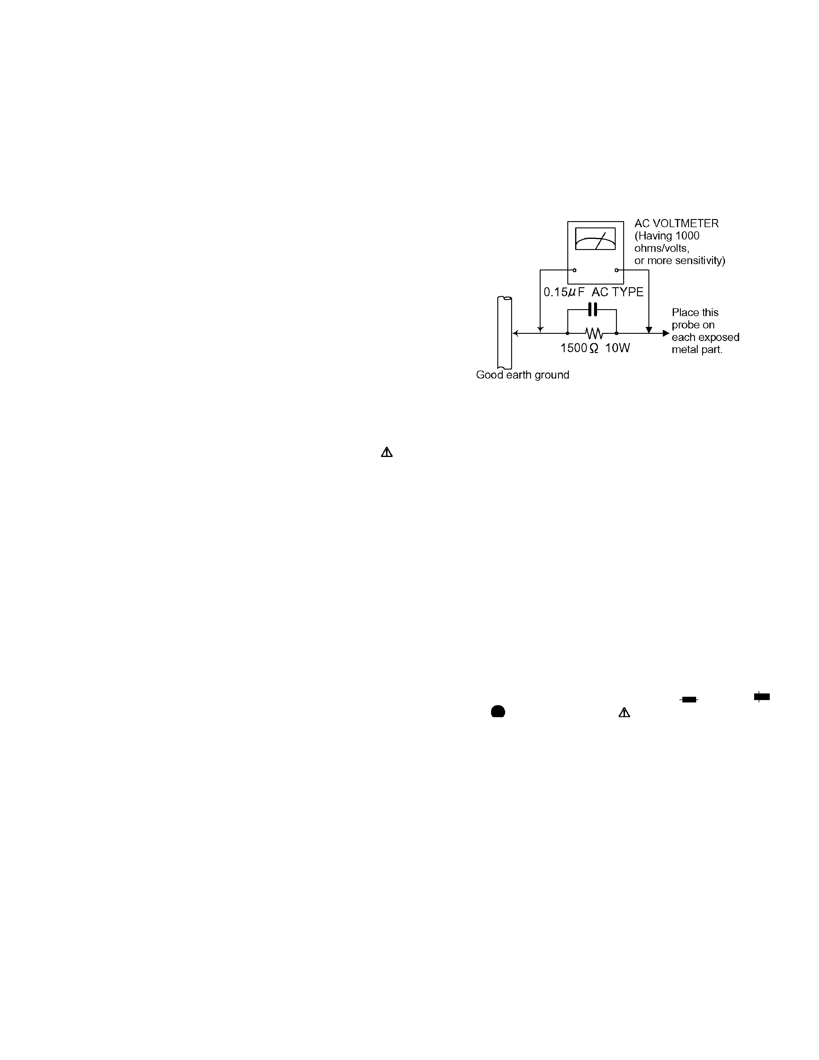
· Alternate check method
Plug the AC line cord directly into the AC outlet. Use an
AC voltmeter having, 1,000 ohms per volt or more sensi-
tivity in the following manner. Connect a 1,500 ohm 10W
resistor paralleled by a 0.15 F AC-type capacitor be-
tween an exposed metal part and a known good earth
ground.
Measure the AC voltage across the resistor with the AC
voltmeter.
Move the resistor connection to each exposed metal
part, particularly any exposed metal part having a return
path to the chassis, and measure the AC voltage across
the resistor. Now, reverse the plug in the AC outlet and
repeat each measurement. Voltage measured any must
not exceed 0.75 V AC (r.m.s.). This corresponds to 0.5
mA AC (r.m.s.).
1.2
Warning
(1) This equipment has been designed and manufactured to
meet international safety standards.
(2) It is the legal responsibility of the repairer to ensure that
these safety standards are maintained.
(3) Repairs must be made in accordance with the relevant
safety standards.
(4) It is essential that safety critical components are replaced
by approved parts.
(5) If mains voltage selector is provided, check setting for local
voltage.
1.3
Caution
Burrs formed during molding may be left over on some parts
of the chassis.
Therefore, pay attention to such burrs in the case of pre-
forming repair of this system.
1.4
Critical parts for safety
In regard with component parts appearing on the silk-screen
printed side (parts side) of the PWB diagrams, the parts that are
printed over with black such as the resistor (
), diode (
)
and ICP (
) or identified by the " " mark nearby are critical for
safety. When replacing them, be sure to use the parts of the
same type and rating as specified by the manufacturer. (Except
the JC version)
1-4 (No.YD053)
1.5
Preventing static electricity
Electrostatic discharge (ESD), which occurs when static electricity stored in the body, fabric, etc. is discharged, can destroy the laser
diode in the traverse unit (optical pickup). Take care to prevent this when performing repairs.
1.5.1
Grounding to prevent damage by static electricity
Static electricity in the work area can destroy the optical pickup (laser diode) in devices such as DVD players.
Be careful to use proper grounding in the area where repairs are being performed.
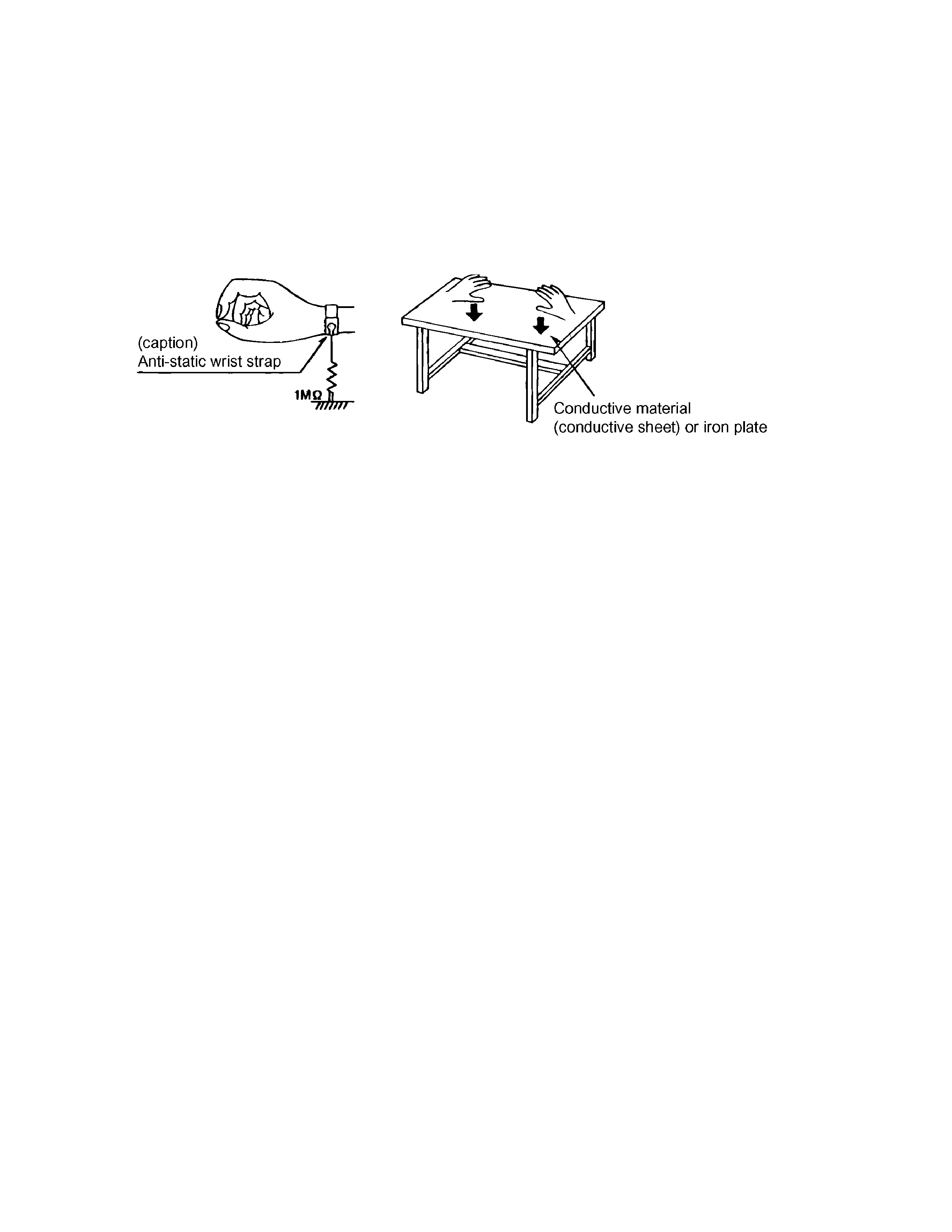
(1) Ground the workbench
Ground the workbench by laying conductive material (such as a conductive sheet) or an iron plate over it before placing the
traverse unit (optical pickup) on it.
(2) Ground yourself
Use an anti-static wrist strap to release any static electricity built up in your body.
(3) Handling the optical pickup
· In order to maintain quality during transport and before installation, both sides of the laser diode on the replacement optical
pickup are shorted. After replacement, return the shorted parts to their original condition.
(Refer to the text.)
· Do not use a tester to check the condition of the laser diode in the optical pickup. The tester's internal power source can easily
destroy the laser diode.
1.6
Handling the traverse unit (optical pickup)
(1) Do not subject the traverse unit (optical pickup) to strong shocks, as it is a sensitive, complex unit.
(2) Cut off the shorted part of the flexible cable using nippers, etc. after replacing the optical pickup. For specific details, refer to the
replacement procedure in the text. Remove the anti-static pin when replacing the traverse unit. Be careful not to take too long
a time when attaching it to the connector.
(3) Handle the flexible cable carefully as it may break when subjected to strong force.
(4) I t is not possible to adjust the semi-fixed resistor that adjusts the laser power. Do not turn it.
1.7
Precautions of the safe use of battery
· Store the battery in a place where children cannot reach.If a child accidentally swallows the battery, consult a doctorimmediately.
· Do not recharge, short, disassemble or heat the battery or dispose of it in a fire.
Doing any of these things may cause the battery to give off heat, crack, or start a fire.
· Do not leave the battery with other metallic materials.Doing this may cause the battery to give off heat, crack, or start a fire.
· When throwing away or saving the battery, wrap it in tape and insulate; otherwise, the battery may start to give off heat, crack, or
start a fire.
· Do not poke the battery with tweezers or similar tools.Doing this may cause the battery to give off heat, crack, or start a fire.
· Dispose of batteries in the proper manner, according to federal, state, and local regulations.
(No.YD053)1-5
1.8
Importance administering point on the safety
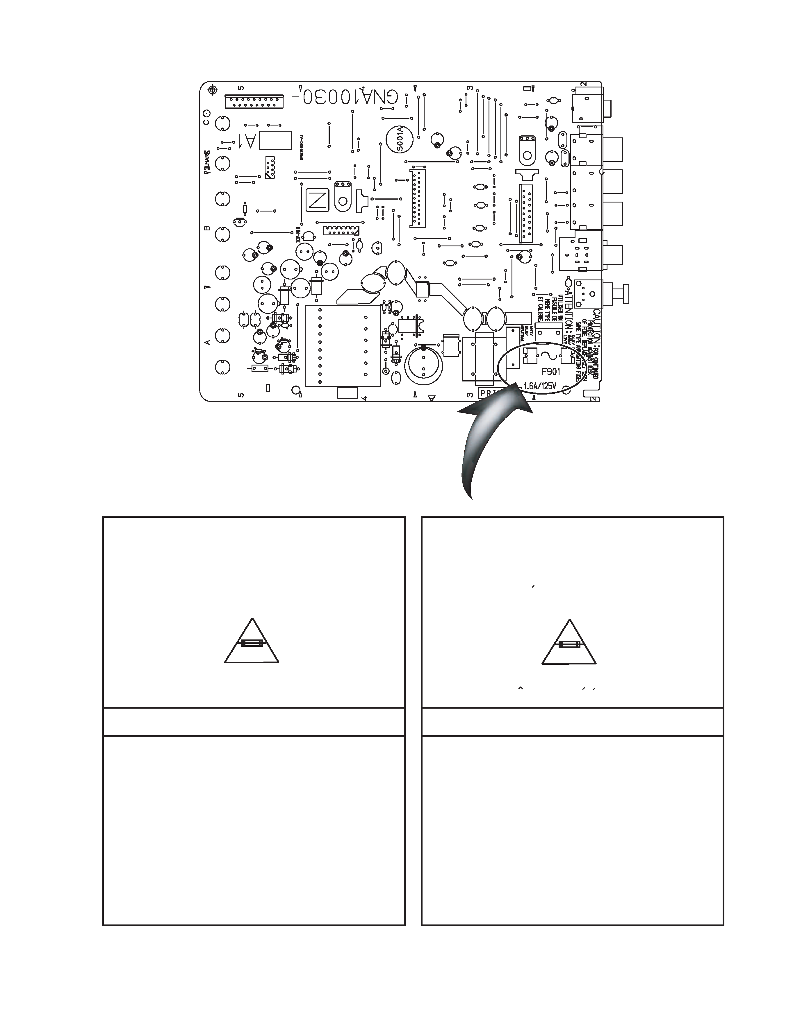
Full Fuse Replacement Marking
Graphic symbol mark
(This symbol means fast blow type fuse.)
should be read as follows ;
FUSE CAUTION
FOR CONTINUED PROTECTION AGAINST RISK
OF FIRE, REPLACE ONLY WITH SAME TYPE
AND RATING OF FUSES ;
F901 : 1.6 A / 125 V
F901 : 1.6 A / 125 V
Marquage Pour Le Remplacement
Complet De Fusible
PRECAUTIONS SUR LES FUSIBLES
POUR UNE PROTECTION CONTINUE CONTRE
DES RISQUES D'INCENDIE, REMPLACER
SEULEMENT PAR UN FUSIBLE DU MEME TYPE ;
Le symbole graphique (Ce symbole signifie
fusible de type a fusion rapide.)
doit etre interprete comme suit ;
B905
C706
C707
C712
C713
C730
B724
C901
C902
C903
C904
C905
C906
C907
C908
C909
C950
C954
C955
C956
C957
C958
C959
C964
C966
C982
C983
C985
CN901
CN902
CN903
B752
CN905
B916
D902
B915
D906
D951
D952
D953
D954
D955
D956
D957
D960
EP902
FC901
FC902
IC901
IC902
J601
J602
J703
J901
L701
L702
L706
L707
L709
L730
L901
L951
L952
L953
L954
L955
L960
P901
PC901
Q951
B731
B730
R901
R902
R950
S501
S502
S503
S504
S505
S506
S507
S508
B711
T901
B770
B725
L970
B755
B768
B757
D903
C756
C755
B751
B910
R963
B726
B716
B754
B763
B767
B750
B769
B908
B753
B766
B912
B746
B745
B719
B758
B759
B748
B903
B747
B904
B913
B756
B917
B901
B914
B702
B919
B705
B703
B740
B744
B902
B765
B762
B918
B715
D905
B727
B717
B704
B712
B743
B706
B749
B722
B710
B709
B718
B906
B764
B761
B760
CN904
B721
B720
B723
B729
B742
B907
B741
B708
B701
B714
B713
B728
B771
CP950
EP901