SERVICE MANUAL
No.A0001
Contents
Safety precautions
Technical description
Disassembly method
Troubleshooting
Precaution for servicing
1-2
1-3
1-6
1-9
1-13
VICTOR COMPANY OF JAPAN, LIMITED
OPTICAL DISC BUSINESS DIV. PERSONAL & MOBILE NETWORK BUSINESS UNIT
AV & MULTIMEDIA COMPANY 1644, Shimotsuruma, Yamato, Kanagawa 242-8514, Japan
No.A0001
Sep. 2000
COPYRIGHT
2000 VICTOR COMPANY OF JAPAN, LTD.
Printed in Japan
200009 (S)
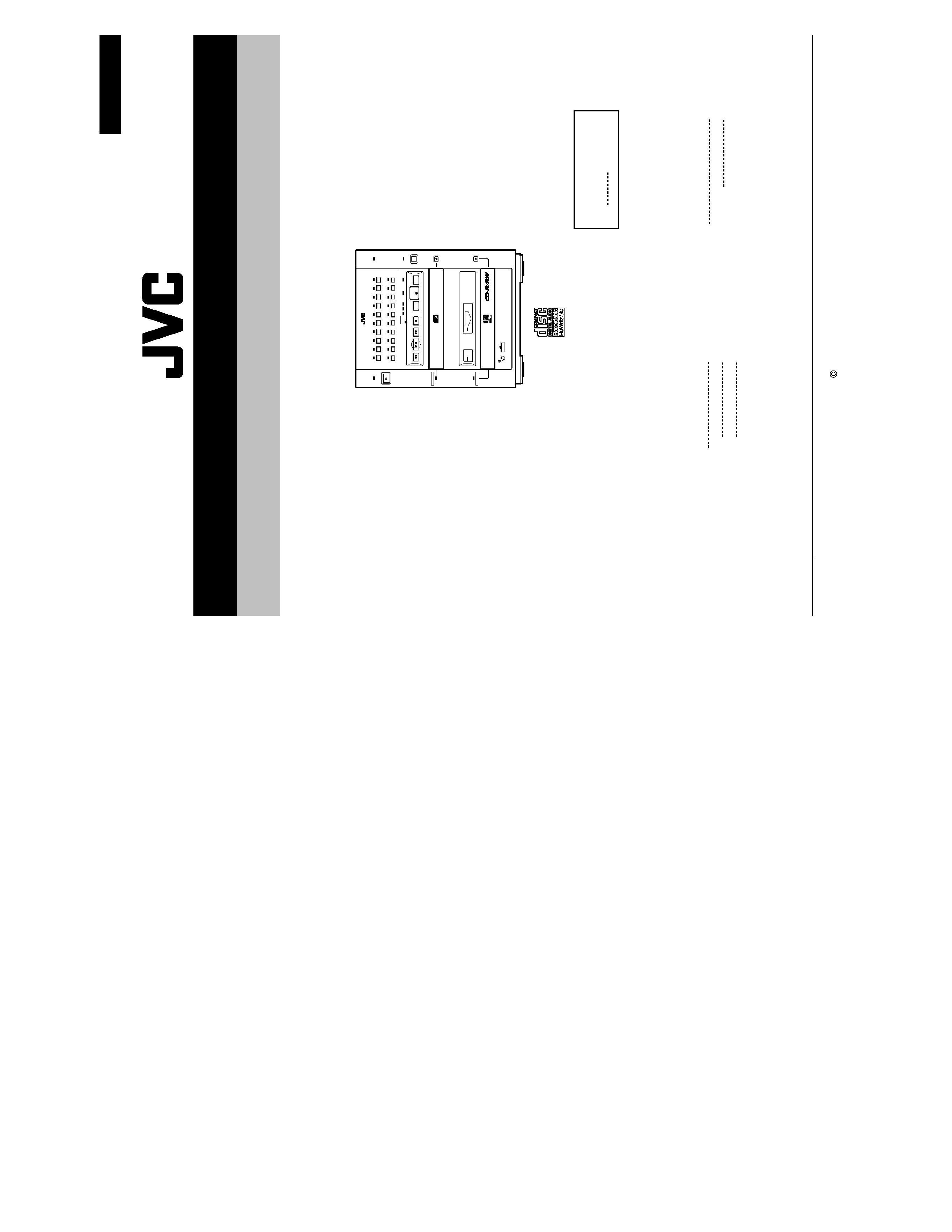
MULTIPLE COMPACT DISC RECORDER
PO
WER
1 TRACK ALL
REPEAT
SPEED
ERASE
OVER
OPEN/CLOSE
SOURCE
SPEED
REPEAT
FINALIZE
PROGRAM
REC
4x 2x 1x
1
11
2
12
3
13
4
14
5
15
6
16
7
17
8
18
9
19
10
20
OPEN/CLOSE
REC/PLAY
SCSI
AUTO REC
XR-D400SL
XR-D400SL
XR-D400SL
E
Germany
Area Suffix
XR-D400SL
1-2
Safety precautions
1. This design of this product contains special hardware and many circuits and components specially
for safety purposes.
For continued protection, no changes should be made to the original design
unless authorized in writing by the manufacturer.
Replacement parts must be identical to those
used in the original circuits.
Services should be performed by qualified personnel only.
2. Alterations of the design or circuitry of the product should not be made.
Any design alterations of
the product should not be made.
Any design alterations or additions will
void the manufacturer`s
warranty and will further relieve the manufacture of responsibility for personal injury or property
damage resulting therefrom.
3. Many electrical and mechanical parts in the products have special safety-related characteristics.
These characteristics are often not evident from visual inspection nor can the protection afforded
by them necessarily be obtained by using replacement components rated for higher voltage,
wattage, etc.
Replacement parts which have these special safety characteristics are identified in
the Parts List of Service Manual.
Electrical components having such features are identified by
shading on the schematics and by (
) on the Parts List in the Service Manual.
The use of a
substitute replacement which does not have the same safety characteristics as the recommended
replacement parts shown in the Parts List of Service Manual may create shock, fire, or other
hazards.
4. The leads in the products are routed and dressed with ties, clamps, tubings, barriers and the
like to be separated from live parts, high temperature parts, moving parts and/or sharp edges
for the prevention of electric shock and fire hazard.
When service is required, the original lead
routing and dress should be observed, and it should be confirmed that they have been returned
to normal, after re-assembling.
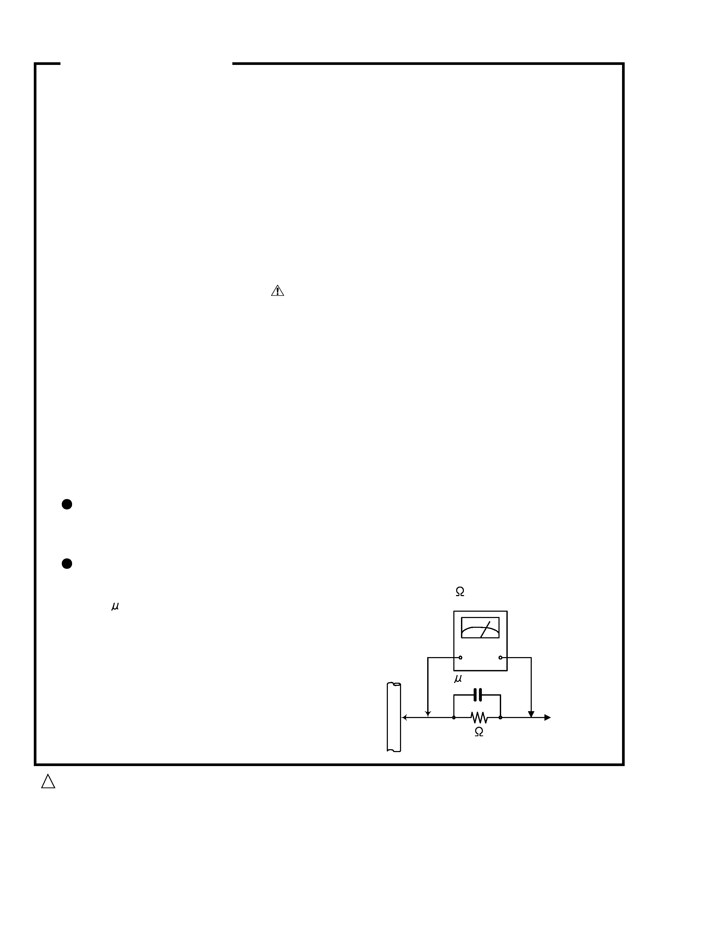
5. Leakage current check (Electrical shock hazard testing)
After re-assembling the product, always perform an isolation check on the exposed metal parts
of the product (antenna terminals, knobs, metal cabinet, screw heads, headphone jack, control
shafts, etc.) to be sure the product is safe to operate without danger of electrical shock.
Do not use a line isolation transformer during this check.
Plug the AC line cord directly into the AC outlet.
Using a "Leakage Current Tester", measure
the leakage
current from each exposed metal parts of the cabinet , particularly any exposed
metal part having a return path to the chassis, to a known good earth ground. Any leakage
current must not exceed 0.5mA AC (r.m.s.)
Alternate check method
Plug the AC line cord directly into the AC outlet.
Use an AC voltmeter having, 1,000 ohms
per volt or more sensitivity in the following manner. Connect a 1,500
10W resistor paralleled by
a 0.15
F AC-type
capacitor
between an
exposed
metal part and a known good earth ground.
Measure the AC voltage across the resistor with the
AC voltmeter.
Move the resistor connection to each exposed metal
part, particularly any exposed metal part having a
return
path
to the
chassis, and measure the
AC
voltage across the resistor. Now reverse the plug in
the AC outlet and repeat each measurement voltage
measured any must not exceed 0.75 V AC (r.m.s.).
This corresponds to 0.5 mA AC (r.m.s.).
Good earth ground
Place this
probe on
each exposed
metal part.
AC VOLTMETER
(Having 1000
ohms/volts,
or more sensitivity)
1500
10W
0.15 F AC TYPE
! CAUTION Burrs formed during molding may be left over on some parts of the chassis. Therefore,
pay attention to such burrs in the case of preforming repair of this system.
XR-D400SL
1-3
Technical description
CD-R/RW recorder for digital audio
CD-R/RW drive for PC
[Fig. 1]
[Fig. 2]
[Table 1] Comparison of Recording and Playback
As its name implies, the XR-D400SL Multiple Compact Disc Recorder provides multiple functions, these
include a CD-R/RW recorder for digital audio and a CD-R/RW drive for a PC.
As the XR-D400SL can be used as a CD-R/RW recorder for digital audio in the dubbing/ recording modes, it is
classified as specific equipment under the private recording royalties system. As a result, discs recorded with
this recorder are distinguished from those recorded with a PC drive.
In the SCSI mode, the XR-D400SL can be used as a CD-R/RW drive for a PC by connecting it through the
SCSI interface. However, it is not possible to use the source disc tray as the dubbing source.
The dubbing source disc tray of the XR-D400SL incorporates a CD-ROM drive and a REC/PLAY disc tray,
which is the dubbing destination and incorporates the CD-R/RW drive (XR-RWD400S) for a PC.
The XR-RWD400S can also be used as a CD-R/RW recorder for digital audio according to the setting of the
control microcomputer.
The XR-RWD400S incorporates a flash memory to facilitate firmware read and write. The firmware is the
program used in controlling the drive.
The use of a flash memory makes it possible to rewrite programs easily.
The recording media royalties are limited to special discs (with a logo mark as shown in Fig. 1) containing the
recording of ID information, which are not recorded in the recording media for PCs.
XR-D400SL
Configuration of the XR-D400SL
CD-R/RW recorder for digital audio
Recording
Playback
CD-R/RW recorder for digital audio
Possible with discs having a logo as in Fig. 1 only
Possible with discs having a logo as in Figs. 1 and 2
CD-R/RW drive for PC
Possible with discs having a logo as in Figs. 1 and 2
Possible with having a logo as in Figs. 1 and 2
XR-D400SL
1-4
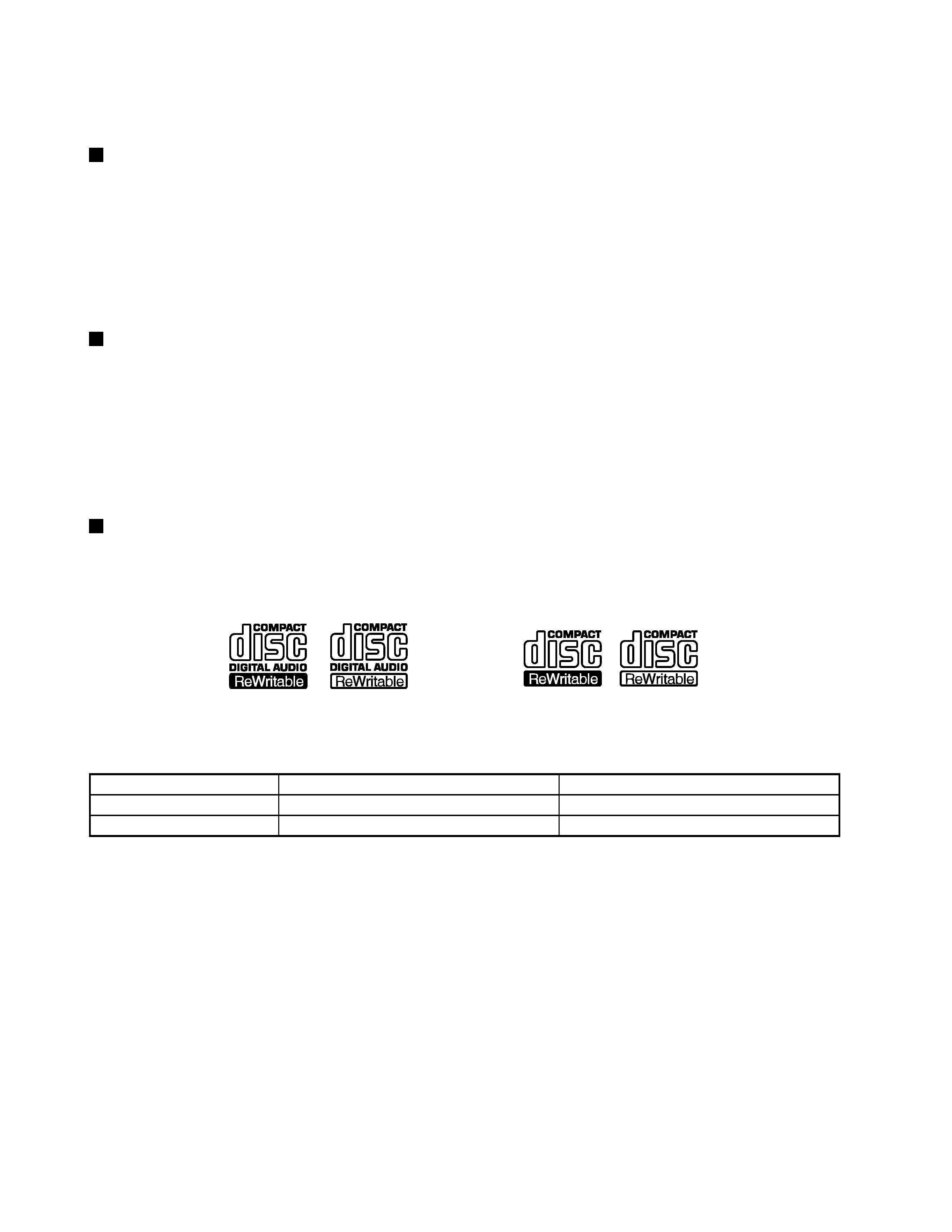
The XR-D400 incorporates the SCMS (Serial Copy Management System) and the RID (Recorder Unique Identifier)
functions.
SCMS is used to limit digital copies to one generation only. The principles are shown in Fig. 3.
With RID, the RID codes are written into discs which are as specified in the Orange Book Parts II and III. The
codes contain the manufacturer's name, product name and machine number to enable the tracing of illegal copies.
Digital recording
Digital recording
[Fig. 3] Principles of SCMS
Fig. 4 shows the structure of a CD-R disc.
In recording, a laser beam having the same wavelength as the
CD beam (780 nm) but of tens times higher power is irradiated
from the substrate surface to the groove.
This irradiation causes thermal deformation of the organic
pigment layer forming pits in it.
The organic pigments include cyanine, phtalocyanine and azoic
dyes and the reflective layer uses gold or silver materials.
In playback the laser beam reads the pits recorded in the
pregroove.
The thermal deformation of the organic pigment layer cannot be
recovered to the original condition. As a result, the CD-R discs
cannot be rewritten and only additional writing is possible with
them.
Fig. 5 shows the structure of a CD-RW disc.
The CD-RW uses a phase-changing recording material in the
recording layer.
With the CD-RW, a laser beam with regulated power and
cooling time is irradiated to form a crystalline phase (erased
status) and amorphous phase (recorded state) on the
polygroove and data is reproduced according to the difference in
reflectivity of the two phases.
An amorphous state can be obtained by quick cooling after
irradiation by a strong laser beam.
The phase-changing recording material is made of a compound
of silver, indium, antimony and tellurium, and rewriting is
possible up to about 1000 times.
As the reflectivity at 780 nm of the CD-RW is lower than the CD-
R, the RF amp gain should be changed in order to play a CD-
RW disc.
SCMS and RID functions
Recording on CD-R discs
Recording on a CD-RW disc
Comparison between the CD-R and the CD-RW
Label printed surface
Protective layer groove
Reflective layer
Organic pigment layer
Substrate
pregroove
Track pitch
1.6
µm
Laser beam
Signal surface
[Fig. 4]
Printed surface
Protective layer
Aluminum reflective layer
Upper protective layer
Recording layer
Lower protective layer
Substrate
polygroove
Signal surface
Laser beam
[Fig. 5]
CD-R
Compact Disc Recordable
CD-RW
Compact Disc Rewritable
Specifications
Laser reflectivity
Recording power
Playback on CD player
Orange Book Part II
65% or more
4 to 11 mW
Possible
Orange Book Part III
15% to 25%
8 to 14 mW
Impossible
[Table 2]
XR-D400SL
1-5
CD-R/RW
CD-R/RW
Lead-in area
This area records the TOC (Table Of Contents) including the number of tracks in the disc, track-start position
information, etc.
Data
This area contains the recording of actual audio signals, file data, etc.
The unit used in the data area is the track. Usually, music CDs use a track per song selection while the CD-
ROM discs basically uses only one track.
Lead-out
This area is used to indicate that the data in the disc has reached the end.
The combination of the lead-in, data and lead-out areas is referred to as a single session.
A disc containing multiple sessions is called a multi-session disc. The CD-EXTRA belongs to this kind of disc.
PCA (Power Calibration Area)
This area is used to regulate the laser power in data writing.
Its data optimizes laser power according to external factors such as the medium type, supply voltage and
operating temperature. The PCA provides an area for use in 99 times of test writing.
PMA (Program Memory Area)
This area contains the recording of the start and end positions of the tracks. When a disc is not finalized in
program recording, this area is used to obtain the preliminary TOC data.
PMA
Track 1
Track 1
Track 1
Track 2
Track 2
Lead-out
PMA
PMA
Lead-in
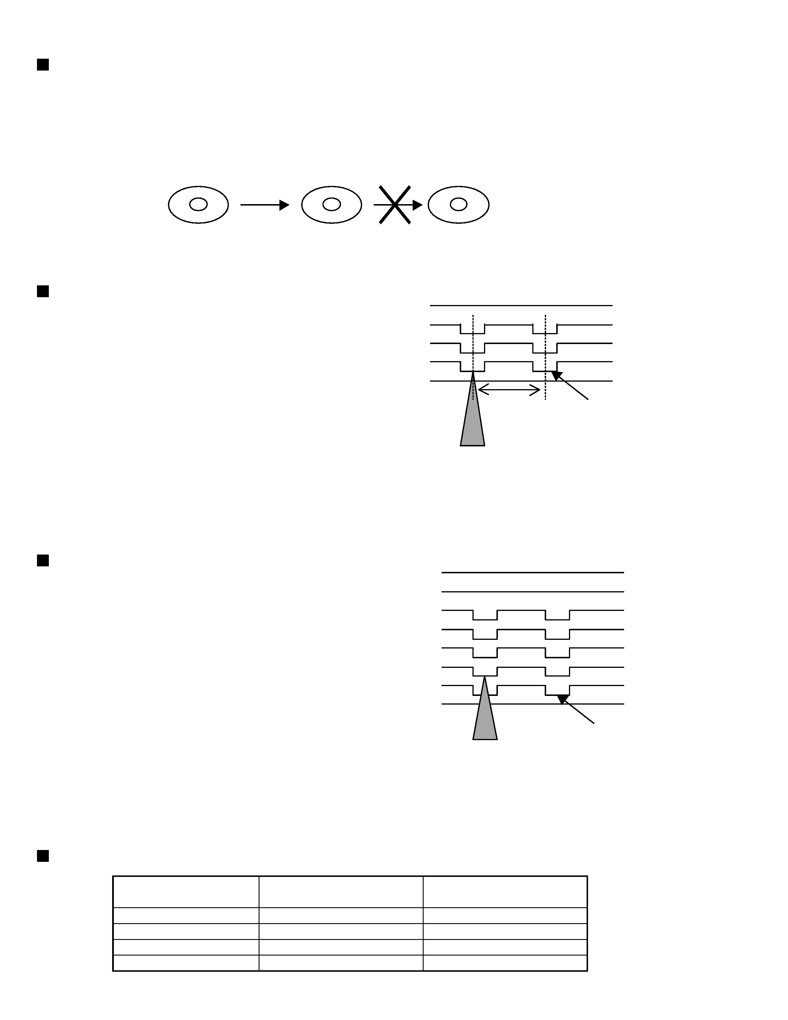
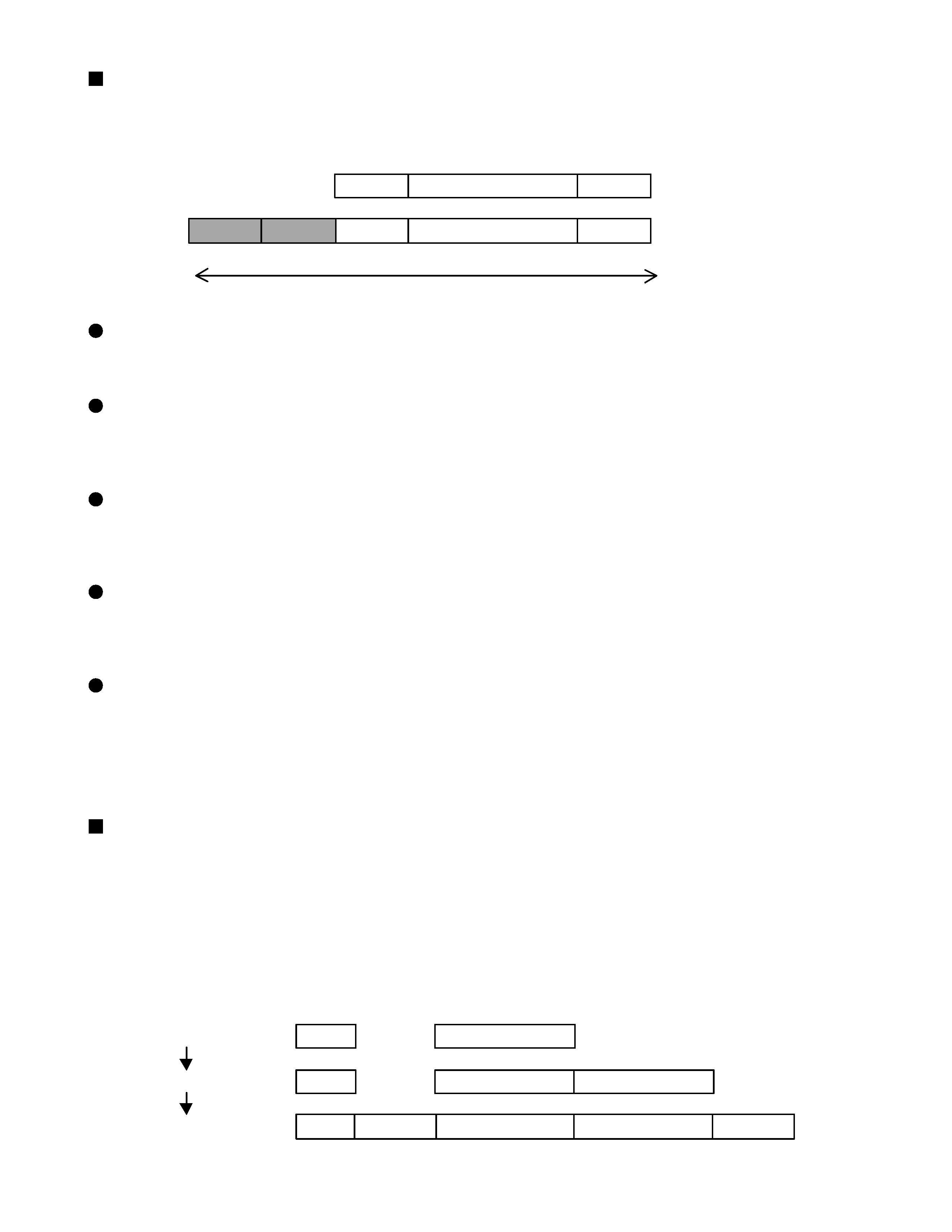
Recording method of the CD-R/RW
As shown in Fig. 6, the recording areas of a CD-ROM and a CD-R/RW are different.
These discs use two recording areas in addition to the areas used for data recording by ordinary CD discs.
Finalization
Finalization refers to writing the preliminary TOC data in the PMA into the lead-in and lead-out areas.
When a disc is not finalized, its TOC data is recorded exclusively in the PMA.
Since ordinary CD players cannot read the PCA and PMA, non-finalized discs can be read only with a
REC/PLAY machine such as the XR-D400. This makes possible addition writing on the disc.
When a disc is finalized, its lead-in, data and lead-out areas are written properly and the disc becomes a disc
complying with the Orange Book specifications.
Fig. 7 shows the finalization procedure.
2 areas for CD-ROM
Inner direction
Outer direction
PCA
PMA
Lead-in
Data
Lead-out
[Fig. 6]
[Fig. 7]
Before finalization
Track rewriting
After finalization
(Preliminary TOC)
TOC data