For Customer Use:
Enter below the Serial No. which is located on
the bottom of the body.
Retain this information for future reference.
Model No.
Serial No.
4ch Network Encoder
START-UP GUIDE
VN-E4
Thank you for purchasing this JVC product.
Before operating this unit, please read the
instructions carefully to ensure the best possible
performance.
VN-E4
LST0249-001A
/COL
STS
CH4
CH3
CH2
CH1
AUD
O.L
ALM
FDX
100M
LINK
POWER
4
4
This instruction book is made from 100% recycle paper.
© 2005 Victor Company of Japan, Limited
VN-E4
4c
h
Netw
ork
Encoder
Printed in Japan
LST0249-001A
2
These are general IMPORTANT SAFEGUARDS and certain items may not apply to all appliances.
1. Read all of these instructions.
2. Save these instructions for later use.
3. All warnings on the product and in the operating instructions should be adhered to.
4. Unplug this appliance system from the wall outlet before cleaning. Do not use liquid cleaners or aerosol cleaners.
Use a damp cloth for cleaning.
5. Do not use attachments not recommended by the appliance manufacturer as they may cause hazards.
6. Do not use this appliance near water - for example, near a bathtub, washbowl, kitchen sink, or laundry
tub, in a wet basement, or near a swimming pool, etc.
7. Do not place this appliance on an unstable cart, stand, or table. The appliance may fall, causing
serious injury to a child or adult, and serious damage to the appliance.
Use only with a cart or stand recommended by the manufacturer, or sold with the appliance.
Wall or shelf mounting should follow the manufacturer's instructions, and should use a mounting kit
approved by the manufacturer.
An appliance and cart combination should be moved with care. Quick stops, excessive force, and
uneven surfaces may cause the appliance and cart combination to overturn.
8. Slots and openings in the cabinet and the back or bottom are provided for ventilation, and to insure
reliable operation of the appliance and to protect it from overheating, these openings must not be
blocked or covered. The openings should never be blocked by placing the appliance on a bed, sofa, rug, or other similar
surface. This appliance should never be placed near or over a radiator or heat register. This appliance should not be placed
in a built-in installation such as a bookcase unless proper ventilation is provided.
9. This appliance should be operated only from the type of power source indicated on the marking label. If you are not sure of
the type of power supplied to your home, consult your dealer or local power company. For appliance designed to operate
from battery power, refer to the operating instructions.
10. For added protection for this product during a lightning storm, or when it is left unattended and unused for long periods of
time, unplug it from the wall outlet and disconnect the antenna or cable system. This will prevent damage to the product due
to lightning and power-line surges.
11. Do not allow anything to rest on the power cord. Do not locate this appliance where the cord will be abused by persons
walking on it.
12. Follow all warnings and instructions marked on the appliance.
13. Do not overload wall outlets and extension cords as this can result in fire or electric shock.
14. Never push objects of any kind into this appliance through cabinet slots as they may touch dangerous voltage points or
short out parts that could result in a fire or electric shock. Never spill liquid of any kind on the appliance.
15. Do not attempt to service this appliance yourself as opening or removing covers may expose you to dangerous voltage or
other hazards. Refer all servicing to qualified service personnel.
16. Unplug this appliance from the wall outlet and refer servicing to qualified service personnel under the following conditions:
a. When the power cord or plug is damaged or frayed.
b. If liquid has been spilled into the appliance.
c. If the appliance has been exposed to rain or water.
d. If the appliance does not operate normally by following the operating instructions. Adjust only those controls that are
covered by the operating instructions as improper adjustment of other controls may result in damage and will often require
extensive work by a qualified technician to restore the appliance to normal operation.
e. If the appliance has been dropped or the cabinet has been damaged.
f. When the appliance exhibits a distinct change in performance - this indicates a need for service.
17. When replacement parts are required, be sure the service technician has used replacement parts specified by the
manufacturer that have the same characteristics as the original part. Unauthorized substitutions may result in fire, electric
shock, or other hazards.
18. Upon completion of any service or repairs to this appliance, ask the service technician to perform routine safety checks to
determine that the appliance is in safe operating condition.
SAFETY PRECAUTIONS (For USA)
The lightning flash wish arrowhead symbol, within
an equilateral triangle is intended to alert the user to
the presence of uninsulated "dangerous voltage"
within the product's enclosure that may be of
sufficient magnitude to constitute a risk of electric
shock to persons.
The exclamation point within an equilateral triangle
is intended to alert the user to the presence of
important operating and maintenance (servicing)
instructions in the literature accompanying the
appliance.
NOTE:
This equipment has been tested and found to comply with the limits
for a Class A digital device, pursuant to Part 15 of the FCC Rules.
These limits are designed to provide reasonable protection
against harmful interference when the equipment is operated in a
commercial environment.
This equipment generates, uses, and can radiate radio frequency
energy and, if not installed and used in accordance with the
instruction manual, may cause harmful interference to radio
communications.
Operation of this equipment in a residential area is likely to cause
harmful interference in which case the user will be required to
correct the interference at his own expense.
CAUTION
Changes or modifications not approved by JVC could void user's
authority to operate the equipment.
IMPORTANT SAFEGUARDS
S3125A
NOTE:
The rating plate (serial number plate) is on the bottom.
WARNING:
TO REDUCE THE RISK OF FIRE OR ELECTRIC SHOCK, DO NOT
EXPOSE THIS APPLIANCE TO RAIN OR MOISTURE.
CAUTION:
This unit should be used with attached AC Adaptor.
To prevent electric shocks and fire hazards, do NOT use any
other power source.
3
SAFETY PRECAUTIONS (For Europe)
Caution for AC Mains Lead
FOR YOUR SAFETY PLEASE READ THE FOLLOWING TEXT CAREFULLY.
This product is equipped with 2 types of AC cable. One is for continental Europe, etc. and the other one is only for U.K.
Appropriate mains cable must be used in each local area, since the other type of mains cable is not suitable.
Information for Users on Disposal of Old Equipment
[European Union]
This symbol indicates that the electrical and electronic equipment should not be disposed as general household waste at its
end-of-life. Instead, the product should be handed over to the applicable collection point for the recycling of electrical and
electronic equipment for proper treatment, recovery and recycling in accordance with your national legislation.
By disposing of this product correctly, you will help to conserve natural resources and will help prevent potential negative
effects on the environment and human health which could otherwise be caused by inappropriate waste handling of this
product. For more information about collection point and recycling of this product, please contact your local municipal office,
your household waste disposal service or the shop where you purchased the product.
Penalties may be applicable for incorrect disposal of this waste, in accordance with national legislation.
(Business users)
If you wish to dispose of this product, please visit our web page www.jvc-europe.com to obtain information about the take-
back of the product.
[Other Countries outside the European Union]
If you wish to dispose of this product, please do so in accordance with applicable national legislation or other rules in your
country for the treatment of old electrical and electronic equipment.
IMPORTANT:
Connection to the mains supply in the United Kingdom.
DO NOT cut off the mains plug from this equipment.
If the plug fitted is not suitable for the power points in your home or
the cable is too short to reach a power point, then obtain a proper
safety approved extension lead/adapter or consult your dealer.
In the unlikely event of the plug fuse failing be sure to replace
the fuse only with an identical approved type, as originally fit-
ted, and to replace the fuse cover. If the fuse fails again consult
your nearest JVC dealer.
If nonetheless the mains plug is cut off remove the fuse and dispose
of the plug immediately, to avoid a possible shock hazard by
inadvertent connection to the mains supply.
If this product is not supplied fitted with a mains plug then follow the
instructions given below:
DO NOT make any connection to the Larger Terminal coded E or
Green.
The wires in the mains lead are coloured in accordance with the
following code:
If these colours do not correspond with the terminal identifications of
your plug, connect as follows:
Blue wire to terminal coded N (Neutral) or coloured Black.
Brown wire to terminal coded L (Live) or coloured Red.
If in doubt -- consult a competent electrician.
Blue to N (Neutral) or Black
Brown to L (Live) or Red
WARNING:
TO REDUCE THE RISK OF FIRE OR ELECTRIC SHOCK, DO
NOT EXPOSE THIS APPLIANCE TO RAIN OR MOISTURE.
CAUTION
To prevent electric shock, do not open the cabinet. No user service-
able parts inside. Refer servicing to qualified service personnel.
WARNING
This is a Class A product. In a domestic environment this product
may cause radio interference in which case the user may be required
to take adequate measure.
FOR CONTINENTAL EUROPE, ETC.
FOR U.K. ONLY
Not to be used in the U.K.
If the plug supplied is not suitable for your socket outlet, please use
appropriate one.
ATTENTION:
This symbol is
only valid in the
European Union.
4
Introduction
Features
Thank you for purchasing this JVC product. Before operating
this unit, please read these instructions carefully to ensure the
best possible performance.
These instructions are for VN-E4U and VN-E4E.
Distribution of 4-channel images to the network
VN-E4 compresses 4-channel video input images in the
JPEG format. Each channel may be distributed at a
maximum rate of 30 fps by TCP or Multicast. The
maximum rate for 4 channels is 120 fps in total. Either
VGA or QVGA may be selected as the frame size. It is
also possible to simultaneously distribute a video input in
both types of frame sizes.
Audio distribution to the network
VN-E4 compresses 1-channel audio input in the µ-law
format. Audio is distributed by TCP or Multicast. VN-E4
comes with a built-in echo canceller. Use this during bi-
directional audio transmission.
Reception and output of audio signals from the network
VN-E4 enables output of µ-law received from the network
as audio signals.
Built-in Viewer
VN-E4 comes with a built-in ActiveX viewer. Monitoring of
VN-E4 images and audio using the PC is possible by
installing this built-in viewer on the PC.
Motion detect and alarm input
VN-E4 is equipped with motion detect function that can
detect motion in each video input. It also comes with a 4-
channel alarm input. It is possible to invoke actions such
as notification to clients, alarm output, sending of mails
and JPEG file transfer by detection of motion or alarm
input.
Controlling external devices connected to the serial port
VN-E4 comes with 2 serial ports. It is possible to control
external devices connected to the serial ports from the
clients.
Restrictions on Clients
VN-E4 can permit or deny access from clients based on
registered IP addresses.
Refer to
AINSTRUCTIONSB manual and AAPI GUIDEB in CD-ROM for advanced information.
CONTENT
IMPORTANT SAFEGUARDS ......................................................2
SAFETY PRECAUTIONS ............................................................3
Introduction ................................................................................4
Features .................................................................................4
Cautionary Notes ..................................................................5
How to view this manual ......................................................5
Name and Function of Parts ................................................6
Preparation .................................................................................8
System Connection Example ..................................................8
Connection / Installation .........................................................9
AC Adaptor ............................................................................9
Network .................................................................................9
Connection with PC ..............................................................9
AV Devices ............................................................................9
Attaching Rack Mount Brackets .......................................10
IP Address Setting ...................................................................11
(A) Assigning IP Address from the DHCP Server................11
(B) Assigning a Static IP Address.........................................11
(1) System configuration for setting the IP address .......11
(2) IP address setting on PC ..............................................12
(3) Changing IP Address Using Internet Explorer ...........13
Basic Operation (Viewing) .......................................................16
Image Display Using Internet Explorer.................................16
Viewing Using Built-in Viewer ...............................................17
(1) Setting up Internet Explorer .........................................17
(2) Installing the built-in viewer .........................................19
(3) Operating the viewer .....................................................20
(4) Exiting the viewer.......................................................... 21
(5) Viewer shortcut ............................................................. 22
Others ........................................................................................23
Specifications .........................................................................23
5
Cautionary Notes
Storage/usage location
Do not use or store the unit in the following locations.
Malfunction may occur as a result.
Location outside the allowed operating temperature range
(0 I to 40 I) where the temperature may become
extremely hot or cold.
Location outside the allowed operating humidity range
(20 % to 80 %) where the humidity is high.
Location with strong magnetic force such as from a
transformer, motor, etc.
Location with presence of electric waves such as from a
transceiver, mobile phone, etc.
Location that is dusty or sandy.
Location with strong vibrations.
Location with condensation.
Location where radiation, x-ray or corrosive gas is
generated.
Handling
To prevent the internal temperature from rising, do not stack
units when using.
Do not place the unit on its side.
Handle the unit with caution and do not apply excessive
force.
Wipe the unit with a soft cloth.
The surface may fog or even melt when wiped with benzene
or paint thinner. For stubborn dirt, use neutral detergent
diluted in water and then dry wipe.
To completely cut off the power, disconnect the power cable
from the wall outlet or remove the power cord from the AC
adaptor.
Installation
Be sure to ground the unit.
Place the unit near a wall outlet.
Always use the specified (included) power cord and AC
adaptor.
Use of a cord other than that specified or a cord that has
been damaged may result in fire or electrical shock.
Do not use power cord or AC adaptor other than with this
unit.
Do not place heavy objects such as a monitoring television
on top of the unit. Malfunction may occur as a result.
About the echo canceller
The echo canceller of the unit is provided for the prevention
of howling. However, repeated echoing of sound other than
from a VN-E4 may not be suppressed sufficiently.
When using a speaker and a microphone at the same time,
place them apart, change the direction of the microphone or
take caution so that the playback sound from the speaker is
not picked up by the microphone.
When using a camcorder with audio AGC (Auto Gain
Control), the echo canceller may not work properly. Please
turn off the AGC.
If the AGC feature cannot be turned off, use a separate
microphone amplifier with no AGC.
When not using the unit for a long time, turn the power of
the unit off for conserving energy.
About electrical interference
When using the unit near a television, radio receiver or
transceiver, screen images may become disturbed or noise
may be heard. In this case, try the following:
Place the unit away from radios and televisions or change
the direction of the unit.
If an indoor antenna is used, change the direction or the
location of the antenna.
Use a wall outlet other than the one used for radios,
televisions, etc.
Install a commercially-available noise filter between the
wall output and power plug.
How to view this manual
Symbols used
NOTE
: Items concerning the operations of this
product are described.
MEMO
: References concerning the usage,
restrictions, etc. of this product are described.
A
:Reference pages and reference items are
indicated.
About the contents of this manual
All rights reserved by JVC. Unauthorized duplication or
reprinting of this manual, in whole or in part, is strictly
prohibited.
Windows is a registered trademark of Microsoft
Corporation in the U.S.
All other product names used in this manual are
trademarks or registered trademarks of their respective
companies. Please note that marks such as
, , , etc.
have been omitted in this manual.
Illustrated designs, specifications and other contents of
this manual are subject to change without prior notice.
JVC assumes no responsibility whatsoever of any effects
that may occur as a result of operating this unit.
6
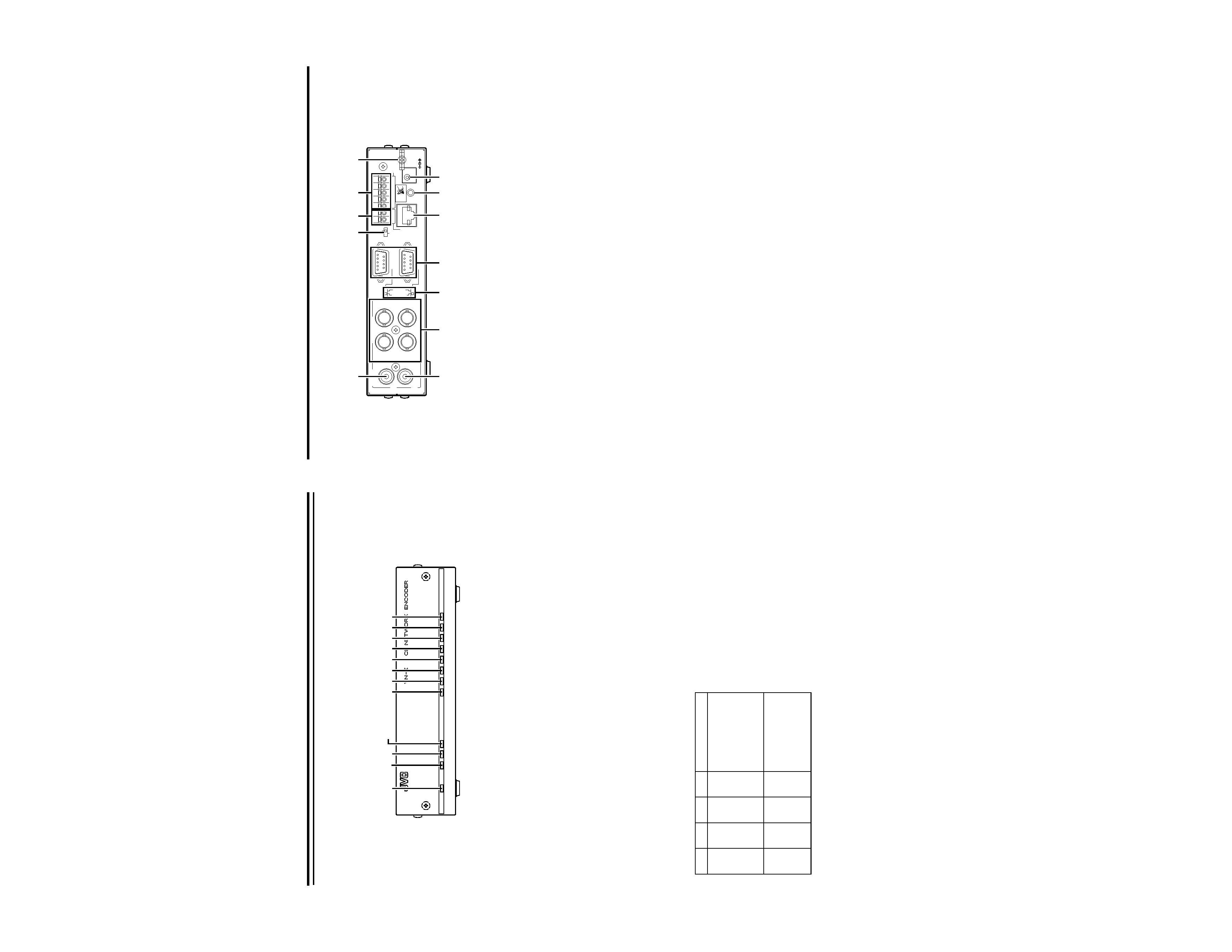
Name and Function of Parts
[Front]
A [POWER] Lamp
Lights up when the power of VN-E4 is turned on.
B [LINK] Lamp
Lights up when VN-E4 is connected to the network.
C [100M] Lamp
Lights up when VN-E4 is connected to the network via
100Base. The light will not be illuminated in the case of
10Base.
D [FDX/COL] Lamp
Lights up when VN-E4 is connected to the network via full
duplex. The light will not be illuminated in the case of half
duplex. The light will appear blinking when collision occurs.
E [STS] Status Lamp
Lights up when VN-E4 is started up properly. The light will
appear blinking when troubles occur during startup and the
error details will be displayed in CH1-CH4.
F [ALM] Alarm Lamp
Displays alarm input to VN-E4. Lights up when there are
changes in the alarm input or when motion is detected. The
light will turn off automatically after 5 seconds.
G [O.L] Overload Lamp
Displays the processing load of VN-E4. This light is turned
off when this unit is functioning properly. This light is turned
on when the processing load of VN-E4 is too heavy.
H [AUD] Audio Lamp
Displays the audio transmission status of VN-E4. Lights up
during transmission of audio data to the network. Turns off
when there is no transmission.
I [CH1] Video 1 Channel Lamp
Displays the image transmission status of VN-E4. Lights up
during transmission of video input at Ch1 to the network.
Turns off when there is no transmission.
J [CH2] Video 2 Channel Lamp
Displays the image transmission status of VN-E4. Lights up
during transmission of video input at Ch2 to the network.
Turns off when there is no transmission.
K [CH3] Video 3 Channel Lamp
Displays the image transmission status of VN-E4. Lights up
during transmission of video input at Ch3 to the network.
Turns off when there is no transmission.
L [CH4] Video 4 Channel Lamp
Displays the image transmission status of VN-E4. Lights up
during transmission of video input at Ch4 to the network.
Turns off when there is no transmission.
/COL
STS
CH4
CH3
CH2
CH1
AUD
O.L
ALM
FDX
100M
LINK
POWER
4
4
A
B C DE F GH I J K L
CH1
CH2
CH3
CH4
Error Description
Light
OFF
Light
OFF
Light
OFF
Light
ON
A device with the same
IP address as VN-E4 is
detected. The lamps
will not change until
the power of VN-E4 is
turned off.
Light
OFF
Light
OFF
Light
ON
Light
OFF
There is no video
signal input to VN-E4.
The normal display will
be restored upon input
of video signals.
7
[Back]
M [AUDIO IN] terminal (RCA pin)
For input of audio signals.
N [AUDIO OUT] terminal (RCA pin)
For output of audio signals.
O [VIDEO INPUT 1CH to 4CH] terminal (BNC)
For input of video signals.
P [RS-232C/RS-485] COM1, 2 Protocol Selection Switch
For switching between RS-232C and RS-485 of COM 1
and COM 2.
Q [COM1, COM2] terminal (D-sub 9P)
Serial port for controlling external devices.
R [CONTROL/SERVICE] switch
Switch for switching COM1 to servicing. Select CONTROL
for normal use. Select SERVICE during maintenance.
S [ALARM OUTPUT] terminal
The COM and OUT terminals form the make contact.
Alarm output changes to break upon turning off the power
of VN-E4, and alarm output is restored to the previous
state upon turning on the power again.
T [ALARM INPUT] terminal
Input terminal for no-voltage make contact or break
contact. This consists of 4 input and 1 ground terminals.
U [10 BASE-T/100 BASE-TX] LAN terminal
For connecting the network cable.
V [RESET] button
Button for resetting VN-E4. Power will be reset upon
pressing this button and releasing it within 5 seconds.
If this button is pressed for 5 seconds or longer, LEDs from
STS to CH4 will start to blink and all settings will be
restored to their factory defaults.
W Wire Clamp
For securing the cable of the AC adaptor.
X [DC 5V] Power Terminal
For connecting the AC adaptor supplied.
VN-E4 does not come with a power switch. It starts up
automatically upon supply of power using the AC adaptor.
PUSH
ALARM
AUDIO
VIDEO INPUT
IN
OUT
SERVICE
CONTROL
RS-485
RS-232C
INPUT
OUTPUT
COM2
10BASE-T/100BASE-TX
2CH
4CH
3CH
1CH
COM OUT
12
3 4
G
DC 5V
RESET
COM1
M
R S
TW
U
V X
N
O
PQ
8
Preparation
This manual aims at familiarizing users with the fundamental uses of VN-E4 by providing explanations on the monitoring system
using the built-in viewer in LAN.
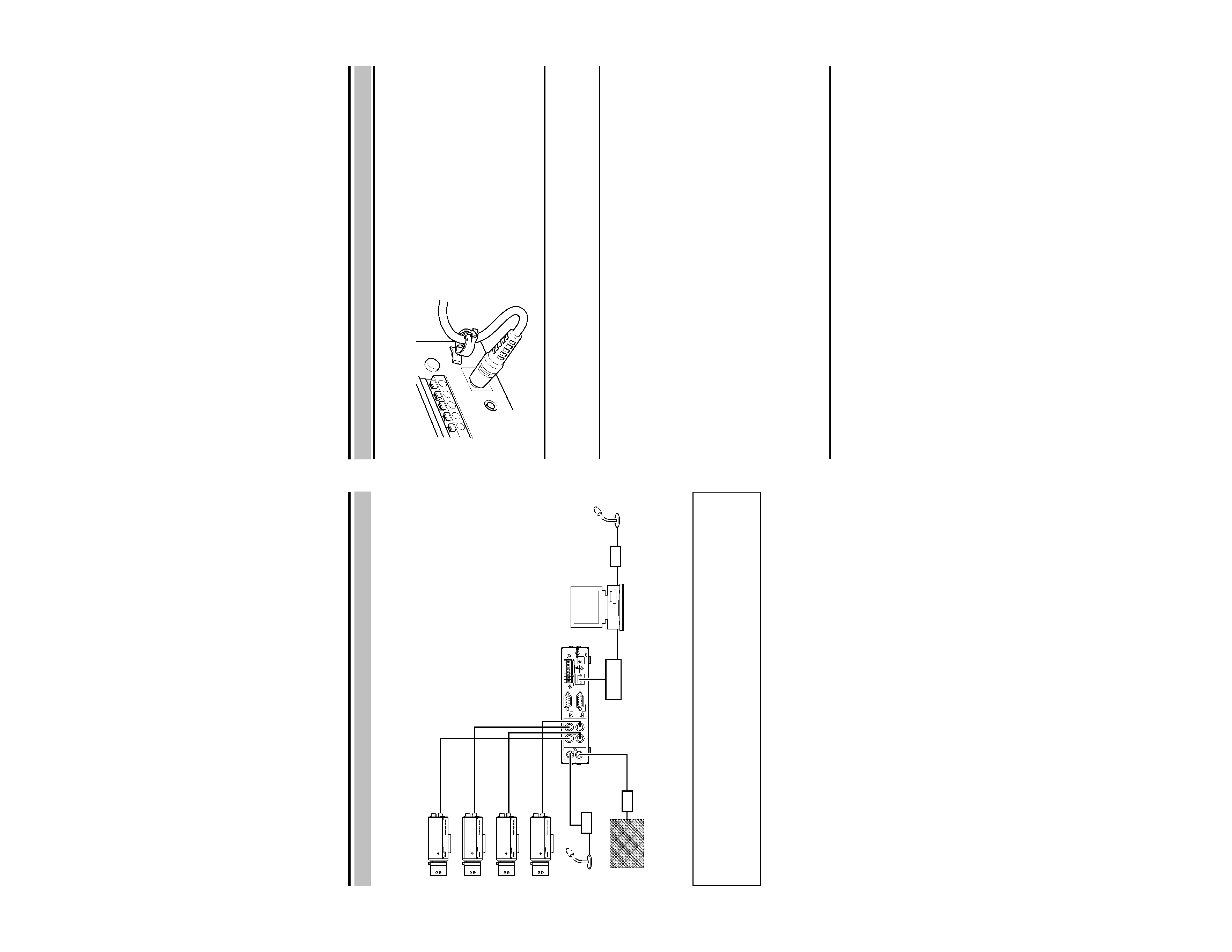
System Connection Example
PUSH
ALARM
AUDIO
VIDEO INPUT
IN
OUT
SERVICE
CONTROL
RS-485
RS-232C
INPUT
OUTPUT
COM2
10BASE-T/100BASE-TX
2CH
4CH
3CH
1CH
COM OUT
12
3 4
G
DC 5V
RESET
COM1
ALC
LEVEL
Av
Pk
LH
ALC
LEVEL
Av
Pk
LH
ALC
LEVEL
Av
Pk
LH
ALC
LEVEL
Av
Pk
LH
VIDEO IN 1
VIDEO IN 2
VIDEO IN 3
VIDEO IN 4
AUDIO OUT
AUDIO IN
SW HUB
PC
Camera 1
Camera 2
Camera 3
Camera 4
Microphone
Amplifier
Speaker
Amplifier
Microphone
Amplifier
NOTE
The following operations are possible using this system.
Monitoring of images on Camera 1 - 4 via the PC display
One-shot recording of the current image on the PC's hard disk
Audio transmission from VN-E4 to PC and output from the PC's sound card
Audio transmission from PC to VN-E4 and output from VN-E4
For more details on the use of VN-E4, please refer to
AINSTRUCTIONSB manual.
9
AC Adaptor
Connect the AC adaptor cable to the power terminal of VN-E4, followed by securing the cable using the wire clamp. Plug the
power cable into the AC adaptor, followed by the power cable plug to the power source.
Network
Connect VN-E4 to the switching hub using a straight LAN cable of Category 5 or above.
The system in the examples of this manual does not make use of serial ports and alarm input. For details on their uses, please
refer to
AINSTRUCTIONSB manual.
Connection with PC
Connect the PC to the switching hub using a straight LAN cable.
The system in the examples of this manual makes use of Internet Explorer or the built-in viewer of VN-E4 for viewing.
[Recommended PC Specifications for Viewing]
OS
: WindowsXP Pro (SP2) or Home (SP2)
CPU
: 1.5 GHz for viewing of 1 channel (30 fps)
3.4 GHz for viewing of 4 channels (120 fps)
Memory
: 1 GB
Hard disk
: Free disk space of 20 MB and above
Video card
: 1024 x 768 pixels or higher, True Color (24 or 32 bits)
Sound card
: Sound Blaster (PCI recommended)
Web browser
: Internet Explorer V6.0
To play back at 30 fps using the built-in viewer, CPU over 1.5 GHz is recommended. To play back at 120 fps, CPU over 3.4
GHz is recommended.
[IP Address Setting]
Set the IP address of the PC to enable communication with VN-E4. Please refer to
A(2) IP address setting on PCB on
procedures to alter the IP address.
[AV Devices]
Connect a microphone to the audio input of the PC via the amplifier.
When speakers other than the PC's built-in speaker is used, connect the speaker to the audio output of the PC via the amplifier.
AV Devices
Connect up to 4 cameras to the 4 video input terminals at the rear panel of VN-E4. Output signals of each camera need not be
synchronized.
Connect a microphone to the audio input terminal at the rear panel of VN-E4 via the amplifier.
Connect a speaker to the audio output terminal at the rear panel of VN-E4 via the amplifier.
Connection / Installation