INSTRUCTIONS
FIXED DOME NETWORK CAMERA
VN-C205
LWT0280-001A
For Customer Use:
Enter below the Serial No. which is
located on the body. Retain this
information for future reference.
Model No.
VN-C205
Serial No.
LWT0280-001A
© 2005 Victor Company of Japan, Limited.
VN-C205
FIXED
DOME
NETWORK
CAMERA
2
Safety Precautions
CAUTION:TO REDUCE THE RISK OF ELECTRIC
SHOCK. DO NOT REMOVE COVER (OR
BACK). NO USER-SERVICEABLE PARTS
INSIDE.REFER
SERVICING
TO
QUALIFIED SERVICE PERSONNEL.
The lightning flash wish arrowhead
symbol, within an equilateral triangle is
intended to alert the user to the pres-
ence of uninsulated "dangerous volt-
age" within the product's enclosure that
may be of sufficient magnitude to con-
stitute a risk of electric shock to per-
sons.
The exclamation point within an equi-
lateral triangle is intended to alert the
user to the presence of important op-
erating and maintenance (servicing)
instructions in the literature accompa-
nying the appliance.
WARNING:
TO REDUCE THE RISK OF FIRE OR
ELECTRIC
SHOCK, DO
NOT
EXPOSETHIS APPLIANCETO RAIN
OR MOISTURE.
RISK OF ELECTRIC SHOCK
DO NOT OPEN
CAUTION
INFORMATION (FOR CANADA)
RENSEIGNEMENT (POUR CANADA)
This Class A digital apparatus complies with
Canadian ICES-003.
Cet appareil numérique de la Class A est
conforme á la norme NMB-003 du Canada.
AVERTISSEMENT:
POUR EVITER LES RISQUES
D'INCENDIE OU D'ELECTRO-
CUTION,
NE
PAS
EXPOSER
L'APPAREIL A L'HUMIDITE OU A LA
PLUIE.
Due to design modifications, data given in this
instruction book are subject to possible change
without prior notice.
FOR USA AND CANADA
Information for USA
This device complies with part 15 of the FCC Rules.
Changes or modifications not approved by JVC could
void the user's authority to operate the equipment.
This equipment has been tested and found to comply
with the limits for a Class A digital device, pursuant
to Part 15 of the FCC Rules. These limits are
designed to provide reasonable protection against
harmful interference when the equipment is operated
in a commercial environment. This equipment
generates, uses, and can radiate radio frequency
energy and, if not installed and used in accordance
with the instruction manual, may cause harmful
interference to radio communications. Operation of
this equipment in a residential area is likely to cause
harmful interference in which case the user will be
required to correct the interference at his own
expense.
This device complies with Part 15 of the FCC Rules.
Operation is subject to the following two conditions:
(1) This device may not cause harmful interference,
and (2) this device must accept any interference
received, including interference that may cause
undesired operation.
WARNING (FOR EUROPE):
This is a Class A product. In a domestic environment
this product may cause radio interference in which
case the user may be required to take adequate
measures.
This installation should be made by a qualified
service person and should conform to all local
codes.
This installation shall be in accordance with the
National Electrical Code, ANSI/NFPA 70.
The unit is to be powered by a DC 12 V or an
AC 24 V power supply.
The AC 24 V power supply should conform to
the following : Class 2 only (For USA), Isolated
power supply only (For Europe).
Any Mention in this manual of Alarm inputs/
outputs have not been evaluated by UL to be
used for Burglar Alarm Functionality.
3
PORTABLE CART WARNING
(symbol provided by RETAC)
S3125A
IMPORTANT SAFEGUARDS
1.
Read all of these instructions.
2.
Save these instructions for later use.
3.
All warnings on the product and in the operating instructions should be adhered to.
4.
Unplug this appliance system from the wall outlet before cleaning. Do not use liquid cleaners or aerosol
cleaners. Use a damp cloth for cleaning.
5.
Do not use attachments not recommended by the appliance manufacturer as they may cause hazards.
6.
Do not use this appliance near water - for example, near a bathtub, washbowl, kitchen sink, or laundry tub, in
a wet basement, or near a swimming pool, etc.
7.
Do not place this appliance on an unstable cart, stand, or table. The appliance may
fall, causing serious injury to a child or adult, and serious damage to the appliance.
Use only with a cart or stand recommended by the manufacturer, or sold with the
appliance. Wall or shelf mounting should follow the manufacturer's instructions, and
should use a mounting kit approved by the manufacturer. An appliance and cart
combination should be moved with care.
Quick stops, excessive force, and uneven surfaces may cause the appliance and
cart combination to overturn.
8.
Slots and openings in the cabinet and the back or bottom are pro-vided for ventila-
tion, and to insure reliable operation of the appliance and to protect it from over-
heating, these openings must not be blocked or covered.The openings should never
be blocked by placing the appliance on a bed, sofa, rug, or other similar surface.
This appliance should never be placed near or over a radiator or heat register. This appliance should not be
placed in a built-in installation such as a bookcase unless proper ventilation is provided.
9.
This appliance should be operated only from the type of power source indicated on the marking label. If you
are not sure of the type of power supplied to your home, consult your dealer or local power company. For
appliance designed to operate from battery power, refer to the operating instructions.
10. This appliance system is equipped with a 3-wire grounding type plug (a plug having a third (grounding) pin).
This plug will only fit into a grounding-type power outlet. This is a safety feature. If you are unable to insert the
plug into the outlet, contact your electrician to replace your obsolete outlet. Do not defeat the safety purpose
of the grounding plug.
11. For added protection for this product during a lightning storm, or when it is left unattended and unused for
long periods of time, unplug it form the wall outlet and disconnect the antenna or cable system. This will
prevent damage to the product due to lightning and power-line surges.
12. Do not allow anything to rest on the power cord. Do not locate this appliance where the cord will be abused by
persons walking on it.
13. Follow all warnings and instructions marked on the appliance.
14. Do not overload wall outlets and extension cords as this can result in fire or electric shock.
15. Never push objects of any kind into this appliance through cabinet slots as they may touch dangerous voltage
points or short out parts that could result in a fire or electric shock. Never spill liquid of any kind on the
appliance.
16. Do not attempt to service this appliance yourself as opening or removing covers may expose you to danger-
ous voltage or other hazards. Refer all servicing to qualified service personnel.
17. Unplug this appliance from the wall outlet and refer servicing to qualified service personnel under the follow-
ing conditions:
a. When the power cord or plug is damaged or frayed.
b. If liquid has been spilled into the appliance.
c. If the appliance has been exposed to rain or water.
d. If the appliance does not operate normally by following the operating instructions. Adjust only those con-
trols that are covered by the operating instructions as improper adjustment of other controls may result in
damage and will often require extensive work by a qualified technician to restore the appliance to normal
operation.
e. If the appliance has been dropped or the cabinet has been damaged.
f.
When the appliance exhibits a distinct change in performance - this indicates a need for service.
18. When replacement parts are required, be sure the service technician has used replacement parts specified
by the manufacturer that have the same characteristics as the original part. Unauthorized substitutions may
result in fire, electric shock, or other hazards.
19. Upon completion of any service or repairs to this appliance, ask the service technician to perform routine
safety checks to determine that the appliance is in safe operating condition.
These are general IMPORTANT SAFEGUARDS and certain items may
not apply to all appliances.
4
Contents ................................................................................................. 4
Characteristics ....................................................................................... 6
Operating Precautions ........................................................................... 6
Operating Environment .......................................................................... 8
Latest Updates ....................................................................................... 8
Name and Function of Parts .................................................................. 9
Connection Examples .......................................................................... 12
Preparation Procedure ......................................................................... 13
Step 1 Connection/Installation
1-1 The flowchart of installation work for camera ............................. 14
1-2 Mounting the Camera to the Ceiling .......................................... 16
1. Preparations ............................................................................. 16
Connection to Alarm Input/Output Terminal ............................. 18
Inserting the CF card ............................................................... 19
2. Installation ................................................................................ 20
Connection of the Input Power Cable ....................................... 22
3. Adjustment of the camera's angle of view ................................ 23
1-3 When installing the Camera to the electrical box ......................... 25
1-4 Pull out the cables aside and mount ............................................ 26
1-5 White-spot correction ................................................................... 26
Step 2 Network Settings
2-1 Installing the Software ................................................................ 27
2-2 Setting PC's IP Address [Windows XP] ..................................... 28
Setting PC's IP Address [Windows 2000] .................................. 30
2-3 Setting IP Address for this Camera Using the "VN-C205U Setup Tool" .. 32
2-4 Other Settings Using the "VN-C205U Setup Tool" ..................... 34
1. Password Setting ..................................................................... 35
2. Multicast ................................................................................... 36
3. Motion Detection Setting .......................................................... 38
4. Alarm Setting ........................................................................... 40
5. Recording Setting .................................................................... 45
6. Web .......................................................................................... 48
7. FTP Server ............................................................................... 49
Introduction
Contents
Preparation
Settings
(VN-C205U Setup
Tool)
Introduction
Thank you for purchasing this product.
(These instructions are for VN-C205U.)
Before beginning to operate this unit, please read the instruction manual carefully in
order to make sure that the best possible performance is obtained.
5
8. FTP Client Setting .................................................................... 50
9. Time Setting ............................................................................. 52
10. Memory Information ................................................................. 53
2-5 Registering Connected Camera Using the "V.Networks Controller" . 54
Step 3 Setting Using the V.Networks Controller
3-1 Starting Up the V.Networks Controller ....................................... 56
3-2 Features that Allow Setting Using the V.Networks Controller .... 57
3-3 Motion Detection Standby .......................................................... 58
3-4 Image Size and Inversion .......................................................... 59
3-5 Image Quality Setting ................................................................ 60
3-6 Frame Rate ................................................................................ 61
3-7 Alarm Setting ............................................................................. 62
3-8 Time Stamp ............................................................................... 64
3-9 Changing Registered Information .............................................. 65
Step 4 Operating Using the V.Networks Controller
4-1 Features that Allow Operation Using the V.Networks Controller .. 66
4-2 Record/Stop ............................................................................... 67
4-3 Playback .................................................................................... 68
4-4 Cautions on Record/Play Functions ........................................... 70
4-5 Snapshot .................................................................................... 71
Step 5 Operating Using a Web Browser
5-1 Operating Environment .............................................................. 72
5-2 Access Authorization Level ........................................................ 73
5-3 Starting Up the Web Browser .................................................... 74
5-4 Setting Using the Web Browser ................................................. 75
1. Other Settings .......................................................................... 76
2. View Setting ............................................................................. 79
3. Alarm Setting ........................................................................... 80
4. FTP Setting .............................................................................. 82
5-5 Viewing Still Images ................................................................... 84
5-6 Viewing Live Images .................................................................. 85
5-7 Image Link ................................................................................. 86
Troubleshooting .................................................................................... 87
Specifications ....................................................................................... 89
Operation
(V.Networks
Controller)
Operation
(Web Browser)
Others
Settings
(V.Networks
Controller)
Settings
(VN-C205U Setup
Tool)
6
Characteristics
The camera uses a high-resolution
380,000 pixel, high-Senstivity CCD to realize
high picture quality with horizontal resolution
of 540 TV lines.
Frame Rate
Supports a maximum frame rate of 30 fps
when resolution is 640 x 480 in the JPEG
compression format.
Supports Multicast
Support for multicast enables sending of an
image data to multiple PCs on the network
at one time without lowering the frame rate.
Built-in CF (Compact Flash) Slot
Interface with alarms and enables storage of
a recording file in the CF card. Please
purchase the CF card separately.
Motion Detection Feature
Enables output of alarm upon detecting
motion of images within a specified area.
Built-in Web Server
Enables browsing using the Internet Explorer.
Operating Precautions
To save energy, turn off the power supply of
the system when not in use.
This camera is intended for indoor use. It
cannot be used outdoors.
Do not install or use the camera in the
following locations.
· Places exposed to rain or water
· Places containing vapor or oil soot, such
as kitchens
· Places exceeding the operating ambient
temperature range (0° to 40°)
·Places where corrosive gases are
generated
· Places nearby radiation or X-rays as well
as sources of strong radio waves or
magnetism
· Places subject to vibration
· Places with excessive dust
Insufficient ventilation may cause the camera
to malfunction. Be careful not to block
ventilation around the camera.
This camera radiates heat from its surfaces
(top panel facing ceiling and side panel). Do
not install at a location that may trap heat,
such as near the walls.
Do not install at a location that may expose the
camera directly to cool air, such as nearby the
air outlet of air conditioners. This may cause
moisture to condense within the dome cover.
Dew condensation may occur when there is
a drastic change in the ambient temperature
of the camera, hence causing a malfunction.
When the camera is installed at such
locations, turn on the power after allowing it
to dry for a few hours.
Do not point the camera lens at a strong light
source such as the sun. Doing so may cause
the camera to malfunction.
This camera contains a built-in AGC circuit.
As a result, gain increases at dark places
and screen may appear grainy. This is not a
malfunction.
When an equipment that generates a strong
magnetic field, such as transceivers, is used
near this camera with the AGC turned on, beat
noises may appear in the image. When using
a transceiver, therefore, place it at least 3 m
away from this camera.
If this camera or cable connected this unit is
used near a location where strong electrical
or magnetic waves are generated (eg. radios,
TVs, transformers, monitors, etc.), noise
interference may occur in the image or its
color may be affected.
When this camera is used in the White Balance
(ATW) mode, the colors captured may differ
slightly from the actual colors due to the
operational principles of the auto-tracking
white balance circuit. This is not a malfunction.
Introduction
7
When shooting a bright object (eg. lamps,
etc.), white vertical streaks may appear on
the object on the screen. This is a
phenomenon (smear phenomenon) normal
to CCDs (solid-state image pickup devices)
and is not a malfunction.
The dome cover is hemispherical in shape, and
therefore images tend to be distorted at the
edges of the hemisphere. The edges of the
hemisphere is masked for this camera. When
the camera is tilted and pointed in the horizontal
direction, therefore, edges of the hemisphere
may enter the angle of view, hence causing
the upper end of the screen to appear dark
and the image to go out of focus.
When shooting an object that is near a light
source (eg. lightings) or with a large
difference in brightness, ghosting may occur
on the screen. This phenomenon is due to
the characteristics of the dome cover and
built-in lens and is not a malfunction.
Ensure to use the Converter Unit that has
been supplied.
Certain Hubs/switches that are equipped with
the SNMP feature may come with a broadcast
or multicast control function. Proper viewing
of multicast images created by this camera
may not be possible if this function is enabled.
Do not touch the dome cover with your hand.
This may dirty the cover and cause the image
quality to deteriorate.
To clean the camera.
· Do so upon turning off the power.
· Use a lens cloth (or paper) to remove dirt
from the dome cover. The camera may
acquire dirt over a short period of time,
depending on the environment of use.
When there is excessive dirt, wipe using a
lens cloth (or paper) upon wetting it in a
neutral detergent diluted with water.
If the D/N switch is turned on, the mode
changes automatically to black and white in
dark places. As the sensitivity increases, the
image may look grainy and white spots may
appear. When changing modes, bright
portions of image may be emphasized but
this is not a failure of the camera.
The unit is to be powered by a DC 12 V or an
AC 24 V power supply.
The AC 24 V power supply should conform to
the following : Class 2 only (For USA), Isolated
power supply only (For Europe).
The rating label is displayed on the underside
of the body.
Install at places that are strong enough
to support the camera weight.
Install this camera at places that are strong
enough to support its weight upon taking
into consideration the vibration force during
high-speed rotation as well as its mass
(approx. 1.0 kg). For ceiling materials that
are weak, such as overlay plywood and
plaster boards, reinforce by applying
reinforcements (veneer plywood). If
reinforcement is inadequate, image on the
monitor screen may be blurred due to
vibrations. In the worst scenario, it may even
fall and cause serious injuries if there is
someone underneath.
Warning
JVC will not be liable for any damage resulting
from the camera dropping due to incomplete
installation by not following the installation
instructions. Take caution when performing
installation.
Before starting an important recording, be sure
to perform a test recording in order to confirm
that a normal recording is possible.
We do not accept liability for the loss of a
recording in the case of it becoming impossible
to record due to a problem in the video camera,
VCR or video tape.
We do not accept liability for any damage to
the camera in cases when it is dropped
because of incomplete installation due to not
observing the installation instructions correctly.
Please be careful when installing the camera.
Read Me
Please read through the "Read Me" file in the
CD-ROM together with this instruction
manual.
Image sending may be affected when this is
done on a network where multicast
transmission devices are connected, or on
networks for which there is transmission of
voluminous broadcast data. When this
occurs, ensure to employ a system design
that separates the camera from other
multicast or broadcast devices by making use
of a switching valve or VLAN with a multicast
control function.
When using the local recording feature with
a CF card, turning off the power during local
recording may damage the file. To prevent
damage of the file, make use of a UPS
(uninterruptible power supply).
8
PC Specifications
OS
: Windows 2000 Professional (SP1 or later)
Windows 2000 Server (SP1 or later)
Windows XP Home Edition (SP1 or later)
Windows XP Professional (SP1 or later)
CPU
: Equivalent to or higher than Pentium 3, 500 MHz (Pentium4, 3.2 GHz
recommended)
Memory
: 128 MB and above (1 GB recommended)
Hard Disk Space
: 20 MB and above
Display and Video Card
: 1024 x 768 pixels or higher, true color (24 bit or 32 bit)
*VRAM 8MB and above (256 MB and above recommended)
LAN Environment
· 10BASE-T/100BASE-TX networks mutually connected by IEEE802.3-compliant Hubs.
CF Card
· Refer to Page 19 for a list of tested CF cards.
Operating Environment
Latest Updates
To upgrade the software version or obtain any other latest information, please visit the following website:
http://www.jvc-victor.co.jp/english/pro/vnetworks/index-e.html
Introduction
Operating Precautions (Continued)
Notes
· General users of Windows XP or restricted users of Windows 2000 are not allowed to add/
delete V.Networks or change snapshot and recording settings.
· The PC specifications above are only reference values for smooth operation of this application,
and are not meant to guarantee operation of this application. Even if the PC satisfies the
technical requirements, problems may occur depending on its usage.
Caution
If the OS specifications of the PC to be used are higher, they precede those described above.
How to Use This Manual
Characters and symbols used in this manual
Caution
Points to pay attention to during operation.
Note
Details for reference, such as functions or constraints during use.
Pages or items to refer to.
* JVC shall not be held liable for any loss or damage to the customer or any claim from a third
party arising from the use of this software.
Specifications of this software are subject to alteration for improvement without prior notice.
All product names that appear in this document are the trademarks or registered trademarks
of their respective companies. Marks and symbols such as TM,® and © do not appear in this
document.
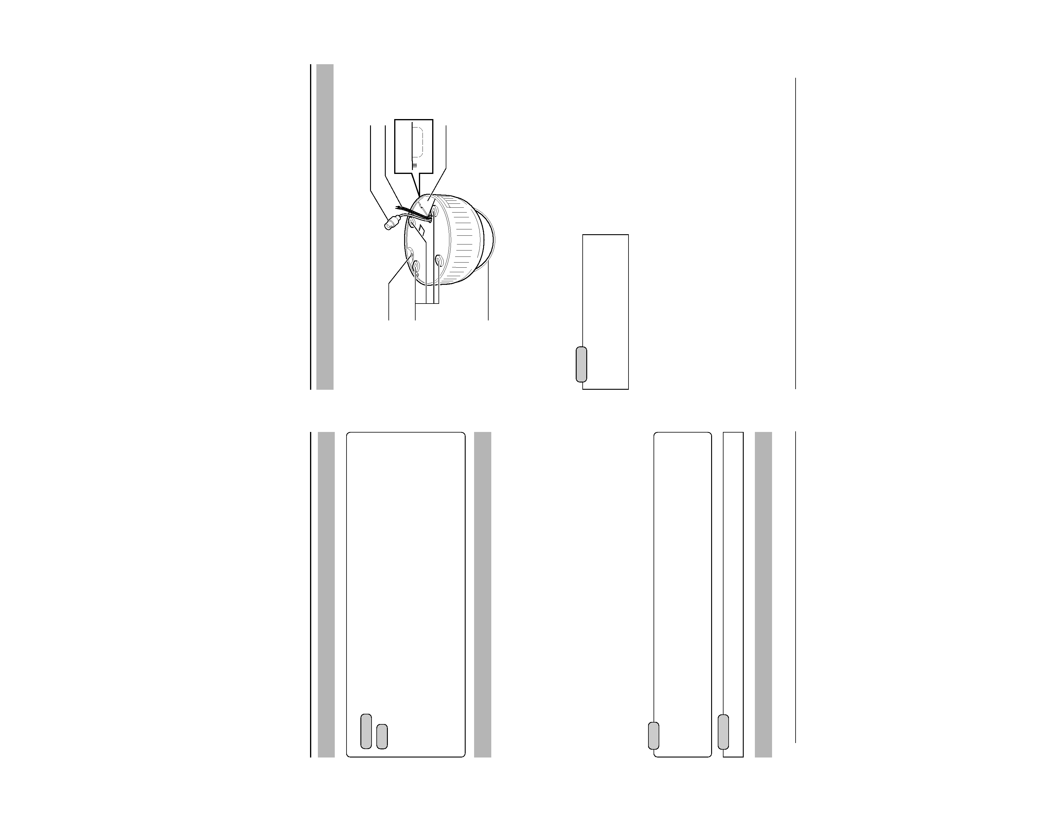
9
Camera
Name and Function of Parts
1 Safety cable mounting hole
This hole is mounted to the ceiling slab or
channel. (Safety cable not included.)
Caution
To avoid unforeseen accidents, attach the
safety cable. Otherwise, there is nothing to
prevent the camera from falling should it
come loose.
2 Mounting holes
These holes are used to mount the camera
body to the ceiling. When using a 4 inch
square electrical box, the 2 holes diagonally
across are used to fix the box in place.
(
Page 21)
3 Dome Cover
The dome cover is fragile. Take care when
handling it.
4 Plate for depressing cables
5 Cable extraction hole
This hole is used to extract cables from the
side of the camera without opening holes in
the ceiling.
6 Input Power cable
To input DC 12 V or AC 24 V power.
The AC 24 V power supply should conform
to the following : Class 2 only (For USA), Iso-
lated power supply only (For Europe).
7 Video signal output connector (BNC)
This BNC connector outputs a composite
video signal. Connect this to the video input
connector of a video monitor, switcher, etc.
(
Page 23)
Output is restricted signal in the NTSC for-
mat only.
2
3
1
7
6
4
5