LCT1635-001A
ENGLISH
DEUTSCH
FRANÇAIS
ITALIANO
ESPAÑOL
SPEAKER UNIT
INSTALLATIONANLEITUNG
: LAUTSPRECHEREINHEIT
MANUEL D'INSTALLATION
: ENCEINTE
MANUALE D'INSTALLAZIONE : UNITÀ DI DIFFUSIONE
MANUAL DE INSTALACION
: UNIDAD DE ALTAVOZ
:
TS-C500SPG
SPEAKER UNIT FOR A JVC PLASMA DISPLAY MONITOR
LAUTSPRECHEREINHEIT FÜR JVC PLASMA BILDSCHIRM
ENCEINTE POUR UN MONITEUR DE VISUALISATION PLASMA
UNITÀ DI DIFFUSIONE PER MONITOR CON SCHERMO AL PLASMA JVC
UNIDAD DE ALTAVOZ PARA MONITOR PLASMA DISPLAY JVC
INSTALLATION MANUAL
ENGLISH
1
Failure to observe what is
mentioned under this symbol
could lead to physical injury and
material damage. Extreme
caution should be exercised.
· Connect the power cord plug to a wall
outlet only after all necessary equipment
has been connected.
Making connections while the power
cord plug is connected to the wall outlet
could result in electric shock.
Failure to observe what is
mentioned under this symbol
could lead to physical injury and
material damage. Extreme
caution should be exercised.
· Do not modify (disassemble) the front
speakers.
This could result in fire or electric shock.
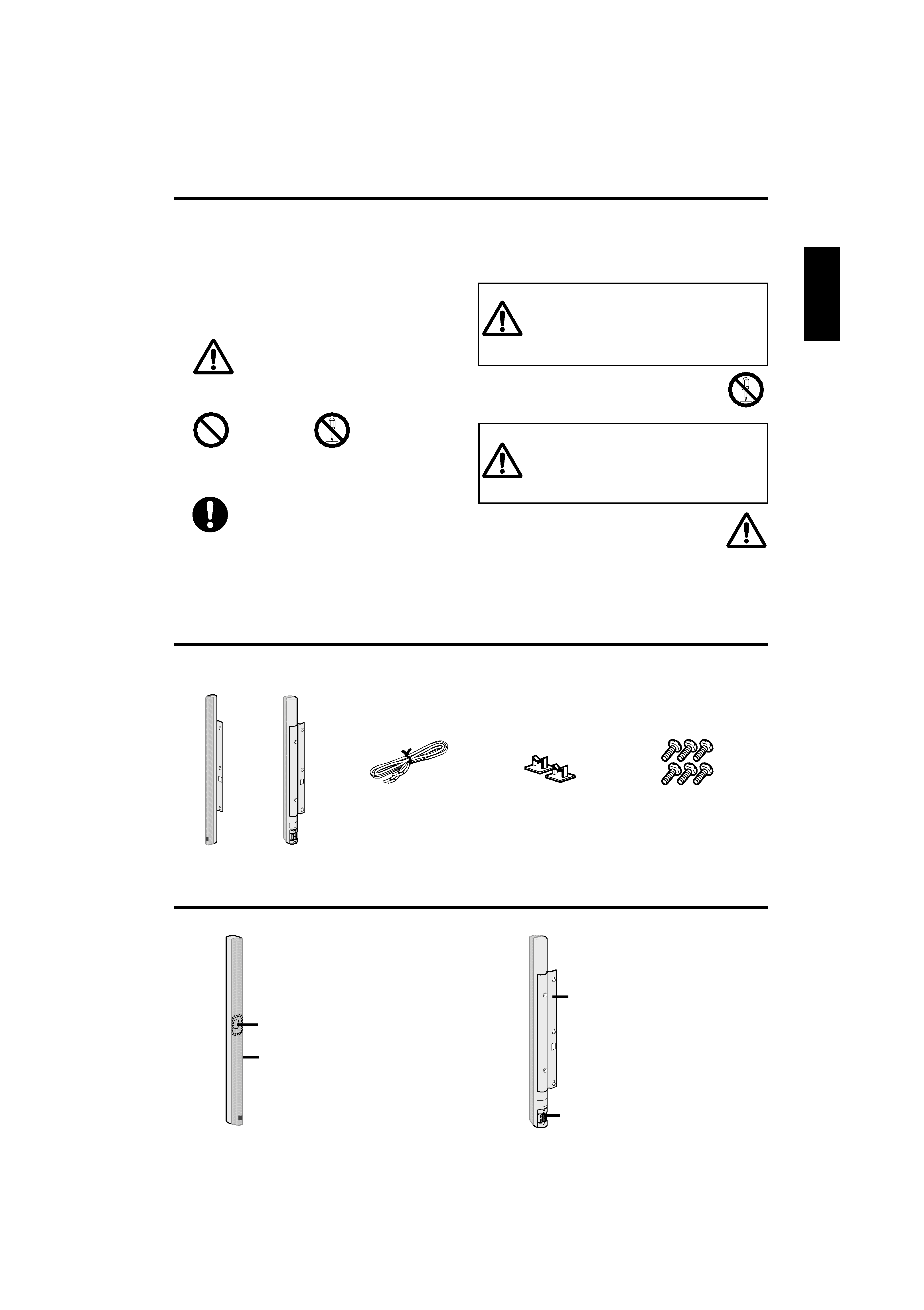
Regarding the "safety precaution" symbols
Various symbols are indicated on the product and in this Installation Manual.
These symbols are provided in order to prevent physical injury and material damage. Be sure you understand the
meaning of the symbols before reading this manual.
SAFETY PRECAUTIONS
WARNING
CAUTION
Explanation of symbols
· This symbol (including a warning) indicates that
CAUTION should be exercised.
· Prohibited actions are indicated by the following symbols.
· Actions that should be performed (compulsory and
instructed actions) are indicated by the following symbol.
General caution
Prohibited
Disassembling
prohibited
General instruction
Names of parts
Front
1 Speaker unit
2 Saran net
This net protects the speaker.
Back
3 Speaker bracket
Attach to the back of the
display.
4 Speaker terminal
Connect this terminal to the
speaker terminal on the
display using the supplied
speaker cords.
Accessories
Check to be sure you have all of the supplied accessories. The number in the parentheses is the quantity of the
pieces supplied. If anything is missing, contact your dealer immediately.
Front speakers (L,R)
Cord clamps (6)
Speaker cords
(1.2 m x 2)
Mounting screws (6)
1
2
4
3
ENGLISH
2
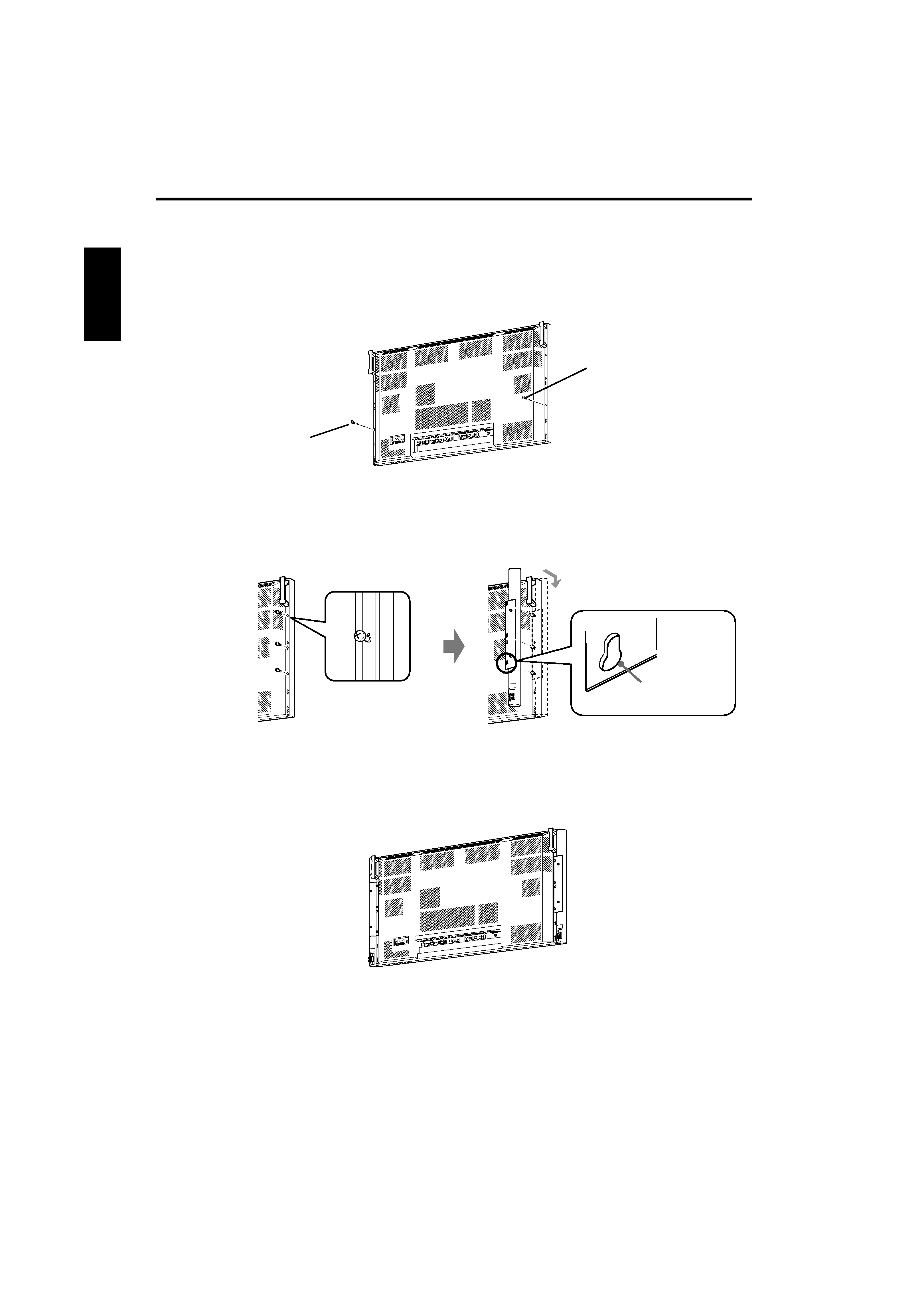
Attaching the front speakers to the GM-X50 series display
Using the speaker brackets, you can attach the front speakers to the side of the display.
· Do not loosen the screws other than the protective screws.
· Use only the supplied mounting screws for attaching the front speakers.
1. Remove the protective screws on the back of the display
with phillips screwdriver.
2. Attach the front speaker to the back of the display.
3. Tighten the mounting screws firmly with phillips screwdriver.
· When moving the display, do not hold the speakers.
· The speakers are not of anti-magnetic type.
Do not place anything susceptible to magnetism, such as a video tape, nearby when setting the speakers.
Protective
screw
Protective
screw
1 Turn the mounting screws with phillips
screwdriver, leaving a length of about 3 mm.
2 Hook the speaker bracket onto three mounting screws
through the screw holes (A), and slide it down.
Screw hole (A)
ENGLISH
3
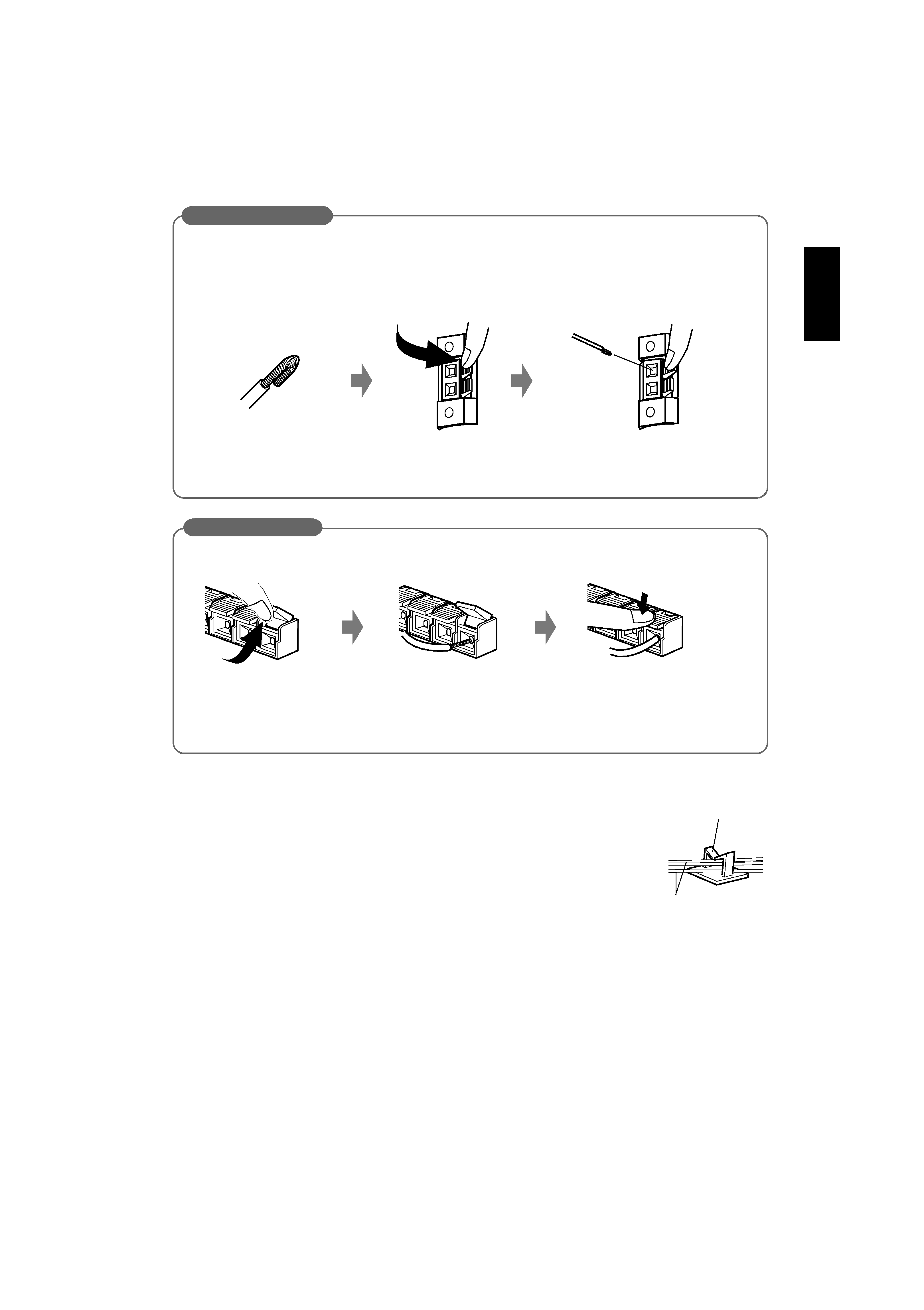
1. Fold the end of each speaker
cord.
Attach to the speakers
2. Press and hold the terminal
clamp.
3. Insert the speaker cord, and
release the finger from the
terminal clamp.
· Connect the cord with black stripes to the
· (black) terminal and the other cord to the ª (red) terminal.
· Be careful that connection of the speaker cords to incorrect polarity terminals (
ª and ·) degrades stereo
feeling and sound qualities.
When you connect the supplied speaker cord to the terminal clamp of the speakers, fold the end of each speaker
cord to avoid short-circuit.
Attach to the display
· Connect the cord with black stripes to the
· (black) terminal and the other cord to the ª (red) terminal.
· Be careful that connection of the speaker cords to incorrect polarity terminals (
ª and ·) degrades stereo
feeling and sound qualities.
· Attach the ferrite core supplied with your display to the speaker cord.
For details, refer to the instruction manual of your display.
1. Open the terminal clamp.
2. Insert the speaker cord.
3. Close the terminal clamp.
Connecting the speaker cord
Cord clamp
Bundling the speaker cords
You can bundle the speaker cords neatly with the supplied cord clamp, as illustrated.
· Stick the cord clamp firmly after removing its protective seal.
· When sticking the cord clamp on the display:
-- Make sure not to block the ventilation hole.
-- Make sure not to prevent attachment of the options, such as a Wall Mounting Unit or
a Ceiling Suspension Unit.
Speaker cord
ENGLISH
4
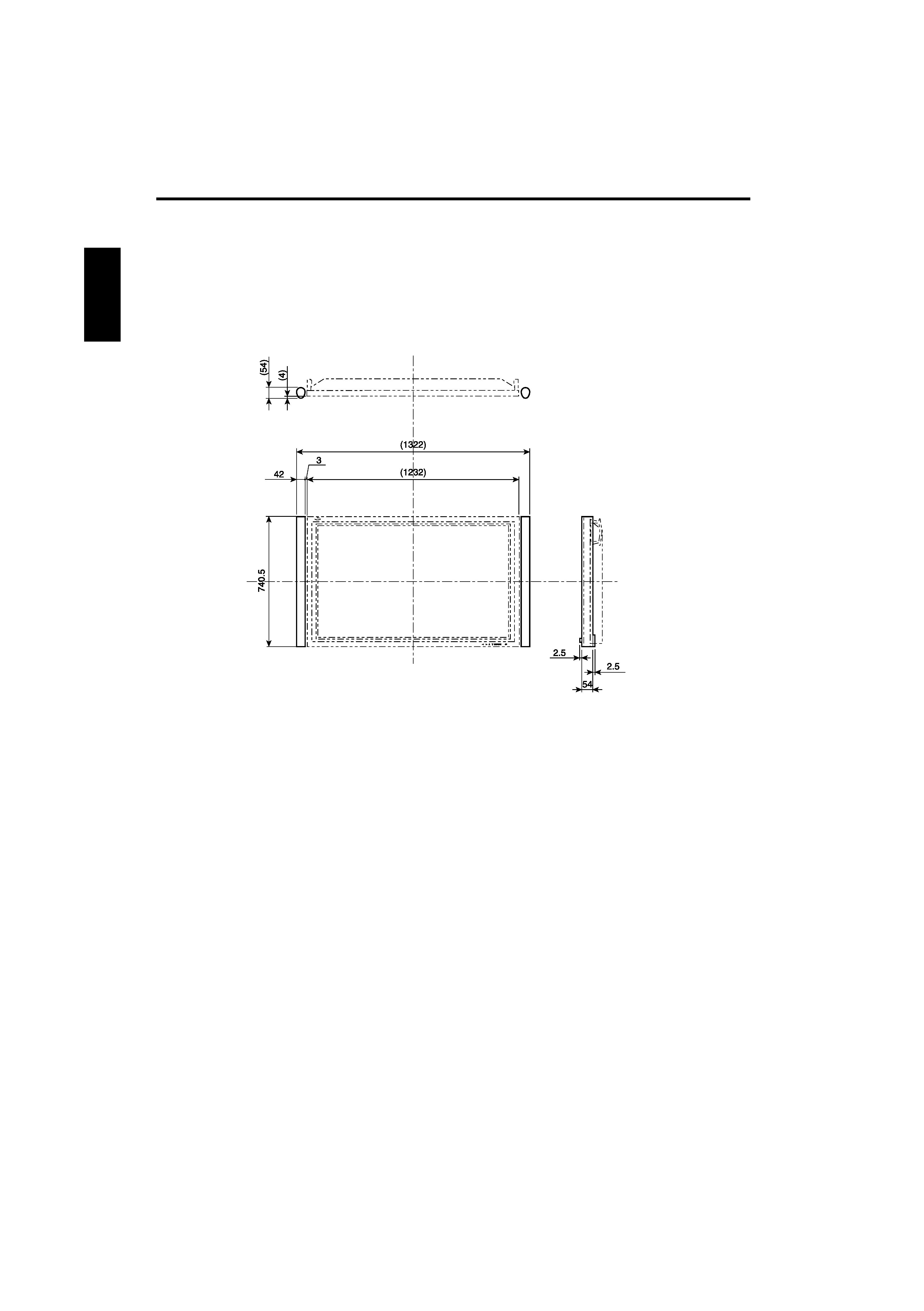
Specifications
· Power Handling Capacity : 3 W
· Impedance
: 6
· Speaker
: 9.5 cm x 1 cm
Direct Drive Speaker, two
· Dimensions
(W x H x D)
: 42 mm x 740.5 mm x 54 mm
(Mass)
: 0.9 kg (for each excluding the speaker bracket)
Top view
Front view
Side view
Unit: mm