TM-2100PN-K
PHASE CHROMA BRIGHT CONTRAST
MENU
INPUT SELECT
VOLUME/SELECT
+
BA
POWER
ON
OFF
Y/C
VIDEO
VIDEO
INSTRUCTIONS
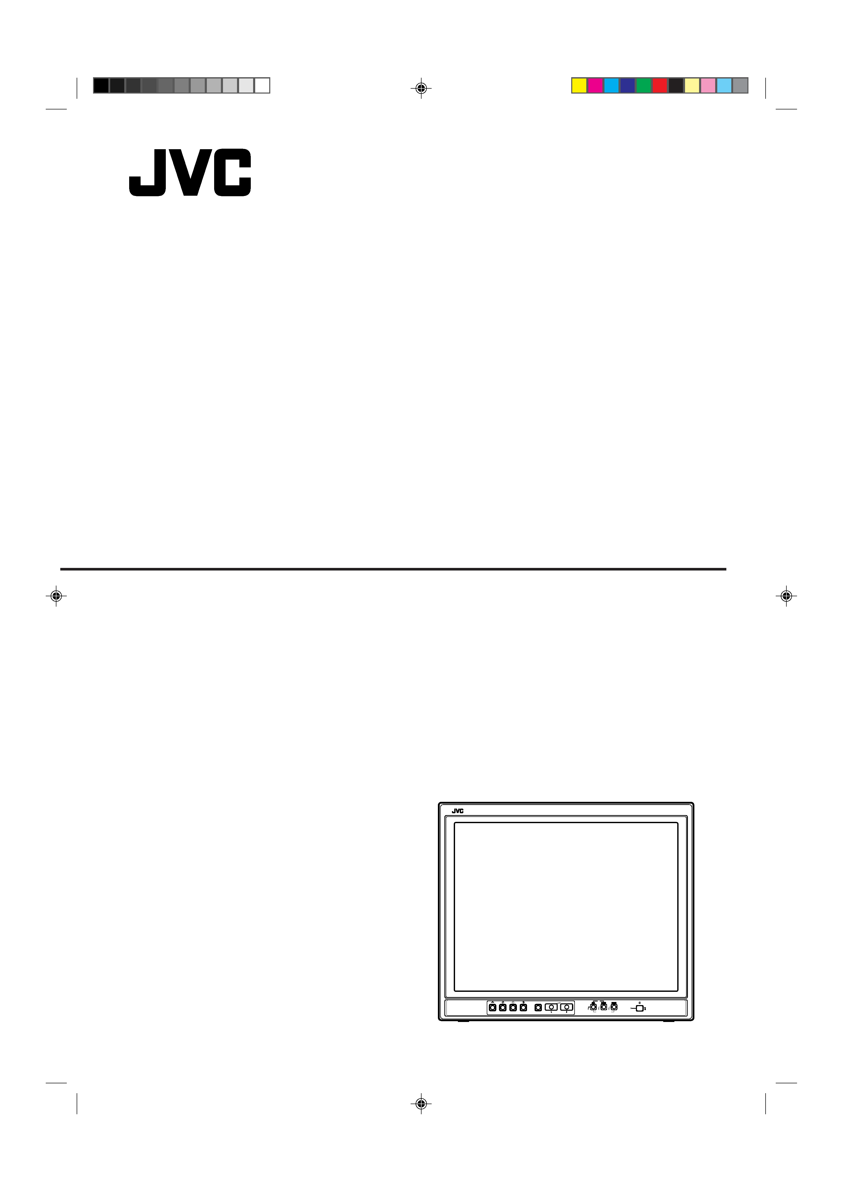
TM-2100PN-K
COLOUR VIDEO MONITOR
LCT0054-002A-H
LCT0054-002A-H
02.07.25, 3:44 PM
1
2
SAFETY PRECAUTIONS
In order to prevent any fatal accidents caused by misoperation
or mishandling the monitor, be fully aware of all the following
precautions.
WARNINGS
To prevent fire or shock hazard, do not expose this
monitor to rain or moisture. Dangerous high voltages
are present inside the unit. Do not remove the back
cover of the cabinet. When servicing the monitor,
consult qualified service personnel. Never try to service
it yourself.
WARNING : THIS APPARATUS
MUST BE EARTHED.
PRECAUTIONS
Use only the power source specified on the unit.
When not using this unit for a long period of time, or when
cleaning it, be sure to disconnect the power plug from the
AC outlet.
Do not allow anything to rest on the power cord. And do not
place this unit where people will tread on the cord. Do not
overload wall outlets or power cords as this can result in a
fire or electric shock.
Avoid using this unit under the following conditions:
in extremely hot, cold or humid places,
in dusty places,
near appliances generating strong magnetic fields,
in places subject to direct sunlight,
in badly ventilated places,
in automobiles with doors closed
Do not cover the ventilation slots while in operation as this
could obstruct the required ventilation flow.
When dust accumulates on the screen surface, clean it with
a soft cloth.
Unplug this unit from the AC outlet and refer servicing to
qualified service personnel under the following conditions:
Machine Noise Information Ordinance 3. GSGV, January
18, 1991: The sound pressure level at the operator
position is equal or less than 70 dB(A) according to ISO
7779.
when the power cord is frayed or the plug is damaged,
if liquid has been spilled into the unit,
if the unit has been dropped or the cabinet has been
damaged,
when the unit exhibits a distinct change in performance.
Do not attempt to service this unit yourself as opening or
removing covers may expose you to dangerous voltage or
other hazards. Always refer servicing to qualified service
personnel.
When replacement parts are required, have the service
personnel verify in writing that the replacement parts he/she
uses have the same safety characteristics as the original
parts. Use of manufacturer's specified replacement parts
can prevent fire, shock, or other hazards.
Upon completion of any servicing or repair work to this unit,
please ask the service personnel to perform the safety check
described in the manufacturer's service literature.
When this unit reaches the end of its useful life, improper
disposal could result in a picture tube implosion. Ask
qualified service personnel to dispose of this unit.
SCREEN BURN
It is not recommended to keep a certain still image displayed on screen for a long time as well as displaying extremely bright
images on screen. This may cause a burning (sticking) phenomenon on the screen of cathode-ray tube. This problem does not
occur as far as displaying normal video playback motion images.
Thank you for purchasing this JVC colour video monitor. Before using it, read and follow
all instructions carefully to take full advantage of the monitor's capabilities.
LCT0054-002A-H
02.07.25, 3:44 PM
2
3
CONTENTS
SAFETY PRECAUTIONS .......................................................................................... 2
CONTROLS AND FEATURES ................................................................................... 4
HOW TO HANDLE BASIC OPERATIONS ................................................................ 6
HOW TO USE THE MENU FUNCTIONS ................................................................... 7
HOW TO INITIALISE THE SETTING ....................................................................... 10
BASIC CONNECTION EXAMPLE ............................................................................ 11
TROUBLESHOOTING ............................................................................................. 13
SPECIFICATIONS .................................................................................................... 14
POWER CONNECTION
WARNING
Do not cut off the main plug from this equipment.
If the plug fitted is not suitable for the power points in your
home or the cable is too short to reach a power point, then
obtain an appropriate safety approved extension lead or
adapter or consult your dealer.
If nonetheless the mains plug is cut off, remove the fuse and
dispose of the plug immediately, to avoid a possible shock
hazard by inadvertent connection to the main supply.
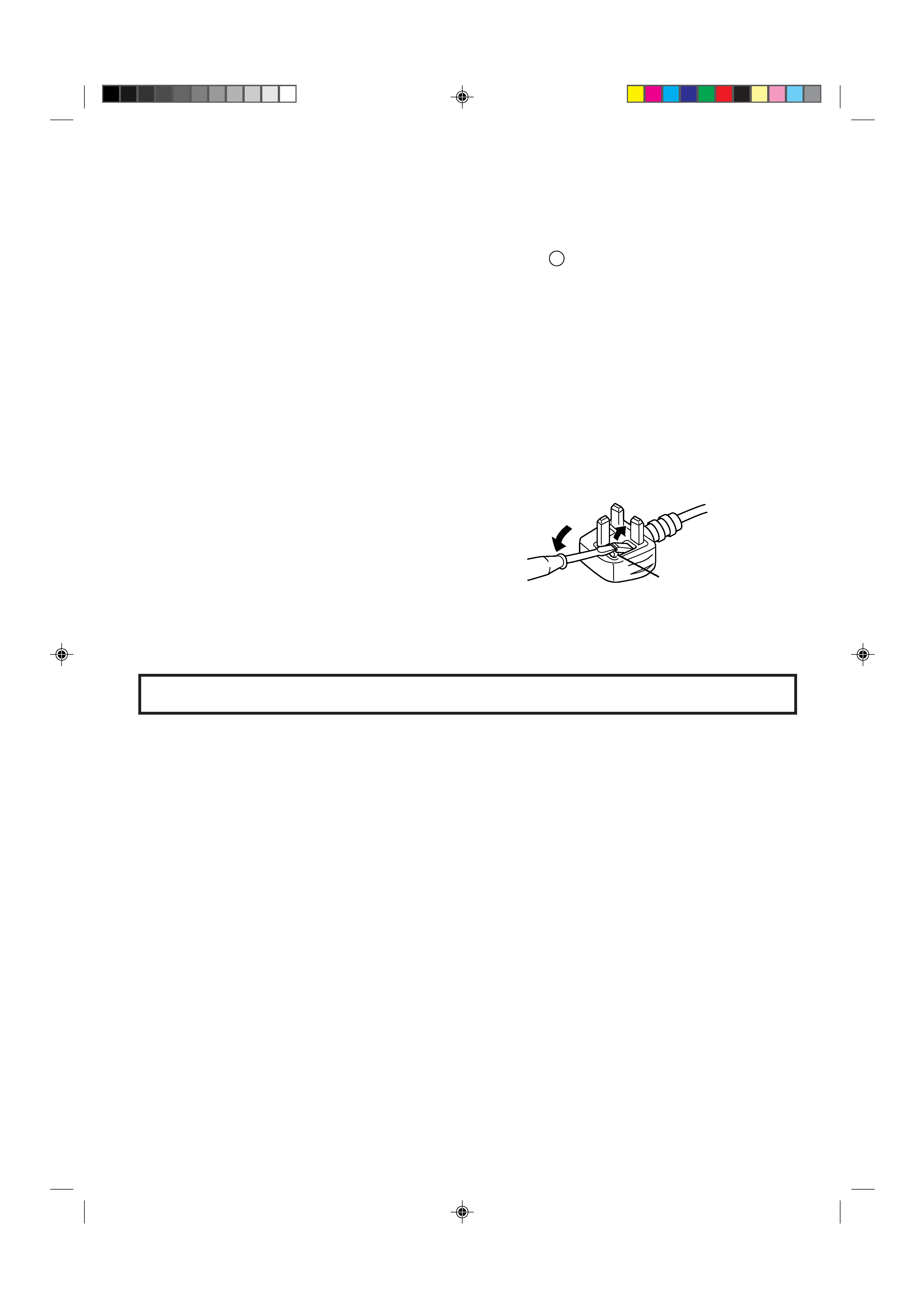
If a new main plug has to be fitted, then follow the instruction
given below:
WARNING:
THIS APPARATUS MUST BE EARTHED.
IMPORTANT.
The wires in the mains lead on this product are coloured in
accordance with the following cord:
Green-and-yellow
: Earth
Blue
: Neutral
Brown
: Live
As these colours may not correspond with the coloured
making identifying the terminals in your plug, proceed as
follows:
The wire which is coloured green-and-yellow must be connected
to the terminal which is marked with the letter E or the safety
earth symbol
or coloured green or green-and-yellow.
The wire which is coloured blue must be connected to the
terminal which is marked with the letter N or coloured black.
The wire which is coloured brown must be connected to the
terminal which is marked with the letter L or coloured red.
When replacing the fuse, be sure to use only a correctly rated
approved type, re-fit the fuse cover.
IF IN DOUBT ---- CONSULT A COMPETENT ELECTRI-
CIAN.
How To Replace The Fuse
Open the fuse compartment with the blade screwdriver, and
replace the fuse.
Fuse
LCT0054-002A-H
02.07.25, 3:44 PM
3
4
TM-2100PN-K
PHASE
CHROMA BRIGHT CONTRAST
MENU
INPUT SELECT
VOLUME/SELECT
+
BA
POWER
ON
OFF
Y/C
VIDEO
VIDEO
1
3
2
4
6
8
5
7
9
11
12 13 14
10
TM-2100PN-K
PHASE CHROMA BRIGHT CONTRAST
MENU
INPUT SELECT
VOLUME/SELECT
+
BA
POWER
ON
OFF
Y/C
VIDEO
VIDEO
15
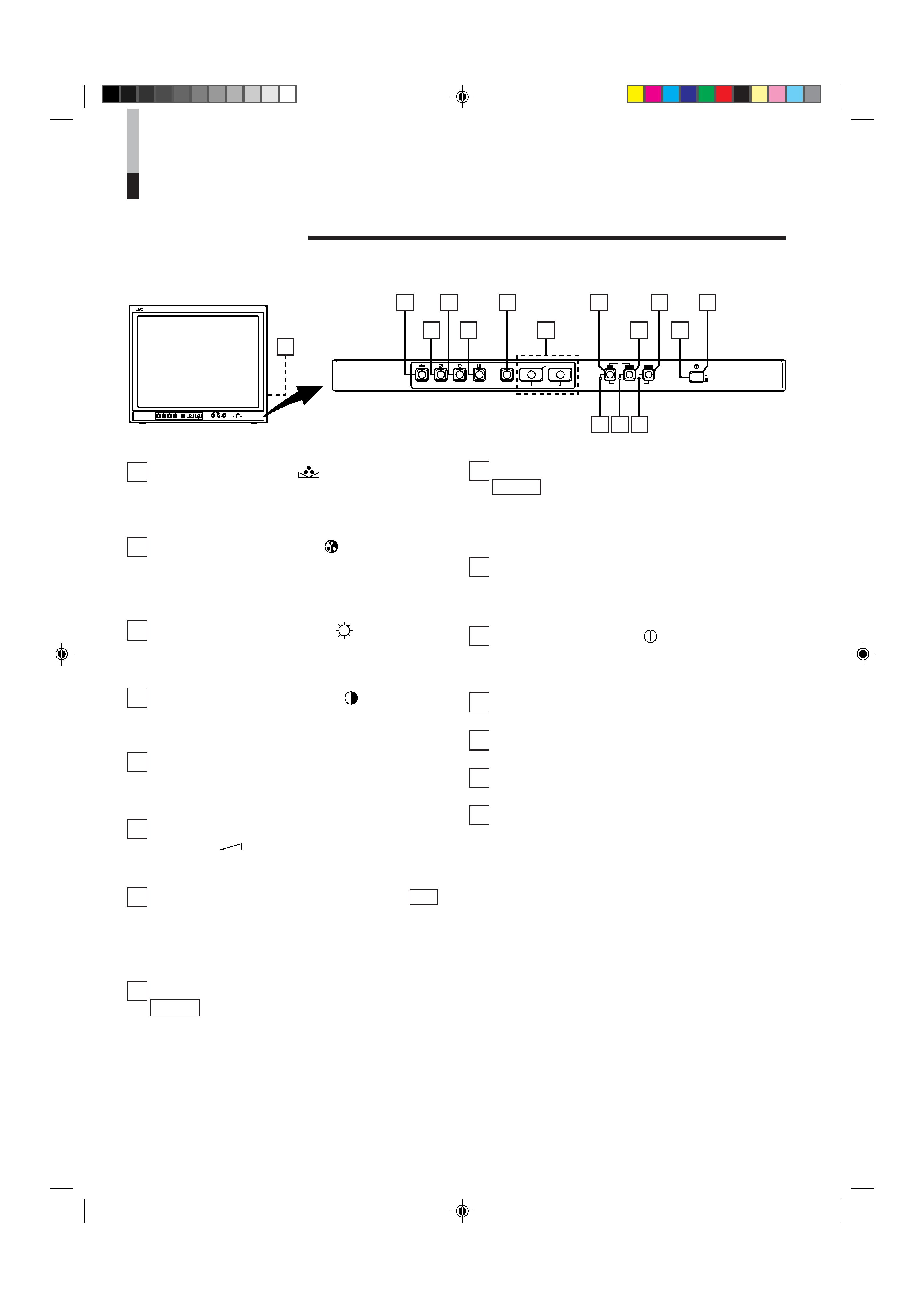
CONTROLS AND FEATURES
FRONT VIEW
<Front Panel>
1 Phase button [PHASE
]
Press this button to set the picture hue adjustment mode.
Adjust the value with the VOLUME/SELECT buttons. Also
used as a control button in the menu function mode.
2 Chroma button [CHROMA
]
Press this button to set the picture colour density adjust-
ment mode. Adjust the value with the VOLUME/SELECT
buttons. Also used as a control button in the menu
function mode.
3 Brightness button [BRIGHT
]
Press this button to adjust picture brightness. Adjust the
value with the VOLUME/SELECT buttons. Also used as a
control button in the menu function mode.
4 Contrast button [CONTRAST
]
Press this button to adjust picture contrast. Adjust the
value with the VOLUME/SELECT buttons. Also used as a
control button in the menu function mode.
5 Menu button [MENU]
Displays and exits the <MENU> screen.
Pressing the PHASE button with the Menu button
depressed will display the <SET-UP MENU> screen.
6 Volume/Select buttons [VOLUME/
SELECT
+]
Adjusts the speaker volume. Also used as a control button
in the menu function mode.
7 Input B (Y/C) button [INPUT SELECT B Y/C ]
Selects the video signal input to the VIDEO B (Y/C)
terminal (mini DIN 4 pin connector) and the audio signal
input to the AUDIO B terminal (RCA connector) on the
rear panel. When selected, the input B (Y/C) indicator @
lights.
8 Input B (VIDEO) button [INPUT SELECT B
VIDEO ]
Selects the video signal input to the VIDEO B terminal
(BNC connector) and the audio signal input to the AUDIO
B terminal (RCA connector) on the rear panel. When
selected, the input B (VIDEO) indicator # lights.
9 Input A (VIDEO) button [INPUT SELECT A
VIDEO ]
Selects the video signal input to the VIDEO A terminal
(BNC connector) and the audio signal input to the AUDIO
A terminal (RCA connector) on the rear panel. When
selected, the input A (VIDEO) indicator $ lights.
10 Power indicator
Lights in green when the power is ON.
Lit
: When the power is on.
Unlit : When the power is off.
11 Power switch [POWER
]
Press this switch to turn the power on or off.
_ ON : Power is turned on.
-- OFF : Power is turned off.
12 Input B (Y/C) indicator
Lights in green when the Input B (Y/C) is selected.
13 Input B (VIDEO) indicator
Lights in green when the Input B (VIDEO) is selected.
14 Input A (VIDEO) indicator
Lights in green when the Input A (VIDEO) is selected.
15 Speaker
A built-in speaker is located inside the right side panel
when the monitor is viewed from the front.
LCT0054-002A-H
02.07.25, 3:44 PM
4
5
OUT
IN
A
B
VIDEO
A
B
AUDIO
REMOTE
OUT
IN
OUT
IN
OUT
IN
IN
OUT
Y/ C
OUT
IN
22
23
OUT
IN
A
B
VIDEO
A
B
AUDIO
REMOTE
OUT
IN
OUT
IN
OUT
IN
IN
OUT
Y/ C
OUT
IN
16
17
18
19
20
21
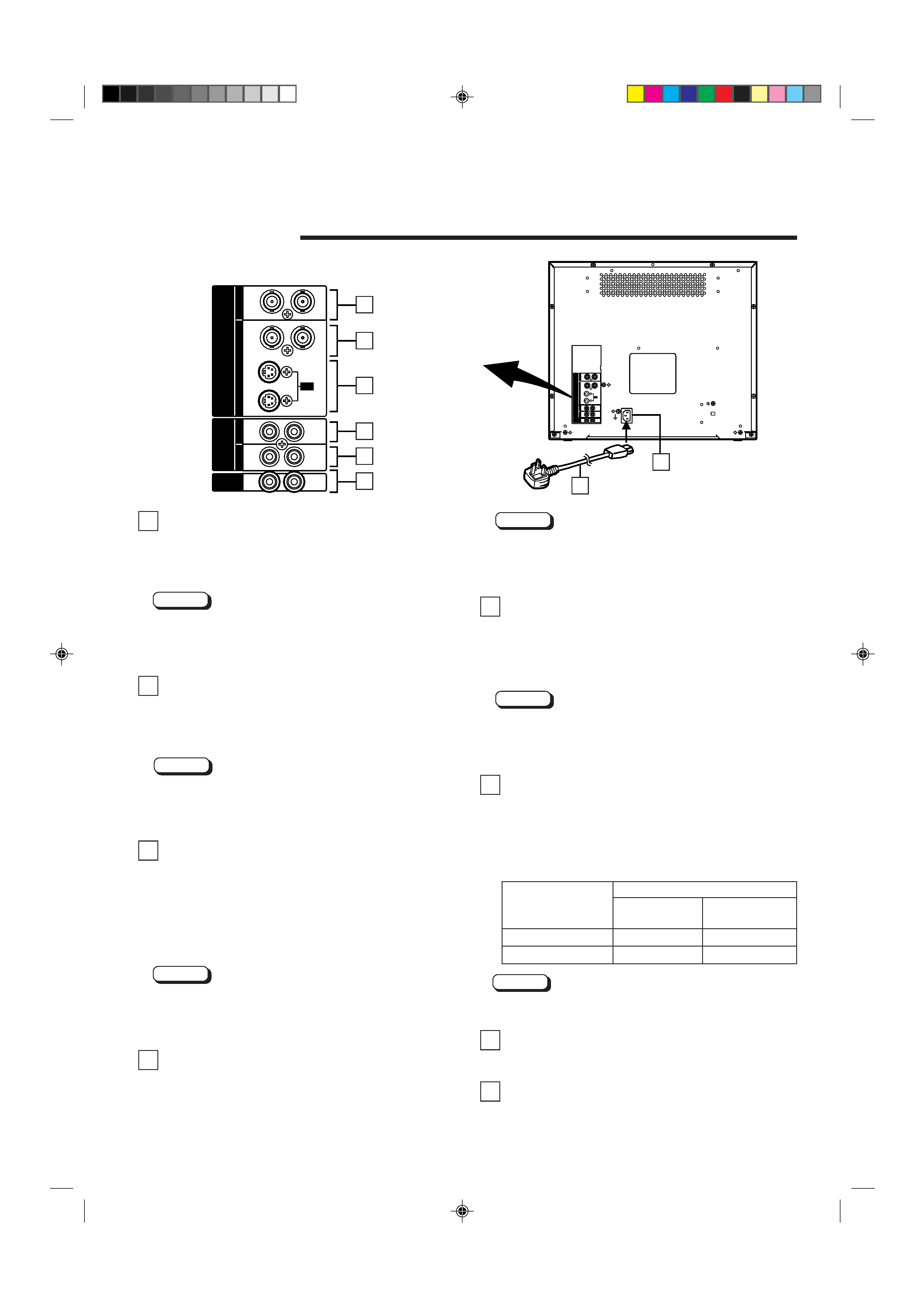
16 Video A terminals [VIDEO A IN/OUT]
Video signal input (IN) and output (OUT) terminals.
The output terminal is bridge-connected.
IN
: Video signal input terminal
OUT : Bridge-connected video signal output terminal
Notes:
* For corresponding audio signals, use the AUDIO A
terminals (.
* Also refer to the BASIC CONNECTION EXAMPLE on
pages 11 and 12.
17 Video B terminals [VIDEO B IN/OUT]
Video signal input (IN) and output (OUT) terminals.
The output terminal is bridge-connected.
IN
: Video signal input terminal
OUT : Bridge-connected video signal output terminal
Notes:
* For corresponding audio signals, use the AUDIO B
terminals ).
* Also refer to the BASIC CONNECTION EXAMPLE on
pages 11 and 12.
18 Video B (Y/C) terminals [VIDEO B Y/C IN/
OUT]
Y/C (S-Video) signal input (IN) and output (OUT) termi-
nals.
The output terminal is bridge-connected.
IN
: Y/C-separated (S-video) signal input terminal
OUT : Bridge-connected Y/C-separated (S-video) signal
output terminal
Notes:
* For corresponding audio signals, use the AUDIO B
terminals ).
* Also refer to the BASIC CONNECTION EXAMPLE on
pages 11 and 12.
19 Audio A terminal [AUDIO A IN/OUT]
Input (IN) and output (OUT) terminals for the audio signal
corresponding the VIDEO A terminals ^. The output
terminal is bridge-connected.
IN
: Audio signal input terminal
OUT : Bridge-connected audio signal output terminal
REAR VIEW
<Rear Panel>
To AC outlet
(230 V AC, 50 Hz/60 Hz)
Notes:
* For corresponding video signals, use the VIDEO A
terminal ^.
* Also refer to the BASIC CONNECTION EXAMPLE on
pages 11 and 12.
20 Audio B terminals [AUDIO B IN/OUT]
Input (IN) and output (OUT) terminals for the audio signals
corresponding to the VIDEO B terminals & or VIDEO B (Y/
C) terminals *. The output terminal is bridge-connected.
IN
: Audio signal input terminal
OUT : Bridge-connected audio signal output terminal
Notes:
* For corresponding video signals, use the VIDEO B
terminals & or VIDEO B (Y/C) terminals *.
* Also refer to the BASIC CONNECTION EXAMPLE on
pages 11 and 12.
21 Remote terminals [REMOTE IN/OUT]
Input (IN) and output (OUT) terminals for external control.
The output terminal is bridge-connected. External control
is available either to select the ASPECT RATIO or to
select ON or OFF in BRIGHTNESS P.S. function mode.
Set the external control in the <SET-UP MENU> screen
mode.
Note:
* Also refer to the BASIC CONNECTION EXAMPLE on
pages 11 and 12.
22 AC Inlet [AC IN]
Power input connector. Connect the provided AC power
cord q to an AC outlet (230 V AC, 50 Hz/60 Hz).
23 Power cord
Connects the provided power cord (230 V AC, 50 Hz/
60 Hz) to the AC IN connector.
External control switch
Open circuit
Short circuit
(open)
(short)
ASPECT RATIO
43 (4:3)
169 (16:9)
BRIGHTNESS P.S.
OFF
ON
External control
functions
LCT0054-002A-H
02.07.25, 3:44 PM
5