TK-C655
TK-C676
TK-C655/TK-C676
DOME
TYPE
CAMERA
DOME TYPE CAMERA
DOME-FARBKAMERA
CAMERA DE TYPE DOME
CÁMARA TIPO CÚPULA
TELECAMERA A DUOMO
INSTRUCTIONS
(B)
M
LWT0201-001A-H CDROM
DEUTSCH
FRANÇAIS
ESP
AÑOL
IT
ALIANO
ENGLISH

E-2
IMPORTANT SAFEGUARDS
1. Read all of these instructions.
2. Save these instructions for later use.
3. All warnings on the product and in the operating instructions should be adhered to.
4. Unplug this appliance system from the wall outlet before cleaning. Do not use liquid cleaners or aerosol cleaners. Use
a damp cloth for cleaning.
5. Do not use attachments not recommended by the appliance manufacturer as they may cause hazards.
6. Do not use this appliance near water for example, near a bathtub, washbowl, kitchen sink, or laundry tub, in a wet
basement, or near a swimming pool, etc.
7. Do not place this appliance on an unstable cart, stand, or table. The appliance may fall,
causing serious injury to a child or adult, and serious damage to the appliance.
Use only with a cart or stand recommended by the manufacturer, or sold with the appliance.
Wall or shelf mounting should follow the manufacturer's instructions, and should use a
mounting kit approved by the manufacturer.
An appliance and cart combination should be moved with care. Quick stops, excessive
force, and uneven surfaces may cause the appliance and cart combination to overturn.
8. Slots and openings in the cabinet and the back or bottom are provided for ventilation, and to
insure reliable operation of the appliance and to protect it from overheating, these openings
must not be blocked or covered. The openings should never be blocked by placing the appliance on a bed, sofa, rug,
or other similar surface. This appliance should never be placed near or over a radiator or heat register. This appliance
should not be placed in a built-in installation such as a bookcase unless proper ventilation is provided.
9. This appliance should be operated only from the type of power source indicated on the marking label. If you are not
sure of the type of power supplied to your home, consult your dealer or local power company. For appliance designed
to operate from battery power, refer to the operating instructions.
10. This appliance system is equipped with a 3-wire grounding type plug (a plug having a third (grounding) pin). This plug
will only fit into a grounding-type power outlet. This is a safety feature. If you are unable to insert the plug into the
outlet, contact your electrician to replace your obsolete outlet. Do not defeat the safety purpose of the grounding plug.
11. For added protection for this product during a lightning storm, or when it is left unattended and unused for long
periods of time, unplug it form the wall outlet and disconnect the antenna or cable system. This will prevent damage to
the product due to lightning and power-line surges.
12. Do not allow anything to rest on the power cord. Do not locate this appliance where the cord will be abused by
persons walking on it.
13. Follow all warnings and instructions marked on the appliance.
14. Do not overload wall outlets and extension cords as this can result in fire or electric shock.
15. Never push objects of any kind into this appliance through cabinet slots as they may touch dangerous voltage points
or short out parts that could result in a fire or electric shock. Never spill liquid of any kind on the appliance.
16. Do not attempt to service this appliance yourself as opening or removing covers may expose you to dangerous
voltage or other hazards. Refer all servicing to qualified service personnel.
17. Unplug this appliance from the wall outlet and refer servicing to qualified service personnel under the following condi-
tions:
a. When the power cord or plug is damaged or frayed.
b. If liquid has been spilled into the appliance.
c. If the appliance has been exposed to rain or water.
d. If the appliance does not operate normally by following the operating instructions. Adjust only those controls that
are covered by the operating instructions as improper adjustment of other controls may result in damage and will
often require extensive work by a qualified technician to restore the appliance to normal operation.
e. If the appliance has been dropped or the cabinet has been damaged.
f.
When the appliance exhibits a distinct change in performance this indicates a need for service.
18. When replacement parts are required, be sure the service technician has used replacement parts specified by the
manufacturer that have the same characteristics as the original part. Unauthorized substitutions may result in fire,
electric shock, or other hazards.
19. Upon completion of any service or repairs to this appliance, ask the service technician to perform routine safety
checks to determine that the appliance is in safe operating condition.
PORTABLE CART WARNING
(symbol provided by RETAC)
S3125A
These are general IMPORTANT SAFEGUARDS and certain items may not apply to all appliances.

E-3
ENGLISH
Contents
Introduction
Features ............................................................................................................................................................................. 4
Provided Accessories ......................................................................................................................................................... 4
Safety Precautions ............................................................................................................................................................. 5
Precautions for Correct Operation ...................................................................................................................................... 6
Connections & Installation
Controls, Connectors and Indicators .................................................................................................................................. 8
A Multi-Drop Communication System .............................................................................................................................. 10
Point-to-Point Communication System ............................................................................................................................. 12
Switch Settings ................................................................................................................................................................. 14
Cable Connections ........................................................................................................................................................... 16
Attaching the Ceiling Mount ............................................................................................................................................. 18
Attaching the Camera ....................................................................................................................................................... 18
Setting Up the Camera using an RM-P2580
Setup Procedure .............................................................................................................................................................. 20
Menu Screen Flow ............................................................................................................................................................ 21
CAMERA FUNCTION1 Screen ........................................................................................................................................ 22
CAMERA FUNCTION2 Screen ........................................................................................................................................ 23
CAMERA TITLE/ALARM Screen ...................................................................................................................................... 24
CAMERA VIDEO ADJUSTMENT Screen ........................................................................................................................ 26
CAMERA ALC Screen ...................................................................................................................................................... 26
HOME MOTION DETECT Screen .................................................................................................................................... 28
AUTO PAN/PATROL/TRACE Screen ................................................................................................................................ 29
POSITION FUNCTION SET Screen ................................................................................................................................ 30
FACTORY SETTINGS Screen .......................................................................................................................................... 31
PRIVATE MASK Setup ..................................................................................................................................................... 32
CAMERA TITLE Setup ..................................................................................................................................................... 33
AREA TITLE Setup ........................................................................................................................................................... 34
ALARM TITLE Setup ........................................................................................................................................................ 35
HOME MOTION DETECT Setup ...................................................................................................................................... 36
AUTO PAN Setup ............................................................................................................................................................. 37
AUTO PATROL Setup ....................................................................................................................................................... 38
AUTO TRACE Setup ........................................................................................................................................................ 39
POSITION TITLE Setup ................................................................................................................................................... 40
AUTO RETURN Setup ..................................................................................................................................................... 41
Others
Attaching a Ceiling Flush Mount Bracket (Optional WB-S575) ......................................................................................... 42
Removing a Ceiling Flush Mount Bracket (Optional WB-S575) ....................................................................................... 44
Troubleshooting ................................................................................................................................................................ 45
Specifications ................................................................................................................................................................... 46
Thank you for purchsing this product.
(These instructions are for TK-C655E, TK-C676E)
Before beginning to operate this unit, please read the instruction manual carefully in order to make sure that the best possible
performance is obtained.
E-4
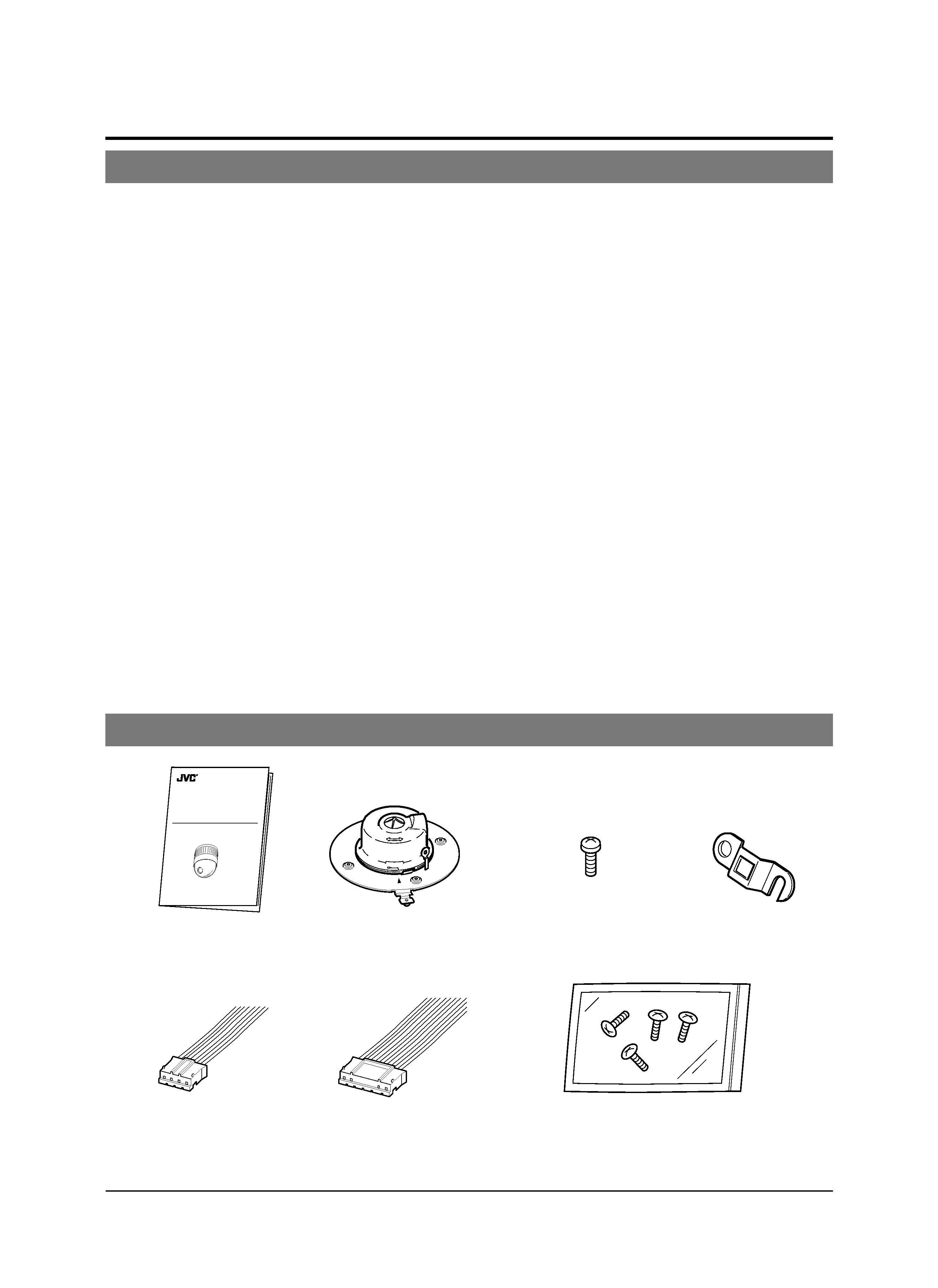
Provided Accessories
Features
DSP with a wide dynamic range
Even objects that have a large difference in brightness can
be monitored clearly.
Day/night surveillance
When the light is low, the camera pictures can be switched
automatically to black and white pictures.
The camera is also compatible with IR illumination (wave-
length 850 nm to 880 nm).
Private masking facility
When the camera target area contains an area that is re-
quired to be hidden the camera can be set accordingly in
order to mask it.
High-speed pan/tilt table
The high-speed rotating table with a horizontal panning
speed of 300°/sec. and a vertical tilting speed of 180°/sec.
makes it possible to recall a preset position quickly.
High-sensitivity CCD and bright zoom lens
TK-C655: The CCD features an improved sensitivity of near-
ly 70% over the previous model and the zoom
lens has a large aperture ratio of f1.6 (at WIDE
end). These features provide the camera with a
high sensitivity of 2.0 lx in the color mode (50%
output, AGC 20 dB).
TK-C676: The CCD features an improved sensitivity of near-
ly 70% over the previous model and the zoom
lens has a large aperture ratio of f1.4 (at WIDE
end). These features provide the camera with a
high sensitivity of 0.5 lx in the color mode (25%
output, AGC 20 dB, WIDE end, electronic sense
up x2).
Introduction
TK-C655
TK-C676
DOME TYPE CAMERA
INSTRUCTIONS
(B)
LWT0003-001A-H
Instructions
Ceiling mount
Screw
(M3 × 12 mm)
For cable plate
Cable plate
4P Alarm cable
6P Alarm cable
Screws (M 4 x 12 mm)
For the ceiling flush mount bracket
Optical zoom lens (TK-C655 only)
Detailed surveillance can be performed with the approx.
x25 optical zoom lens.
Optical + electronic zooming (TK-C676 only)
The x27 optical zoom lens and x10 electronic zoom circuit-
ry allows the camera to be used even in surveillance situa-
tions in which the object is very small.
Simplified waterproof design (TK-C676 only)
The simplified waterproof design (IEC529) of the camera
allows it to be installed in many locations, including under
eaves, provided that it is not subjected to direct water splash.
(However, note that the camera cannot be used outdoors.)

E-5
ENGLISH
Safety Precautions
WARNING
· Install the unit on a strong and stable surface.
This unit has been designed to revolve at high speed. Due to
its weight (about 2.4 kg) and the vibrations it may be subject-
ed to, the camera must be mounted to a sturdy and stable
material. If the ceiling material lacks strength, for example it
is made of a decorative laminated material or plasterboard,
then the mount should be reinforced using materials such as
veneered plywood. If such reinforcement is inadequate im-
ages may fluctuate due to vibration or, in the worst case, the
camera may fall and cause a serious accident should there
be anyone below it.
·For installation, use the provided ceiling mount and the op-
tional flush mounted ceiling bracket, which is sold separately.
When installing this device the provided ceiling mount and
the optional flush mounted ceiling bracket, which is sold sep-
arately should be used. Also be sure to connect the drop
prevention wire and tighten all screws and nuts firmly.
·Power the unit with the rated power voltage.
The power rating for this unit is 24 V AC, 50 Hz/60 Hz. If a
power above this rating is supplied, a malfunction will occur
or, in the worst case, smoke or fire may be produced.
· This unit offers a certain degree of protection against any
damage either to itself or to its connection cable that might
result from indirect lightning strikes, but it is not capable of
preventing all damage by lightning strikes. For example it is
not protected against a direct lightning strike. If lightning dam-
age can be expected in the place where the unit is installed,
be sure to take countermeasures by adding an arrester to
the connection cable, etc.
WARNING:
TO REDUCE THE RISK OF FIRE OR
ELECTRIC SHOCK, DO NOT EXPOSE THIS
APPLIANCE TO RAIN OR MOISTURE.
AVERTISSEMENT:
POUR EVITER LES RISQUES D'INCENDIE OU
D'ELECTROCUTION, NE PAS EXPOSER
L'APPAREIL A L'HUMIDITE OU A LA PLUIE.
CAUTION
· Installation of this unit requires special skills. Please be sure
to consult your dealer about installation procedures.
If the mounting screws or nuts are not tightened sufficiently,
the camera may fall from its installation location. Be sure to
tighten the mounting nuts firmly to prevent this happening.
· Inspect the unit periodically.
Check periodically for any deterioration of the mount sec-
tions or loosening of screws due to vibration and ensure that
there is no likelihood of the unit dropping.