SERVICE MANUAL
POWERED SUBWOOFER
No.20863
Jul. 2000
COPYRIGHT
2000 VICTOR COMPANY OF JAPAN, LTD.
d in Japan
07(V)
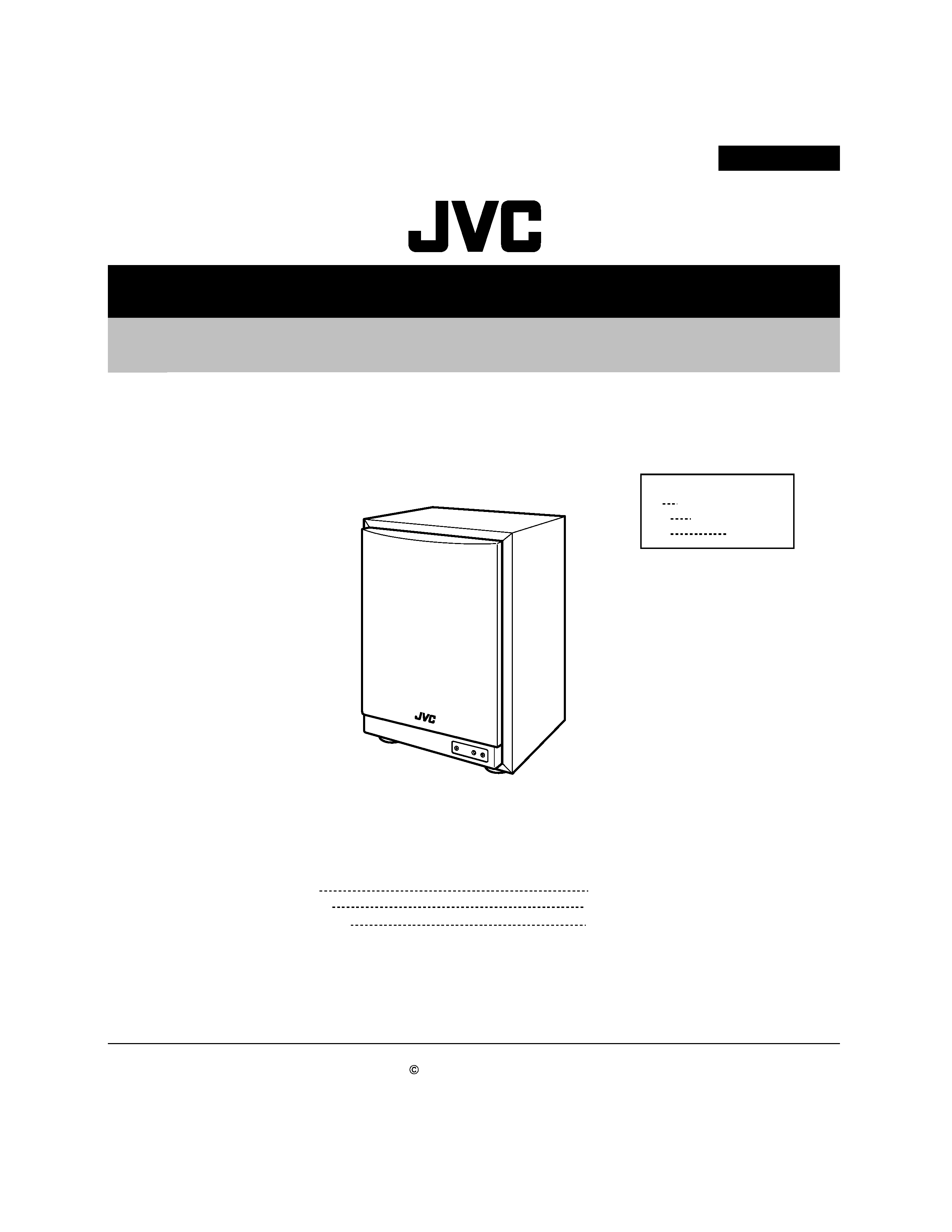
SP-PW880
SP-PW880
Contents
Safety Precautions
Disassembly method
Description of major ICs
1-2
1-3
1-6
Area Suffix
E
EN
US
Continental Europe
Northern Europe
Singapore
SP-PW880
!
Burrs formed during molding may be left over on some parts of the chassis. Therefore,
pay attention to such burrs in the case of preforming repair of this system.
Safety precaution
1-2
SP-PW880
1-3
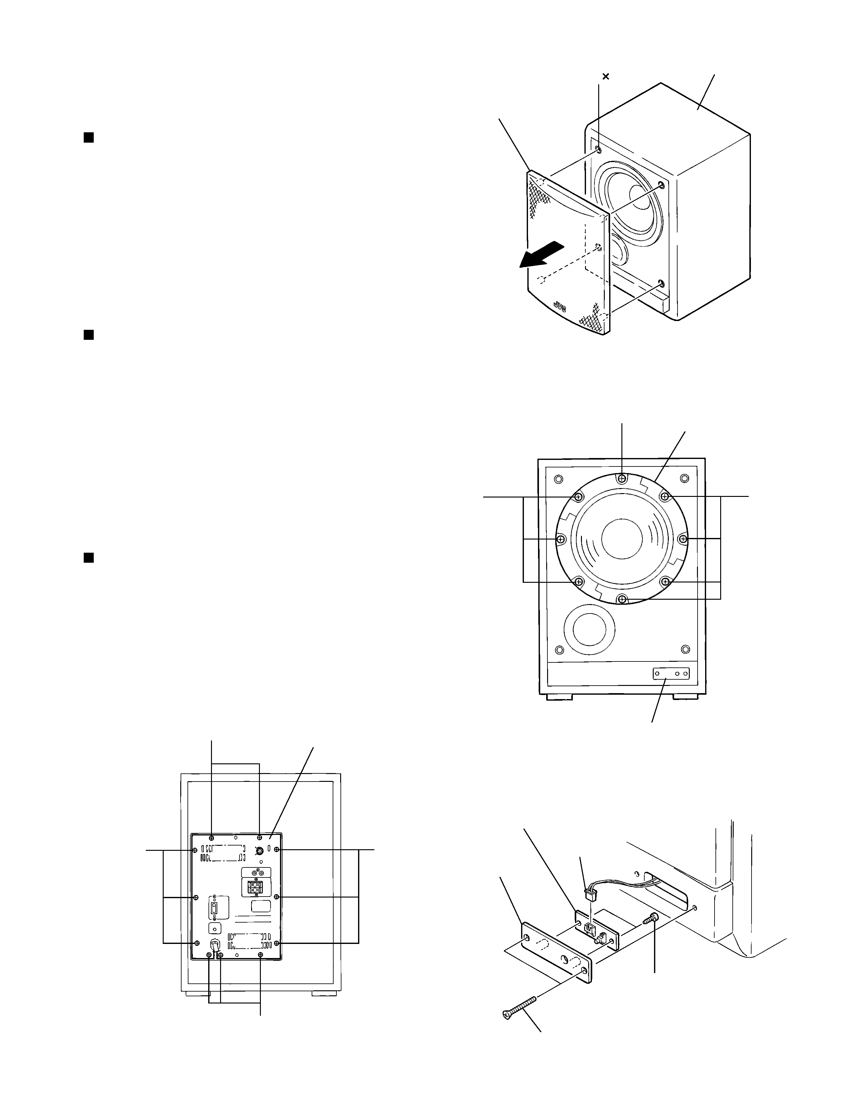
Remove the saran board assembly from the cabinet
assembly while releasing the four corner joints
toward the front.
Remove the eight screws A attaching the speaker.
Disconnect the fasten connected to the speaker
terminal on the back of the speaker.
1.
2.
3.
Disassembly method
<Main body>
Removing the speaker (See Fig.1 and 2)
Remove the two screws B
attaching the LED
indicator board assembly on the front side of the
speaker box.
Disconnect the harness from connector CN404 on
the LED indicator board assembly.
Remove the two screws C and the panel.
1.
2.
3.
Removing
the
LED
indicator
board
assembly (See Fig.3)
Removing the amplifier assembly
(See Fig.4)
Remove the eleven screws D attaching the amplifier
board on the back of the body.
Disconnect each relay harness connected to the
speaker and the LED indicator board.
1.
2.
Fig.1
Fig.2
Fig.3
Fig.4
Joint 4
Cabinet assembly
Saran board assembly
Speaker
A
A
A
LED indicator board assembly
Harness
LED indicator board assembly
Panel
B
C
Amplifier board
D
D
DD
SP-PW880
1-4
Pull out the volume knob from the amplifier.
Remove the three screws E and the two screws F
on the amplifier.
1.
2.
<Amplifier>
Removing the cover (See Fig.5)
Cut off the band under the input board assembly.
Disconnect the harness from connector CN851.
Remove the two screws G
attaching the input
amplifier / filter board assembly. Pull and disconnect
connector CN811 from the body.
1.
2.
3.
Removing the Input board assembly
(See Fig.6)
Removing the amplifier board assembly
(See Fig.7 and 8)
Prior to performing procedure, remove the input
amplifier / filter board assembly.
Disconnect the harness from connector CN891 and
CN881 on the amplifier board assembly.
Remove the six screws H
attaching the amplifier
board assembly.
Remove the two screws I attaching the heat sink 1
and the two screws J
attaching the heat sink 2
respectively.
1.
2.
3.
Fig.5
Fig.6
Fig.7
Fig.7
Volume knob
Cover
F
(Only US)
E
Input board
assembly
CN811
CN851
G
Band
Amplifier board assembly
CN891
CN881
H
H
H
H
Heat sink 2
Heat sink 1
Amplifier board assembly
J
I
I
J
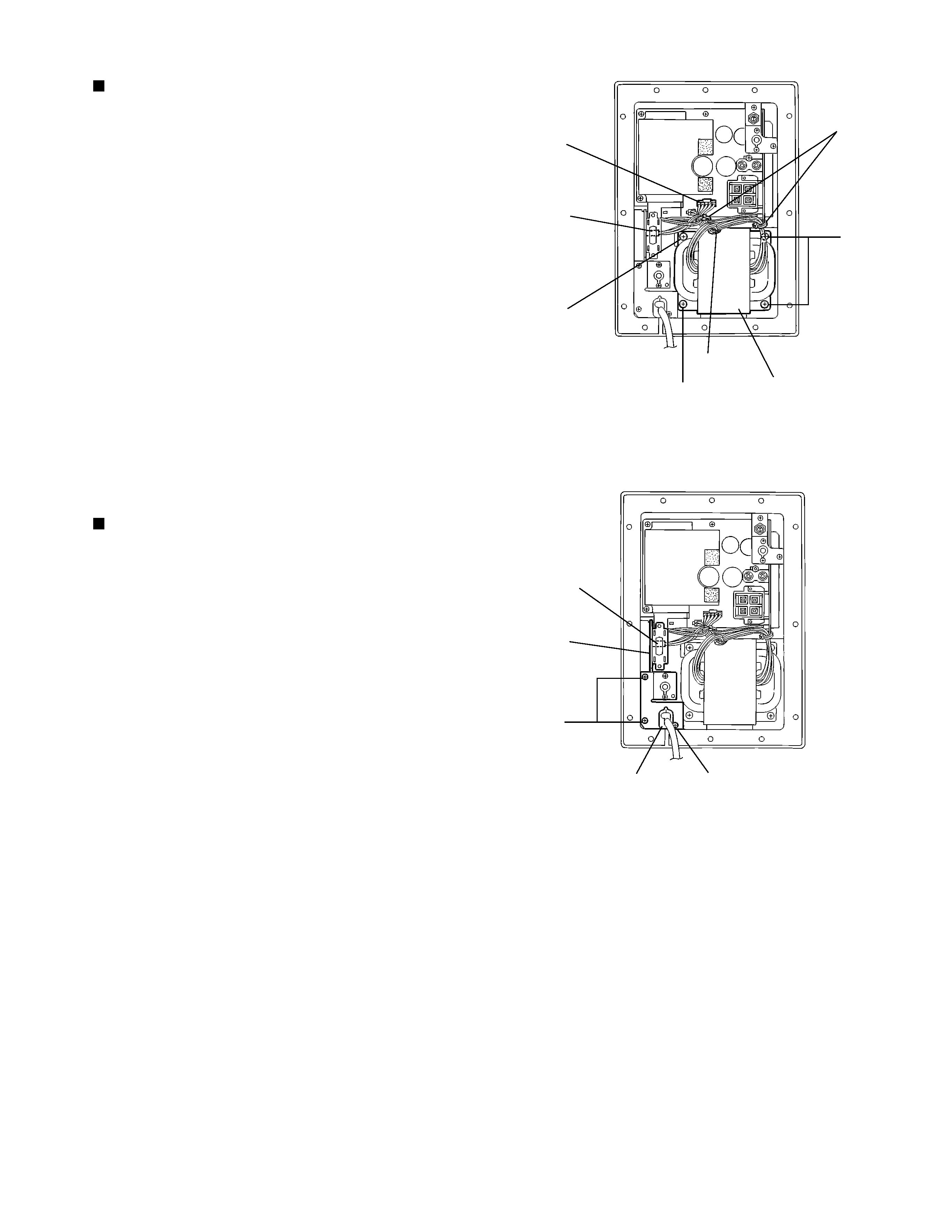
SP-PW880
1-5
Cut off the three bands fastening the harnesses
extending from the transformer assembly.
Disconnect the harness from connector CN891 on
the amplifier board assembly and from CN899 on the
power board assembly.
Remove the four screws K attaching the transformer
assembly.
1.
2.
3.
Removing the transformer assembly
(See Fig.9)
Disconnect the harness from connector CN899 on
the power board assembly.
Remove the three screws L assembly.
Remove the cord stopper.
1.
2.
3.
Removing the power board assembly
(See Fig.10)
Fig.9
Fig.10
Bands
Amplifier board
assembly
CN891
Band
Power board
assembly
CN899
K
Transformer assembly
K
K
CN899
Power board
assembly
Cord stopper
L
L