LLT0012
SA-DV60U
This instruction manual has been
manufactured from 100% recycled paper.
INSTRUCTIONS
DV INTERFACE BOARD
For Customer Use:
Enter below the Serial No. on the
board in the space below. Retain this
information for future reference.
Model No.
SA-DV60U
Serial No.
DV IN/OUT
VCR CONTROL
This section of instruction manual is specially edited for service
purpose with modified contents.
It is not recommended to use, this section for the substitution of
the original book in the merchandise.
CAUTION
Some of the pages are common to both U and E models,
and some are located on the right section.
Follow the pages indicated (U-**) when reading through.
NOTE
CONTROLS,
CONNECTORS
AND
INDICATORS
SYSTEM
CONFIGURATION,
CONNECTIONS
INSTALLATION
SPECIFICATIONS
SWITCH
THE
SETTINGS
OF
THE
D9
DEVICE
PRECAUTIONS
FOR
USE
OF
DV
INPUT/OUTPUT
LLT0013
SA-DV60E
This instruction manual has been manufactured from 100% recycled paper.
INSTRUCTIONS
BEDIENUNGSANLEITUNG
MANUEL D'INSTRUCTIONS
DV INTERFACE BOARD
DV IN/OUT
VCR CONTROL
This section of instruction manual is specially edited for service
purpose with modified contents.
It is not recommended to use, this section for the substitution of
the original book in the merchandise.
Some of the pages are common to both U and E models,
and some are located on the left section.
Follow the pages indicated (E-**) when reading through.
CAUTION
NOTE
CONTROLS,
CONNECTORS
AND
INDICATORS
SYSTEM
CONFIGURATION,
CONNECTIONS
INSTALLATION
SPECIFICATIONS
SWITCH
THE
SETTINGS
OF
THE
D9
DEVICE
PRECAUTIONS
FOR
USE
OF
DV
INPUT/OUTPUT
E
U
(E-2)
Port
DV IN/OUT
VCR CONTROL
Cable
Shielded Twist Pair Cable
Twist Pair Cable
Length
4.5 meters
5 meters
Supplement (SA-DV60E)
This equipment is in conformity with the provisions and protection requirements of the correspond-
ing European Directives, This equipment is designed for professional video appliances and can
be used in the following environments:
· Controlled EMC environment (for example purpose built broadcasting or recording studio), and
the rural outdoors environment (far away from railways, transmitters, overhead power lines, etc.)
In order to keep the best performance and furthermore for electromagnetic compatibility we
recommend to use cables not exceeding the following length:
-- MEMO --
(U-2)
This unit is a DV interface board designed to be installed in the BR-D80U, BR-D85U or BR-
D750U video cassette recorder models or in the BR-D50U, BR-D350U or BR-D51U video
cassette player models to enable the input and output (only output in the case of the player) of
DV signals.
Thank you for purchasing the JVC SA-DV60U DV Interface Board.
SA-DV60U
DV CAMCORDER
DV RECORDER
NONLINEAR EDITOR
DV INTERFACE BOARD
Connection with D-9 recorder
Connection with D-9 player
D-9
IEEE1394
DV(25 Mbps)
D-9(50 Mbps)
1DV
D9 .......................................... Linear editing system
2D9
DV nonlinear editing system ... Capture, writing back
3DV
D9 .......................................... Dubbing system
Applications: This unit makes possible the following digital editing/dubbing operations.
Image of DV
D-9 Interface
CAUTION
With the D9 devices carrying the following or previous serial numbers, a malfunction
described below is observed when each device is connected to a nonlinear editor.
· With certain nonlinear editors, the time code at the edit-out point may be disturbed as
a result of writing back from the nonlinear editor to the D9 device.
BR-D85U: No. xxxx0508 or before
BR-D80U: No. xxxx0466 or before
(E-3)
This unit is a DV interface board designed to be installed in the BR-D80E, BR-D85E, BR-D85EC
or BR-D750E video cassette recorder models or in the BR-D50E, BR-D50EC, BR-D350E or BR-
D51E video cassette player models to enable the input and output (only output in the case of the
player) of DV signals.
Thank you for purchasing the JVC SA-DV60E DV Interface Board.
SA-DV60E
DV CAMCORDER
DV RECORDER
NONLINEAR EDITOR
DV INTERFACE BOARD
Connection with D-9 recorder
Connection with D-9 player
D-9
IEEE1394
DV(25 Mbps)
D-9(50 Mbps)
1DV
D9 .......................................... Linear editing system
2D9
DV nonlinear editing system ... Capture, writing back
3DV
D9 .......................................... Dubbing system
Applications: This unit makes possible the following digital editing/dubbing operations.
Image of DV
D-9 Interface
CAUTION
With the D9 devices carrying the following or previous serial numbers, a malfunction
described below is observed when each device is connected to a nonlinear editor.
· With certain nonlinear editors, the time code at the edit-out point may be disturbed as
a result of writing back from the nonlinear editor to the D9 device.
BR-D85E:
No. xxxx0673 or before
BR-D85EC: No. xxxx0370 or before
BR-D80E:
No. xxxx0362 or before
E
U
(U-3)
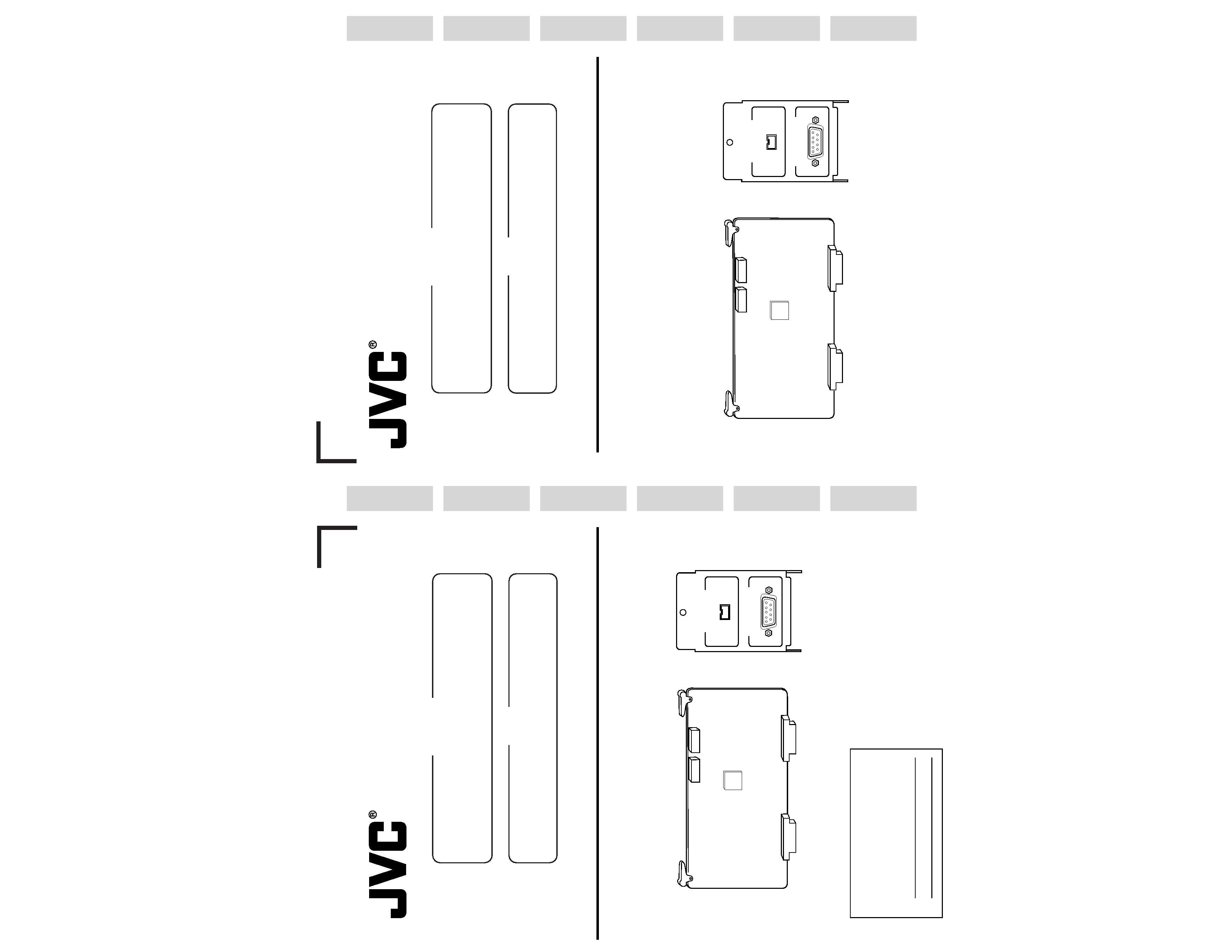
Components
This unit is composed of a circuit board and connector panel.
Circuit board .............. x 1
Connector panel ........ x 1 (with connection wires)
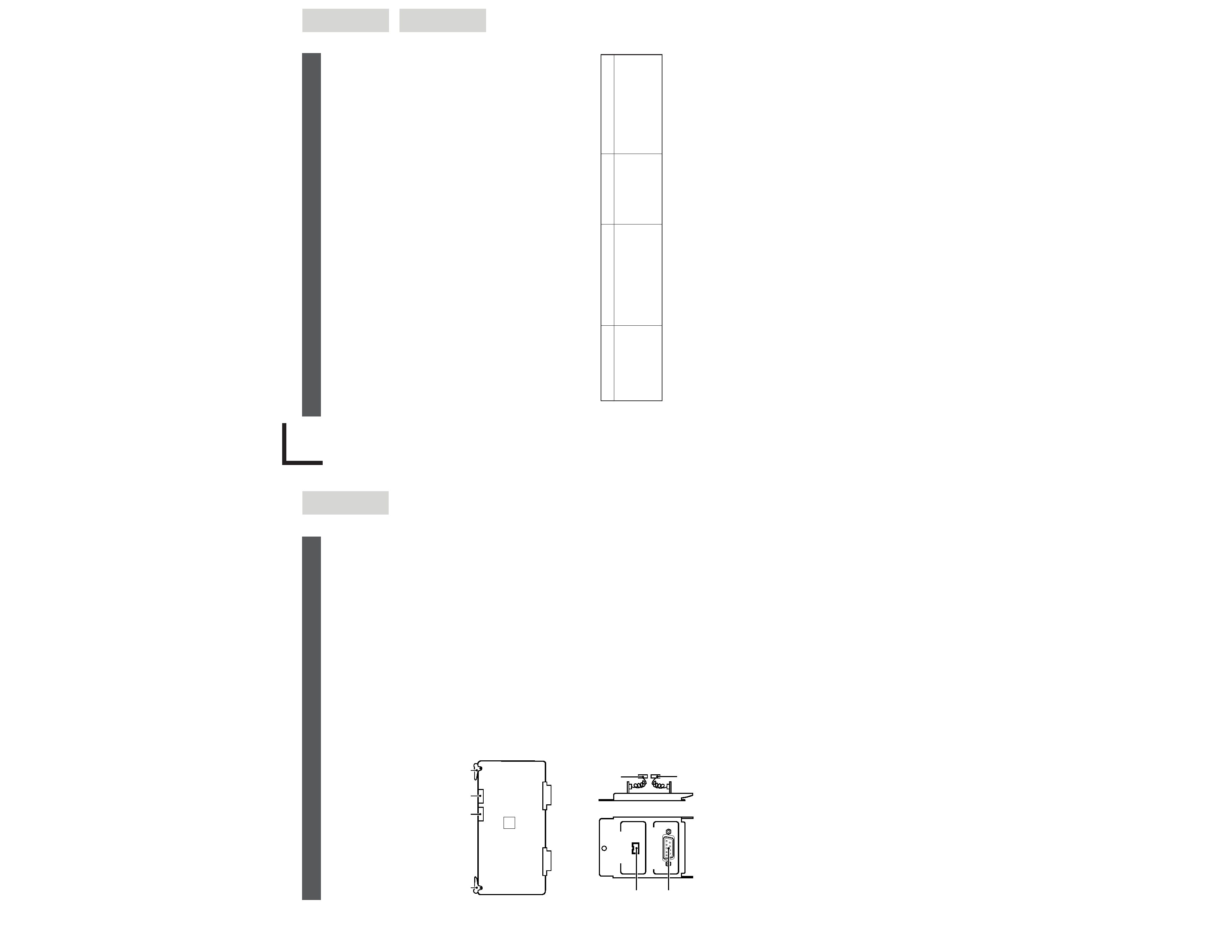
1[CN302] Connect to the 7-pin plug of the connector
panel.
2[CN202] Connect to the 6-pin plug of the connector
panel.
3Ejector Used to eject the board.
Push this part in when inserting the board.
Circuit Board
(DV I/O Board)
Connector Panel
1. Controls, Connectors and Indicators
1
2
3
3
DV I/O
DV IN/OUT
VCR CONTROL
1
2
6-pin plug
7-pin plug
1DV IN/OUT connector
Input and output of IEEE1394 standard digital signals.
In addition to the digital video and digital audio signals,
this connector can also be used to exchange timecode
signals and control signal input from a DV (i.Link)-
compatible PC.
2VCR CONTROL (RS-422 interface) connector
Connect to the REMOTE (9-pin) connector on the D9
main body in order to exchange commands between
the D9 and DV devices through the DV I/O board.
During playback of a D9 device, this connector sends
the timecode signal of the D9 device to the DV device
through the DV I/O board.
Accessories
1. RS-422 cable ..... x 1 (Both millimeter screws and inch screws are provided in the package.)
2. Ferrite core ......... x 1 (To be attached when using headphones)
See page 8 (E-10)
(E-4)
(E-5)
2. System Configuration, Connections
System Configuration and Connection Examples for different Applications
A system for digital editing and/or dubbing can be configured and connected by referring to the
following examples according to the available units and the required function.
Operate the connected units correctly by referring to their instruction manuals.
Cables for connection between units are not provided.
Please purchase the applicable connector cables as required.
DV connection target models
GY-DV500E *1, *3
GY-DV550E
GY-DV700WE *1
BR-DV600E *3
BR-DV600EA
DV nonlinear editor *2
*1. The GY-DV500E and GY-DV700WE models are not capable of DV input recording through
the DV input. Refer to their instruction manuals for details.
*2. For the DV nonlinear editors, please consult your nearest JVC dealer.
*3. Precautions for connection of the GY-DV500E or BR-DV600E
(1) Time codes cannot be dubbed.
(2) When the DV device is switched from the Still mode to the Play mode, audio may be
interrupted momentarily. This is not a malfunction.
(3) Sets having serial numbers other than those shown below cannot be connected to this
unit. For information concerning their upgrade versions, please consult your local JVC-
authorized service agent.
Model Name
Last 5 digits of S/No.
GY-DV500E
xxx14590 and after
xxx54590 and after
xxx30401 and after
GY-DV500EC
xxx10281 and after
xxx50281 and after
Model Name
Last 5 digits of S/No.
GY-DV500ECK
xxx30251 and after
BR-DV600E
xxx11535 and after
xxx51535 and after
BR-DV600EC
xxx10001 and after
xxx50001 and after
E
(U-4)
2. System Configuration, Connections
System Configuration and Connection Examples for different Applications
A system for digital editing and/or dubbing can be configured and connected by referring to the
following examples according to the available units and the required function.
Operate the connected units correctly by referring to their instruction manuals.
Cables for connection between units are not provided.
Please purchase the applicable connector cables as required.
DV connection target models
GY-DV500U *2
GY-DV550U
GY-DV700WU
BR-DV600U *2
BR-DV600UA
DV nonlinear editor *1
*1. For the DV nonlinear editors, please consult your nearest JVC dealer.
*2. Precautions for connection of the GY-DV500U or BR-DV600U
(1) Time codes cannot be dubbed.
(2) When the DV device is switched from the Still mode to the Play mode, audio may be
interrupted momentarily. This is not a malfunction.
(3) Sets having serial numbers other than those shown below cannot be connected to this
unit. For information concerning their upgrade versions, please consult your local JVC-
authorized service agent.
AC IN 120V
50 / 60Hz
VIDEO OUT
REF
VIDEO IN
Y
LINE
R-Y
B-Y
Y/C 358
Y
R-Y
B-Y
Y/C 358
LINE-2
LINE-1
VIDEO
AUDIO
MONITOR OUT
TIME CODE
ON
OFF
75
DIAGNOSTIC
REMOTE (9P)
VIDEO CONTROL
AUD-1
AUD-2
AUD-1
AUD-2
AUDIO IN
AUDIO OUT
LEVEL
- 6dB
+ 4dB
LEVEL
- 6dB
+ 4dB
IN
OUT
DV IN/OUT
VTR CTRL
POWER
ON
OFF
HM
F
S
COUNTER
CTL
TC
UB
REMOTE
LOCAL
9PIN
AUDIO
MONITOR
AUDIO
INPUT
VIDEO
INPUT
DA1
MIX
DA2
DIG
LINE
Y/C
(CPN)
DIG
ANA
REC
PLAY
PAUSE / STILL
REW
STOP
FF
EJECT
SEARCH
PHONES
LEVEL
AUDIO REC LEVEL
DA-2
DA-1
TRACKING
SERVO
VIDEO1
VIDEO2
USER
OTHERS
ON SCREEN
TIME CODE
SYSTEM
STAND BY
TIME CODE
VIDEO CONTROL
MENU
SET
SELECT
METER MODE
FINE
TRACKING
TIME CODE GEN.
SET
HOLD
COUNTER
RESET
SYSTEM
PHASE
SC
PHASE
VIDEO
PHASE
INT
REC PRESET
REGEN
FREE
EXT
CHANNEL
CONDITION
CTL
SERVO
AUTO OFF
DF
EMP
JOG
GEN
VIDEO CASSETTE RECORDER
BR-D80U
OVER
OVER
-15
-16
-17
-18
-19
-20
-21
-22
-23
-24
0
-4
-8
-12
-16
-20
-25
-30
-40
-60
-15
-16
-17
-18
-19
-20
-21
-22
-23
-24
0
-4
-8
-12
-16
-20
-30
-40
-60
-25
STILL
X-1
REV
FWD
X1
DA2/TRACKING
DA1
P.READ
LIGHT
ON
OFF
COUNTER
CTL
TC
UB
RESET
OPERATE/WARNING
MONITOR
SELECT
STATUS
SHUTTER
MENU
FILTER
1 3200k
2 5600k
3 5600k+ND
POWER
NG
GAIN
OUTPUT
WHT.BAL
VTR
ON
OFF
ALARM
MONITOR
S
A
V
E
S
T
B
Y
H
M
L
B
A
R
S
C
A
M
A
U
T
O
K
N
E
E
P
R
S
T
A
B
O
N
O
F
F
CH-1
CH-2
AUDIO
LEVEL
AUTO IRIS
LOLUX
BACK L
NORMAL
SPOT L
STRETCH
NORMAL
COMPRESS
FULL AUTO BLACK
V.IN/A.MONI A.OUT
COUNTER
DV
CTL
TC
UB
CH-1/2
CH-3/4
Y/C
(CPN)
LINE
L
R
MIX
MIX
PHONES
MIC
REMOTE
LOCAL
EJECT
OPERATE
REC LEVEL
CH-2/4
CH-1/3
SHIFT
SET
SELECT
SHIFT
MENU
HOLD
SHIFT
A. DUB
ADVANCE PRESET
REW
STOP
FF
REC
PLAY
PAUSE
ON/OFF
MENU
OVER
OVER
HM
S
F
AUD LOCK
SP
32k
48k
SLAVE
PB
NDF
SERVO RF
DEW
AUTO OFF
HOLD
CH 2/4
CH 1/3
VIDEO CASSETTE RECORDER BR-DV600UA
dB
40 30
20
10
0
LAP
IN
OUT
SERVO
LAP
IN
OUT
SERVO
LAP
RESET
LAP
RESET
TOTAL
RECORDER
EJECT
PLAYER
EJECT
P
AUX
CONTINUE
START
END
V.SPEED
EVENT
RENUMBER
RIPPLE
MAN.TAKE
LEARN
MENU
REC
REW
FF
STOP
STB OFF
SEARCH
PAUSE
/STILL
PLAY
REC
REW
FF
STOP
STB OFF
SEARCH
PAUSE
/STILL
PLAY
ASSEM
VIDEO
AUD-1
AUD-2
SPLIT
TC
SPLIT
CANCEL
LAST
ED
REC
EE
OUT
IN
OUT
IN
ENTRY
PREVIEW
AUTO EDIT
GOTO
REVIEW
SHIFT
ALL STOP
MAX
MIN
MONITOR
MAX
MIN
MONITOR
FWD
REV
STILL
X-1
X1
FWD
REV
STILL
X-1
X1
RECORDER
PLAYER
HOUR
MIN
SEC
FRAME
HOUR
MIN
SEC
FRAME
PR
VITC
LTC
CTL
VITC
LTC
CTL
BUMP
PREROLL
7
5
3
ON
OFF
EVENT No.
V.SPEED
A.SPLIT
DURATION
IN
OUT
IN
OUT
EDITING
CONTROL UNIT
RM -- G820U
+
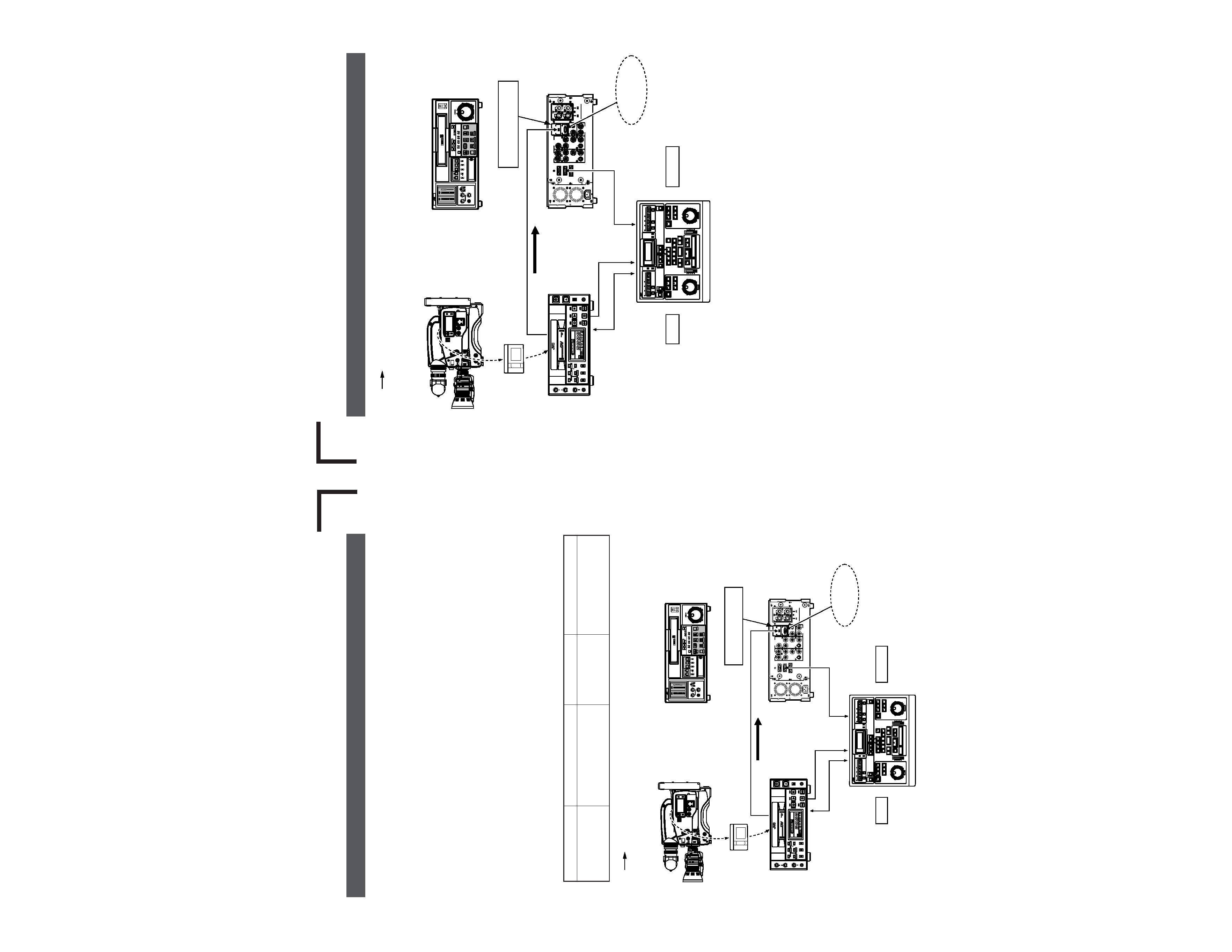
Mini DV
(VIDEO/AUDIO)
DV cable (4P-4P)
Mini DV
tape
DV recorder
BR-DV600UA
Player
Editing control unit RM-G820U
D9 editing recorder BR-D80U
DV camcorder GY-DV500U
Front panel
Rear panel
DV connector
DV connector
SA-DV60U
VCR CONTROL
not connected
REMOTE(9P)
REMOTE(9P)
VIDEO OUT
SYNC
IN
9P-9P remote cable
9P-9P remote cable
Recorder
· For data bump, select the recorder
device and use its Learning function.
· The pre-roll time should be set to
more than 5 seconds.
Model Name
Last 5 digits of S/No.
GY-DV500U
xxx16552 and after
xxx56552 and after
xxx31501 and after
Model Name
Last 5 digits of S/No.
BR-DV600U
xxx12040 and after
xxx52040 and after
(1) DV
D9 linear editing system
The editing precision of the player device of the system described below is +1(
) frame.
+1
0
(E-6)
AC IN 120V
50 / 60Hz
VIDEO OUT
REF
VIDEO IN
Y
LINE
R-Y
B-Y
Y/C 358
Y
R-Y
B-Y
Y/C 358
LINE-2
LINE-1
VIDEO
AUDIO
MONITOR OUT
TIME CODE
ON
OFF
75
DIAGNOSTIC
REMOTE (9P)
VIDEO CONTROL
AUD-1
AUD-2
AUD-1
AUD-2
AUDIO IN
AUDIO OUT
LEVEL
- 6dB
+ 4dB
LEVEL
- 6dB
+ 4dB
IN
OUT
DV IN/OUT
VTR CTRL
POWER
ON
OFF
HM
F
S
COUNTER
CTL
TC
UB
REMOTE
LOCAL
9PIN
AUDIO
MONITOR
AUDIO
INPUT
VIDEO
INPUT
DA1
MIX
DA2
DIG
LINE
Y/C
(CPN)
DIG
ANA
REC
PLAY
PAUSE / STILL
REW
STOP
FF
EJECT
SEARCH
PHONES
LEVEL
AUDIO REC LEVEL
DA-2
DA-1
TRACKING
SERVO
VIDEO1
VIDEO2
USER
OTHERS
ON SCREEN
TIME CODE
SYSTEM
STAND BY
TIME CODE
VIDEO CONTROL
MENU
SET
SELECT
METER MODE
FINE
TRACKING
TIME CODE GEN.
SET
HOLD
COUNTER
RESET
SYSTEM
PHASE
SC
PHASE
VIDEO
PHASE
INT
REC PRESET
REGEN
FREE
EXT
CHANNEL
CONDITION
CTL
SERVO
AUTO OFF
DF
EMP
JOG
GEN
VIDEO CASSETTE RECORDER
BR-D80U
OVER
OVER
-15
-16
-17
-18
-19
-20
-21
-22
-23
-24
0
-4
-8
-12
-16
-20
-25
-30
-40
-60
-15
-16
-17
-18
-19
-20
-21
-22
-23
-24
0
-4
-8
-12
-16
-20
-30
-40
-60
-25
STILL
X-1
REV
FWD
X1
DA2/TRACKING
DA1
P.READ
LIGHT
ON
OFF
COUNTER
CTL
TC
UB
RESET
OPERATE/WARNING
MONITOR
SELECT
STATUS
SHUTTER
MENU
FILTER
1 3200k
2 5600k
3 5600k+ND
POWER
NG
GAIN
OUTPUT
WHT.BAL
VTR
ON
OFF
ALARM
MONITOR
S
A
V
E
S
T
B
Y
H
M
L
B
A
R
S
C
A
M
A
U
T
O
K
N
E
E
P
R
S
T
A
B
O
N
O
F
F
CH-1
CH-2
AUDIO
LEVEL
AUTO IRIS
LOLUX
BACK L
NORMAL
SPOT L
STRETCH
NORMAL
COMPRESS
FULL AUTO BLACK
V.IN/A.MONI A.OUT
COUNTER
DV
CTL
TC
UB
CH-1/2
CH-3/4
Y/C
(CPN)
LINE
L
R
MIX
MIX
PHONES
MIC
REMOTE
LOCAL
EJECT
OPERATE
REC LEVEL
CH-2/4
CH-1/3
SHIFT
SET
SELECT
SHIFT
MENU
HOLD
SHIFT
A. DUB
ADVANCE PRESET
REW
STOP
FF
REC
PLAY
PAUSE
ON/OFF
MENU
OVER
OVER
HM
S
F
AUD LOCK
SP
32k
48k
SLAVE
PB
NDF
SERVO RF
DEW
AUTO OFF
HOLD
CH 2/4
CH 1/3
VIDEO CASSETTE RECORDER BR-DV600UA
dB
40 30
20
10
0
LAP
IN
OUT
SERVO
LAP
IN
OUT
SERVO
LAP
RESET
LAP
RESET
TOTAL
RECORDER
EJECT
PLAYER
EJECT
P
AUX
CONTINUE
START
END
V.SPEED
EVENT
RENUMBER
RIPPLE
MAN.TAKE
LEARN
MENU
REC
REW
FF
STOP
STB OFF
SEARCH
PAUSE
/STILL
PLAY
REC
REW
FF
STOP
STB OFF
SEARCH
PAUSE
/STILL
PLAY
ASSEM
VIDEO
AUD-1
AUD-2
SPLIT
TC
SPLIT
CANCEL
LAST
ED
REC
EE
OUT
IN
OUT
IN
ENTRY
PREVIEW
AUTO EDIT
GOTO
REVIEW
SHIFT
ALL STOP
MAX
MIN
MONITOR
MAX
MIN
MONITOR
FWD
REV
STILL
X-1
X1
FWD
REV
STILL
X-1
X1
RECORDER
PLAYER
HOUR
MIN
SEC
FRAME
HOUR
MIN
SEC
FRAME
PR
VITC
LTC
CTL
VITC
LTC
CTL
BUMP
PREROLL
7
5
3
ON
OFF
EVENT No.
V.SPEED
A.SPLIT
DURATION
IN
OUT
IN
OUT
EDITING
CONTROL UNIT
RM -- G820U
+
Mini DV
(VIDEO/AUDIO)
DV cable (4P-4P)
Mini DV
tape
DV recorder
BR-DV600EA
Player
Editing control unit RM-G820E
D9 editing recorder BR-D80E
DV camcorder GY-DV500E
(1) DV
D9 linear editing system
Front panel
Rear panel
DV connector
DV connector
SA-DV60E
VCR CONTROL
not connected
REMOTE(9P)
REMOTE(9P)
VIDEO OUT
SYNC
IN
9P-9P remote cable
9P-9P remote cable
Recorder
· For data bump, select the recorder
device and use its Learning function.
· The pre-roll time should be set to
more than 5 seconds.
The editing precision of the player device of the system described below is +1
frame.
+1
0
( )
2. System Configuration, Connections (continued)
E
U