For Customer Use:
Enter below the Model No. and Serial
No. which are located either on the rear,
bottom or side of the cabinet. Retain this
information for future reference.
Model No.
Serial No.
LVT0650-001A
[J]
INSTRUCTIONS
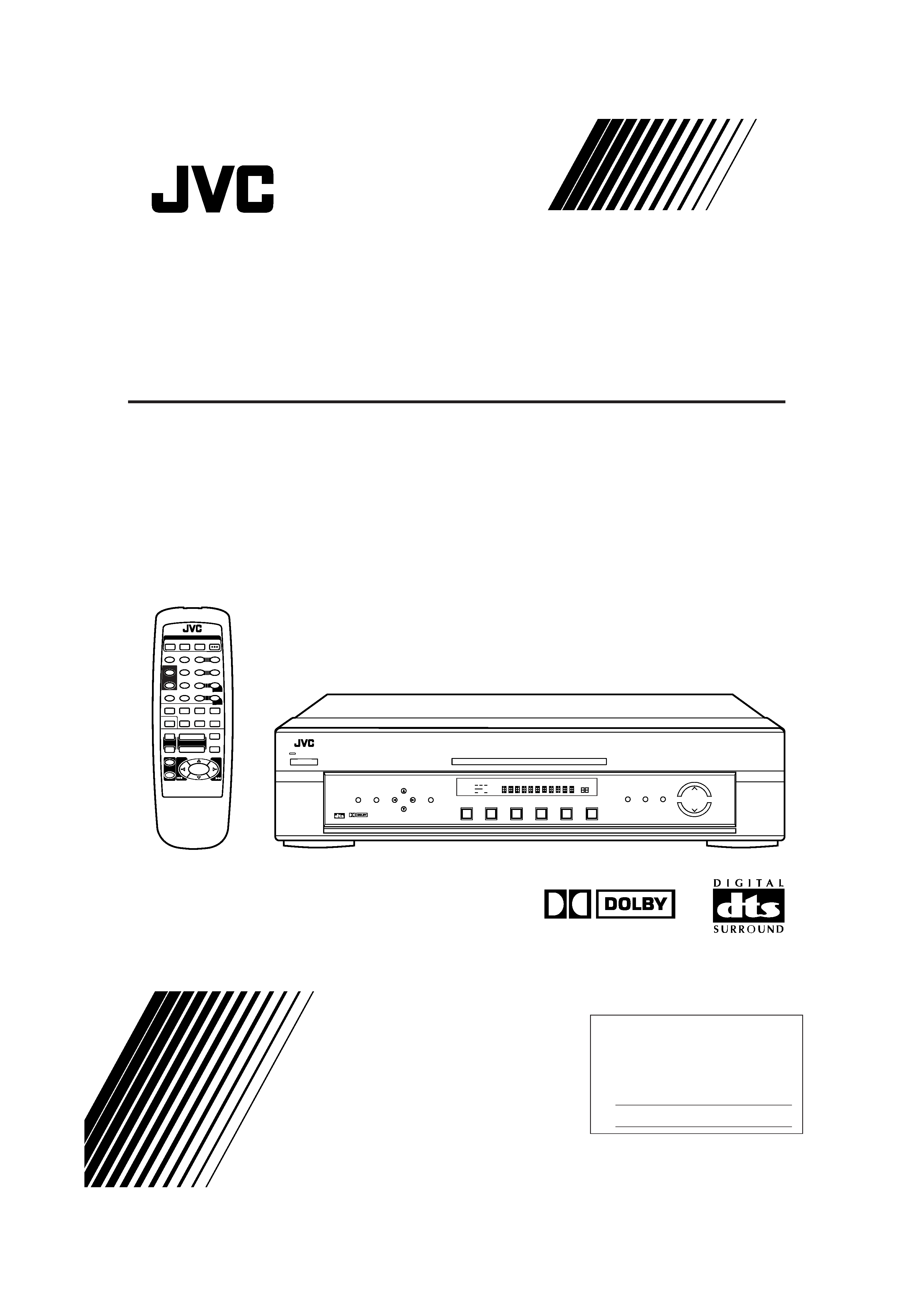
RX-E100SL
HOME THEATER RECEIVER
DIGITAL
DVD
TV
VCR
CD
FM
AM
RX-E100
HOME THEATER RECEIVER
TV DILECT
DVD
MEMORY
CONTROL
ADJUST
SETTING
STANDBY
DIGITAL
DIGITAL
SURROUND
INPUT
ANALOG/DIGITAL
INPUT ATT
MASTER VOLUME
SURROUND
ON/OFF
DSP
MODE
ANALOG
PRO LOGIC
SUBWFR LFE
SLEEP
ST
TUNED
MUTING
MHZ
KHZ
VOL
AUTO
DGTL AUTO
INPUT ATT
DSP
LC
R
LS
S
RS
LPCM
DOLBY D
DTS
POWER
1
1
REMOTE CONTROL
SURROUND
DSP MODE
SOUND
1
5
SUBWOOFER +
TEST
SLEEP
6
5
4
EFFECT
CENTER +
5
9
8
REAR·L +
BASS
BOOST
5
REAR·R +
MENU
5
CD
AM
MUTING
TV/VIDEO
TV
VCR
FM
TV VOL
TV/VCR
CH
DVD
+
+
VOLUME
POWER
8
7
RM-SRXE100J
HOME THEATER RECEIVER
3
2
INPUT A/D
ENTER
+10
0
10
+
+
7
£
TV
VCR
AUDIO
DVD
RX-E100SL[J]_COVER_f
01.3.7, 2:43 PM
1
Warnings, Cautions and Others
CAUTION:
TO REDUCE THE RISK OF ELECTRIC SHOCK.
DO NOT REMOVE COVER (OR BACK)
NO USER SERVICEABLE PARTS INSIDE.
REFER SERVICING TO QUALIFIED SERVICE PERSONNEL.
RISK OF ELECTRIC SHOCK
DO NOT OPEN
The lightning flash with arrowhead symbol,
within an equilateral triangle is intended to
alert the user to the presence of uninsulated
"dangerous voltage" within the product's
enclosure
that
may
be
of
sufficient
magnitude to constitute a risk of electric
shock to persons.
The exclamation point within an equilateral
triangle is intended to alert the user to the
presence
of
important
operating
and
maintenance (servicing) instructions in the
literature accompanying the appliance.
CAUTION
CAUTION
To reduce the risk of electrical shocks, fire, etc.:
1.
Do not remove screws, covers or cabinet.
2.
Do not expose this appliance to rain or moisture.
ATTENTION
Afin d'éviter tout risque d'électrocution, d'incendie, etc.:
1.
Ne pas enlever les vis ni les panneaux et ne pas ouvrir le
coffret de l'appareil.
2.
Ne pas exposer l'appareil à la pluie ni à l'humidité.
WARNING: TO REDUCE THE RISK OF FIRE
OR ELECTRIC SHOCK, DO NOT EXPOSE
THIS APPLIANCE TO RAIN OR MOISTURE.
Caution POWER switch!
Disconnect the mains plug to shut the power off completely. The
POWER switch in any position does not disconnect the mains
line. The power can be remote controlled.
Attention Commutateur POWER!
Déconnecter la fiche de secteur pour couper complètement le
courant. Le commutateur POWER ne coupe jamais
complètement la ligne de secteur, quelle que soit sa position. Le
courant peut être télécommandé.
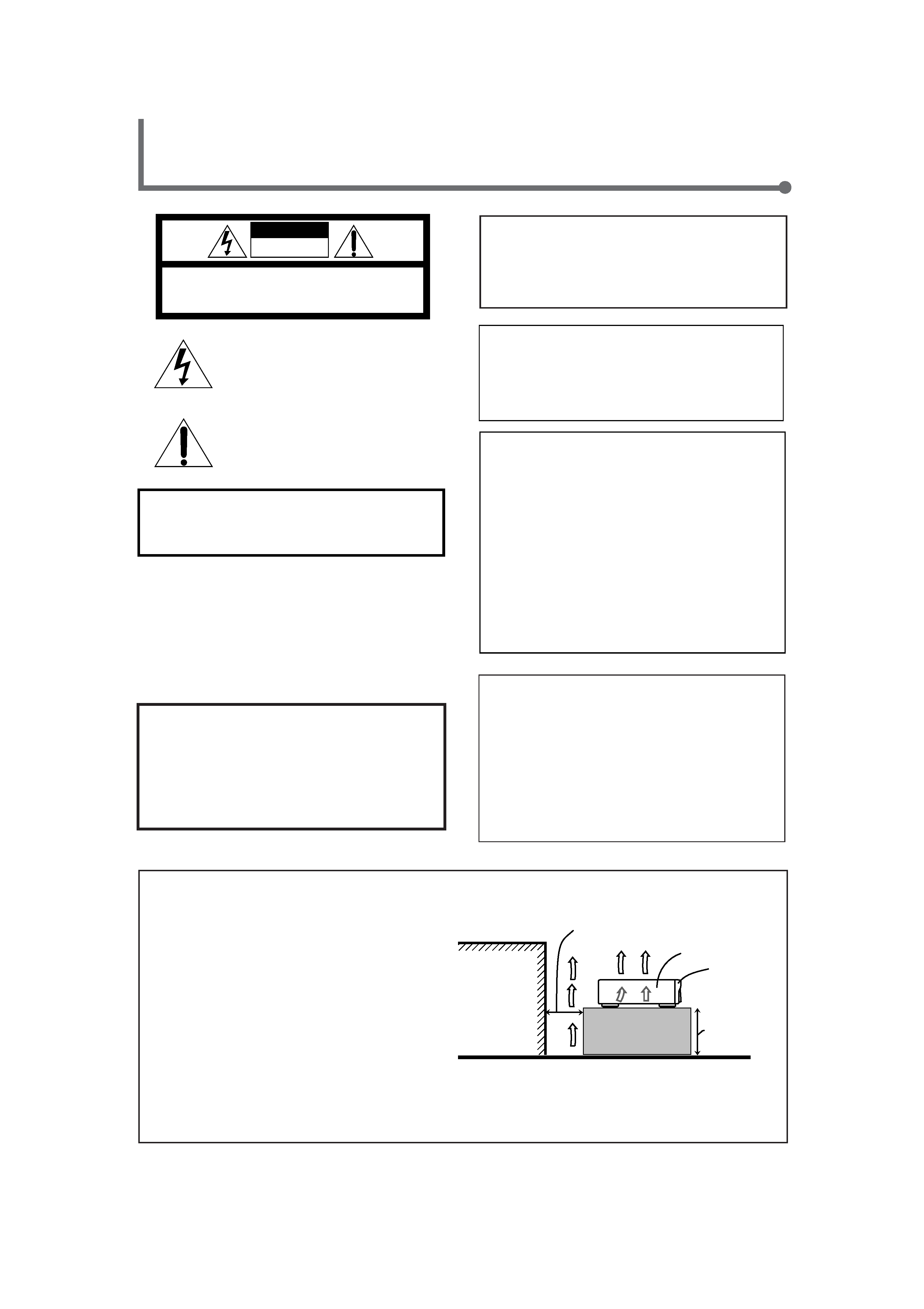
Caution: Proper Ventilation
To avoid risk of electric shock and fire and to protect from damage.
Locate the apparatus as follows:
Front:
No obstructions open spacing.
Sides:
No obstructions in 10 cm from the sides.
Top:
No obstructions in 10 cm from the top.
Back:
No obstructions in 15 cm from the back
Bottom:
No obstructions, place on the level surface.
In addition, maintain the best possible air circulation as illustrated.
Attention: Ventilation Correcte
Pour éviter les chocs électriques, l'incendie et tout autre dégât.
Disposer l'appareil en tenant compte des impératifs suivants
Avant:
Rien ne doit gêner le dégagement
Flancs:
Laisser 10 cm de dégagement latéral
Dessus:
Laisser 10 cm de dégagement supérieur
Arrière:
Laisser 15 cm de dégagement arrière
Dessous:
Rien ne doit obstruer par dessous; poser l'appareil sur une
surface plate.
Veiller également à ce que l'air circule le mieux possible comme illustré.
Front
Avant
RX-E100SL
Spacing 15 cm or more
Dégagement de 15 cm ou plus
Wall or obstructions
Mur, ou obstruction
Floor
Plancher
Stand height 15
cm or more
Hauteur du socle:
15 cm ou plus
For U.S.A.
This equipment has been tested and found to comply with the limits
for a Class B digital device, pursuant to part 15 of the FCC Rules.
These limits are designed to provide reasonable protection against
harmful interference in a residential installation.
This equipment generates, uses and can radiate radio frequency
energy and, if not installed and used in accordance with the
instructions,
may
cause
harmful
interference
to
radio
communications. However, there is no guarantee that interference
will not occur in a particular installation. If this equipment does cause
harmful interference to radio or television reception, which can be
determined by turning the equipment off and on, the user is
encouraged to try to correct the interference by one or more of the
following measures:
Reorient or relocate the receiving antenna.
Increase the separation between the equipment and receiver.
Connect the equipment into an outlet on a circuit different from that
to which the receiver is connected.
Consult the dealer or an experienced radio/TV technician for help.
For Canada/pour Le Canada
THIS DIGITAL APPARATUS DOES NOT EXCEED THE CLASS
B LIMITS FOR RADIO NOISE EMISSIONS FROM DIGITAL
APPARATUS AS SET OUT IN THE INTERFERENCE-CAUSING
EQUIPMENT STANDARD ENTITLED "DIGITAL APPARATUS,"
ICES-003 OF THE DEPARTMENT OF COMMUNICATIONS.
CET APPAREIL NUMERIQUE RESPECTE LES LIMITES DE
BRUITS RADIOELECTRIQUES APPLICABLES AUX
APPAREILS NUMERIQUES DE CLASSE B PRESCRITES
DANS LA NORME SUR LE MATERIEL BROUILLEUR;
"APPAREILS NUMERIQUES", NMB-003 EDICTEE PAR LE
MINISTRE DES COMMUNICATIONS.
For Canada/pour le Canada
CAUTION: TO PREVENT ELECTRIC SHOCK, MATCH WIDE
BLADE OF PLUG TO WIDE SLOT, FULLY INSERT
ATTENTION: POUR EVITER LES CHOCS ELECTRIQUES,
INTRODUIRE LA LAME LA PLUS LARGE DE LA FICHE DANS LA
BORNE CORRESPONDANTE DE LA PRISE ET POUSSER
JUSQUAU FOND
Note to CATV system installer:
This reminder is provided to call the CATV system installer's
attention to Section 820-40 of the NEC which provides
guidelines for proper grounding and, in particular, specifies that
the cable ground shall be connected to the grounding system
of the building, as close to the point of cable entry as practical.
RX-E100SL[J]_Safety_f
01.3.7, 2:46 PM
1
1
Table of Contents
Getting Started ........................................... 2
Before Installation ...................................................................... 2
Checking the Supplied Accessories ........................................... 2
Putting Batteries in the Remote Control .................................... 2
Connecting the FM and AM Antennas ....................................... 3
Connecting the Speakers ............................................................ 4
Connecting Audio/Video Components ....................................... 6
Connecting the Power Cord ....................................................... 6
Basic Operations ......................................... 8
1 Turn On the Power ................................................................. 8
2 Select the Source to Play ....................................................... 8
3 Adjust the Volume .................................................................. 8
Turning Off the Power with the Timer ....................................... 9
Basic Settings ........................................... 10
Setting the Digital Input Terminals .......................................... 10
Selecting the Analog or Digital Input Mode ............................ 11
Setting the Subwoofer Information .......................................... 12
Setting the Speakers for DSP Modes ....................................... 12
Setting Auto Surround .............................................................. 16
Sound Adjustments .................................... 17
Attenuating the Input Signal .................................................... 17
Adjusting the Front Speaker Output Balance ........................... 17
Reinforcing the Bass ................................................................ 18
Adjusting the Tone ................................................................... 19
Adjusting the Subwoofer Output Level .................................... 19
Tuner Operations ....................................... 20
Tuning in Stations Manually .................................................... 20
Using Preset Tuning ................................................................. 20
Selecting the FM Reception Mode ........................................... 21
Creating Realistic Sound Fields ................... 22
About Relations between Speaker Layout and DSP Modes ....... 24
Using Surround Modes (Remote Control) ............................... 25
Using Theater Surround (Remote Control) .............................. 26
Using DAP Modes (Remote Control) ...................................... 28
Using Surround Modes (Front Panel) ...................................... 29
Using Theater Surround (Front Panel) ..................................... 30
Using DAP Modes (Front Panel) ............................................. 31
Mastering Remote Operations .................... 32
Parts Identification .................................... 34
Troubleshooting ......................................... 35
Specifications ............................................ 36
Memorandum ............................................ 37
W
arnings,
Cautions
and
Others/T
able
of
Contents
Remote
ONLY
Remote
NOT
This mark indicates that only the remote control
CANNOT be used for the operation explained.
This mark indicates that the remote control CAN
ONLY be used for the operation explained.
EN01-07.RX-E100SL[J]_f
01.3.7, 2:47 PM
1
2
Getting Started
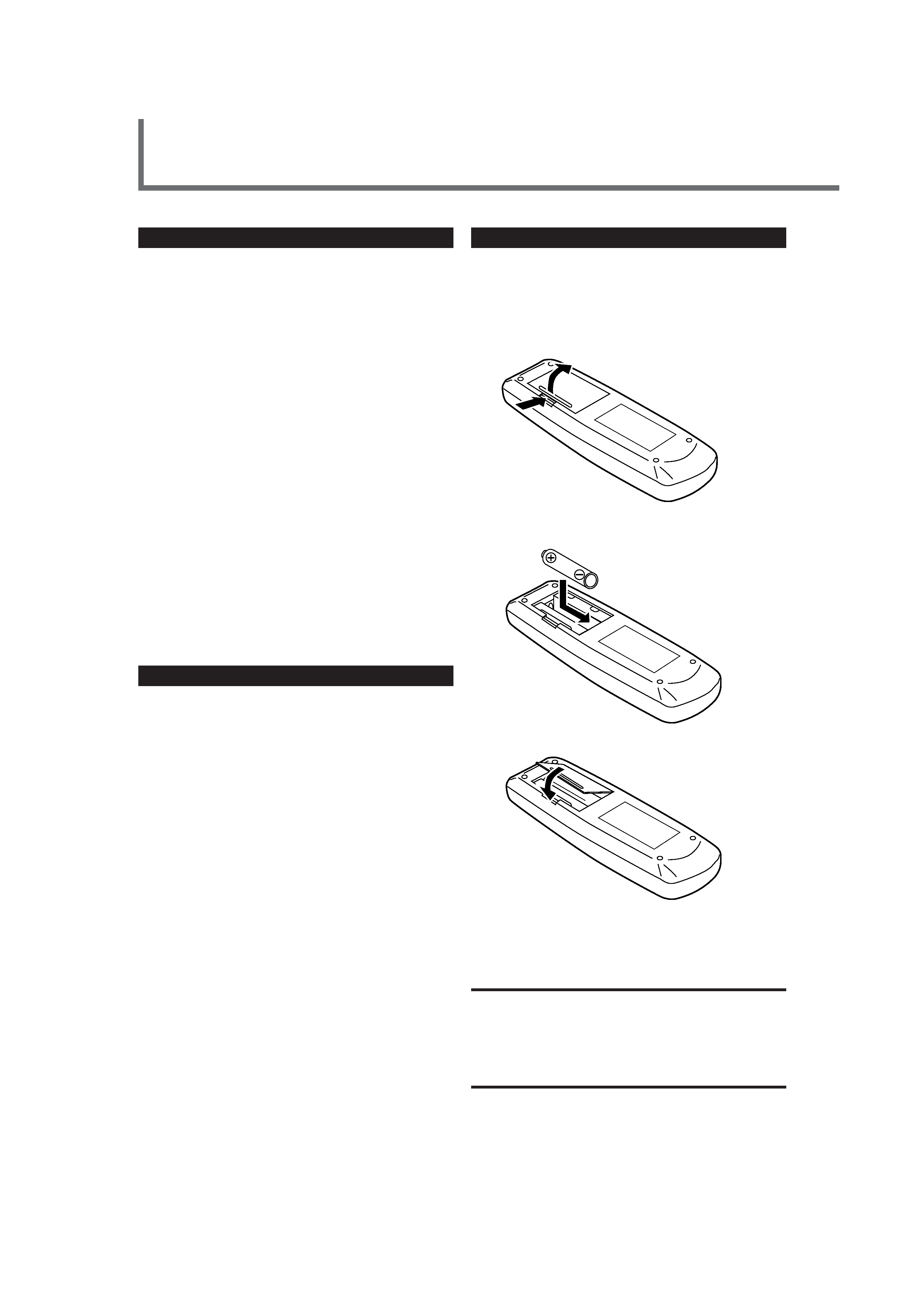
Putting Batteries in the Remote Control
Before using the remote control, put two supplied batteries first.
· When using the remote control, aim the remote control directly at
the remote sensor on the receiver.
1. On the back of the remote control, remove the
battery cover.
2. Insert batteries. Make sure to match the polarity:
(+) to (+) and () to ().
3. Replace the cover.
If the range or effectiveness of the remote control decreases, replace
the batteries. Use two R6P(SUM-3)/AA(15F) type dry-cell batteries.
CAUTION:
Follow these precautions to avoid leaking or cracking cells:
· Place batteries in the remote control so they match the polarity: (+)
to (+) and () to ().
· Use the correct type of batteries. Batteries that look similar may
differ in voltage.
· Always replace both batteries at the same time.
· Do not expose batteries to heat or flame.
Before Installation
General Precautions
· DO NOT insert any metal object into the receiver.
· DO NOT disassemble the receiver or remove screws, covers, or
cabinet.
· DO NOT expose the receiver to rain or moisture.
Locations
· Install the receiver in a location that is level and protected from
moisture.
· The temperature around the receiver must be between 23°F and
95°F (5°C and 35°C).
· Make sure there is good ventilation around the receiver. Poor
ventilation could cause overheating and damage the receiver.
Handling the receiver
· DO NOT touch the power cord with wet hands.
· DO NOT pull on the power cord to unplug the cord. When
unplugging the cord, always grasp the plug so as not to damage
the cord.
· Keep the power cord away from the connecting cords and the
antenna. The power cord may cause noise or screen interference. It
is recommended to use a coaxial cable for antenna connection,
since it is well-shielded against interference.
· When a power failure occurs, or when you unplug the power cord,
the preset settings such as preset FM/AM channels and sound
adjustments may be erased in a few days.
Checking the Supplied Accessories
Check to be sure you have all of the following supplied accessories.
The number in the parentheses indicates the quantity of the pieces
supplied.
· Remote Control (1)
· Batteries (2)
· AM Loop Antenna (1)
· FM Antenna (1)
If anything is missing, contact your dealer immediately.
1
2
EN01-07.RX-E100SL[J]_f
01.3.7, 2:47 PM
2
3
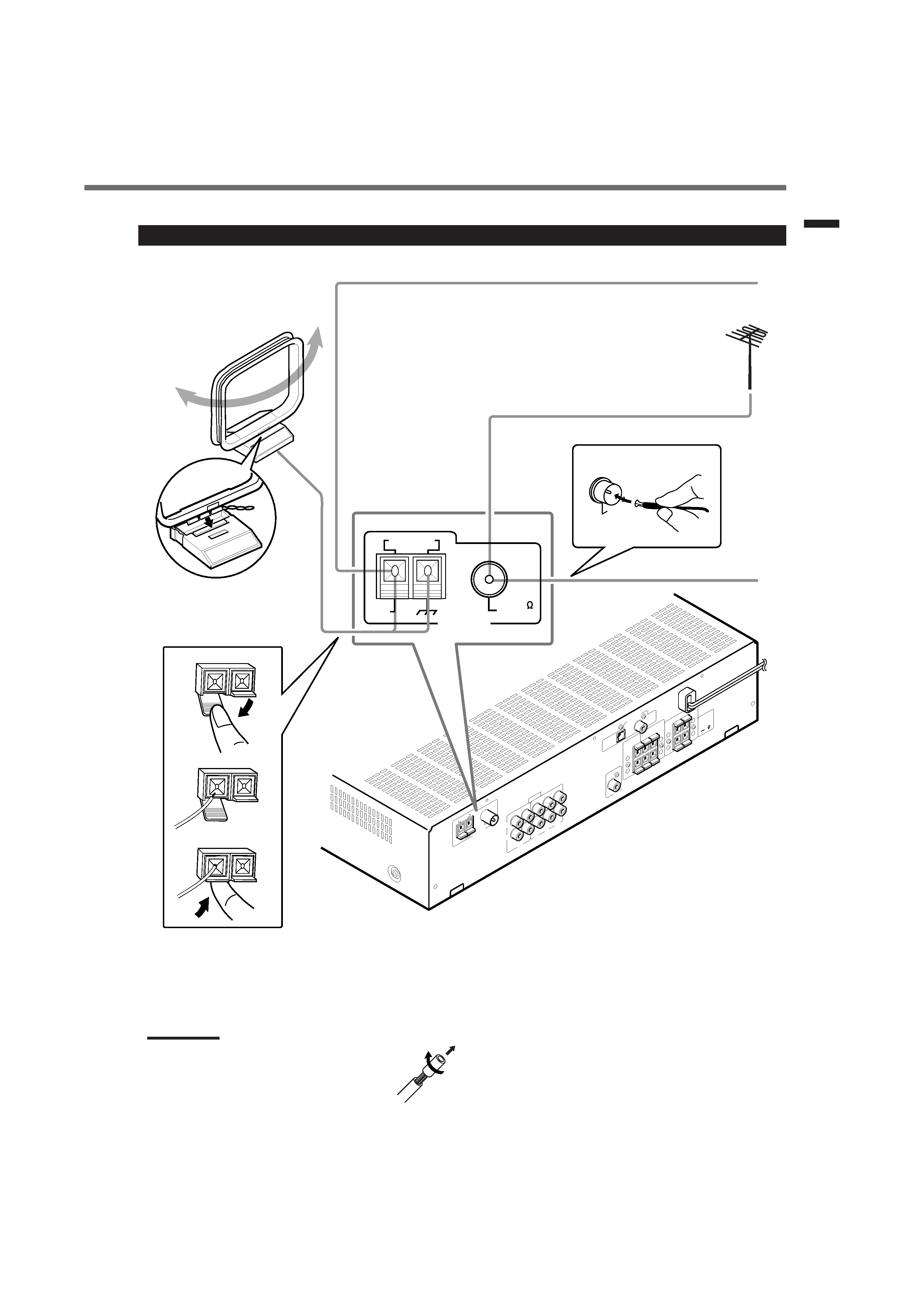
Connecting the FM and AM Antennas
FM Antenna (supplied)
If FM reception is poor, connect
outdoor FM antenna (not supplied).
AM antenna connection
Connect the AM loop antenna supplied to the AM LOOP
terminals.
Turn the loop until you have the best reception.
· If reception is poor, connect an outdoor single vinyl-covered
wire to the AM EXT terminal. (Keep the AM loop antenna
connected.)
FM antenna connection
Connect the FM antenna supplied to the FM 75
COAXIAL
terminal as temporary measure.
Extend the supplied FM antenna horizontally.
· If reception is poor, connect an outdoor antenna. Before
attaching a 75
coaxial cable (with a standard type connector),
disconnect the supplied FM antenna.
Notes:
· If the AM loop antenna wire is covered with vinyl,
remove the vinyl while twisting it as shown to the
right.
· Make sure the antenna conductors do not touch any
other terminals, connecting cords and power cord.
This could cause poor reception.
Getting
Started
Snap the tabs on the loop into
the slots of the base to
assemble the AM loop antenna.
If AM reception is poor, connect single vinyl-covered wire (not supplied).
AM Loop Antenna
(supplied)
FM
75
COAXIAL
CAUTION
:
SPEAKER
IMPEDANCE
8
16
+
+
+
+
AM
LO
OP
AM
EXT
ANTENNA
AUDIO
RIGHT
LEFT
OUT
(REC)
IN
(PLA
Y)
VCR
CD
TV
DVD
SUBWOOFER
OUT
DIGIT
AL
2
(TV
)
DIGIT
AL
1
(D
VD
)
DIGIT
AL
IN
CENTER
SPEAKER
REAR
SPEAKERS
RIGHT
LEFT
FRONT
SPEAKERS
RIGHT
LEFT
FM
75
CO
AX
IAL
ANTENNA
AM LOOP
FM 75
COAXIAL
AM
EXT
B
1
2
3
FM
75
CO
AXIAL
EN01-07.RX-E100SL[J]_f
01.3.7, 2:47 PM
3