SERVICE MANUAL
AUDIO/VIDEO CONTROL RECEIVER
No.20951
May 2001
COPYRIGHT
2001 VICTOR COMPANY OF JAPAN, LTD.
RX-E100RSL
RX-E100RSL/RX-E100RSB
E
EN
Continental Europe
Northern Europe
Area Suffix
Contents
Safety precautions --------------------------------------------------------1- 2
Disassembly method -----------------------------------------------------1- 3
Adjustment method -------------------------------------------------------1- 8
Description of major ICs -------------------------------------------------1- 9
15
RX-E100RSB
RX-E100RSL
RX-E100RSB
Each difference points
Source indication lens colour
SILVER
SILVER BLACK
MODEL
B
E
EN
U.K.
Continental Europe
Northern Europe
RX-E100RSL
RX-E100RSB
RM-SRXE100R REMOTE CONTROL
HOME CINEMA CONTROL CENTER
CONTROL
CHANNEL
VOLUME
TV VOL
TUNING
STOP
PAUSE
FF/
/REW
DIMMER
TV/VIDEO
VCR
MUTING
REC
PLAY
DOWN
UP
DVD
SLEEP
TV DIRECT
DVD
STB
VCR
TV
ANALOG/DIGITAL
TAPE
FM
SOUND
BASS+
CENTER
TEST
BASS
REAR-L
BASS BOOST TREBLE+
REAR-R
EFFECT
TREBLE
SUBWOOFER
RETURN
FM MODE
EON
ENTER
DISPLAY MODE
RDS
MODE
ON/OFF
AM
12
3
45
6
78
9
10
0
+10
100+
DVD
MENU
VCR
TV
STB
INPUT
DSP
SURROUND
EON SELECT
PTY SEARCH
PTY
(
PTY
9
AUDIO
DVD MENU
DVD
STB
VCR
TV
TAPE
FM/AM
RX-E100R
DVD
STB
VCR
TV
TAPE
FM/AM
HOME CINEMA CONTROL CENTER
TV DILECT
DVD
MEMORY
CONTROL
ADJUST
SETTING
STANDBY
DIGITAL
DIGITAL
SURROUND
INPUT
ANALOG/DIGITAL
INPUT ATT
MASTER VOLUME
SURROUND
ON/OFF
DSP
MODE
ANALOG
PRO LOGIC
SUBWFR LFE
SLEEP
ST
TUNED
MUTING
MHZ
KHZ
VOL
AUTO
DGTL AUTO
INPUT ATT
DSP
LC
R
LS
S
RS
LPCM
DOLBY D
DTS

RX-E100RSL/RX-E100RSB
1-2
1. This design of this product contains special hardware and many circuits and components specially for safety
purposes. For continued protection, no changes should be made to the original design unless authorized in
writing by the manufacturer. Replacement parts must be identical to those used in the original circuits. Services
should be performed by qualified personnel only.
2. Alterations of the design or circuitry of the product should not be made. Any design alterations of the product
should not be made. Any design alterations or additions will void the manufacturer`s warranty and will further
relieve the manufacture of responsibility for personal injury or property damage resulting therefrom.
3. Many electrical and mechanical parts in the products have special safety-related characteristics. These
characteristics are often not evident from visual inspection nor can the protection afforded by them necessarily
be obtained by using replacement components rated for higher voltage, wattage, etc. Replacement parts which
have these special safety characteristics are identified in the Parts List of Service Manual. Electrical
components having such features are identified by shading on the schematics and by (
) on the Parts List in
the Service Manual. The use of a substitute replacement which does not have the same safety characteristics
as the recommended replacement parts shown in the Parts List of Service Manual may create shock, fire, or
other hazards.
4. The leads in the products are routed and dressed with ties, clamps, tubings, barriers and the like to be
separated from live parts, high temperature parts, moving parts and/or sharp edges for the prevention of
electric shock and fire hazard. When service is required, the original lead routing and dress should be
observed, and it should be confirmed that they have been returned to normal, after re-assembling.
5. Leakage currnet check (Electrical shock hazard testing)
After re-assembling the product, always perform an isolation check on the exposed metal parts of the product
(antenna terminals, knobs, metal cabinet, screw heads, headphone jack, control shafts, etc.) to be sure the
product is safe to operate without danger of electrical shock.
Do not use a line isolation transformer during this check.
Plug the AC line cord directly into the AC outlet. Using a "Leakage Current Tester", measure the leakage
current from each exposed metal parts of the cabinet, particularly any exposed metal part having a return
path to the chassis, to a known good earth ground. Any leakage current must not exceed 0.5mA AC (r.m.s.).
Alternate check method
Plug the AC line cord directly into the AC outlet. Use an AC voltmeter having, 1,000 ohms per volt or more
sensitivity in the following manner. Connect a 1,500
10W resistor paralleled by a 0.15 F AC-type capacitor
between an exposed metal part and a known good earth ground.
Measure the AC voltage across the resistor with the AC
voltmeter.
Move the resistor connection to eachexposed metal part,
particularly any exposed metal part having a return path to
the chassis, and meausre the AC voltage across the resistor.
Now, reverse the plug in the AC outlet and repeat each
measurement. voltage measured Any must not exceed 0.75 V
AC (r.m.s.). This corresponds to 0.5 mA AC (r.m.s.).
1. This equipment has been designed and manufactured to meet international safety standards.
2. It is the legal responsibility of the repairer to ensure that these safety standards are maintained.
3. Repairs must be made in accordance with the relevant safety standards.
4. It is essential that safety critical components are replaced by approved parts.
5. If mains voltage selector is provided, check setting for local voltage.
Good earth ground
Place this
probe on
each exposed
metal part.
AC VOLTMETER
(Having 1000
ohms/volts,
or more sensitivity)
1500
10W
0.15 F AC TYPE
!
Burrs formed during molding may
be left over on some parts of the
chassis. Therefore, pay attention to
such burrs in the case of
preforming repair of this system.
In regard with component parts appearing on the silk-screen printed side (parts side) of the PWB diagrams, the
parts that are printed over with black such as the resistor (
), diode (
) and ICP (
) or identified by the " "
mark nearby are critical for safety.
When replacing them, be sure to use the parts of the same type and rating as specified by the manufacturer.
(Except the JC version)
RX-E100RSL/RX-E100RSB
1-3
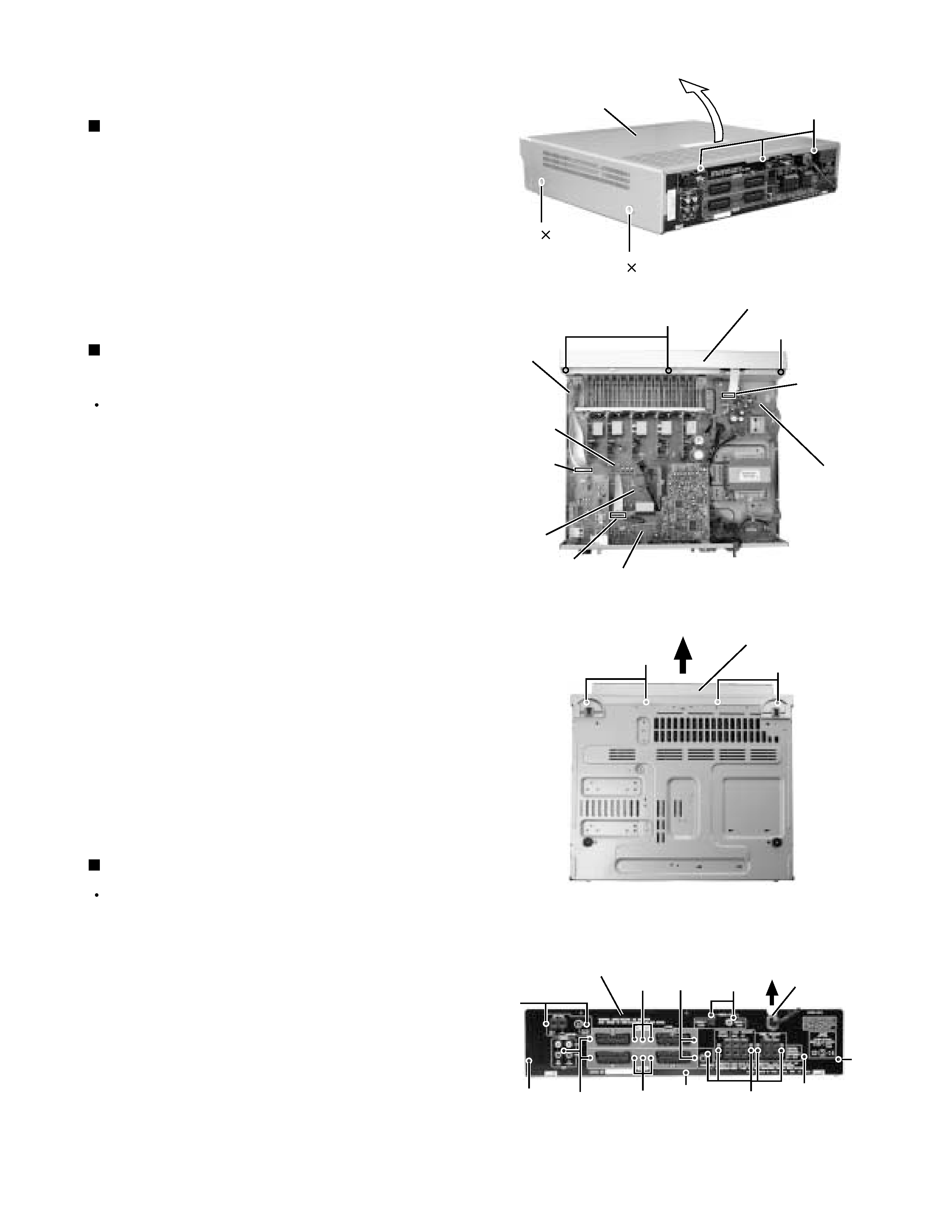
Remove the four screws A attaching the top cover
on both sides of the body.
Remove the three screws B on the back of the body.
Remove the top cover from behind in the direction of
the arrow while pulling both sides outward.
1.
2.
3.
Disassembly method
Removing the top cover (See Fig.1)
Prior to performing the following procedure, remove
the top cover.
Remove the power cord stopper from the rear panel
by moving it in the direction of the arrow.
Remove the twenty one screws E
attaching the
each boards to the rear panel on the back of the
body.
Remove the four screws F attaching the rear panel
on the back of the body.
1.
2.
3.
Removing the rear panel (See Fig.4)
Prior to performing the following procedure, remove
the top cover.
Disconnect the card wire from connector CN411 on
the audio board, CN412 on the input board and
CN204 on the power supply board in the front panel
assembly.
Cut off the tie band fixing the harness.
Remove the three screws C
attaching the front
panel assembly.
Remove the four screws D attaching the front panel
assembly on the bottom of the body. Detach the front
panel assembly toward the front.
1.
2.
3.
4.
Removing the front panel assembly
(See Fig.2 and 3)
Fig.1
Fig.2
Fig.3
Fig.4
A 2
A 2
B
Top cover
C
Power supply
board
Audio
board
CN411
Main
board
Tie band
D
E
E
F
E
F
F
Cord stopper
C
Front panel assembly
Front panel assembly
D
Rear panel
CN204
F
E
E
E
E
CN412
Input
board
RX-E100RSL/RX-E100RSB
1-4
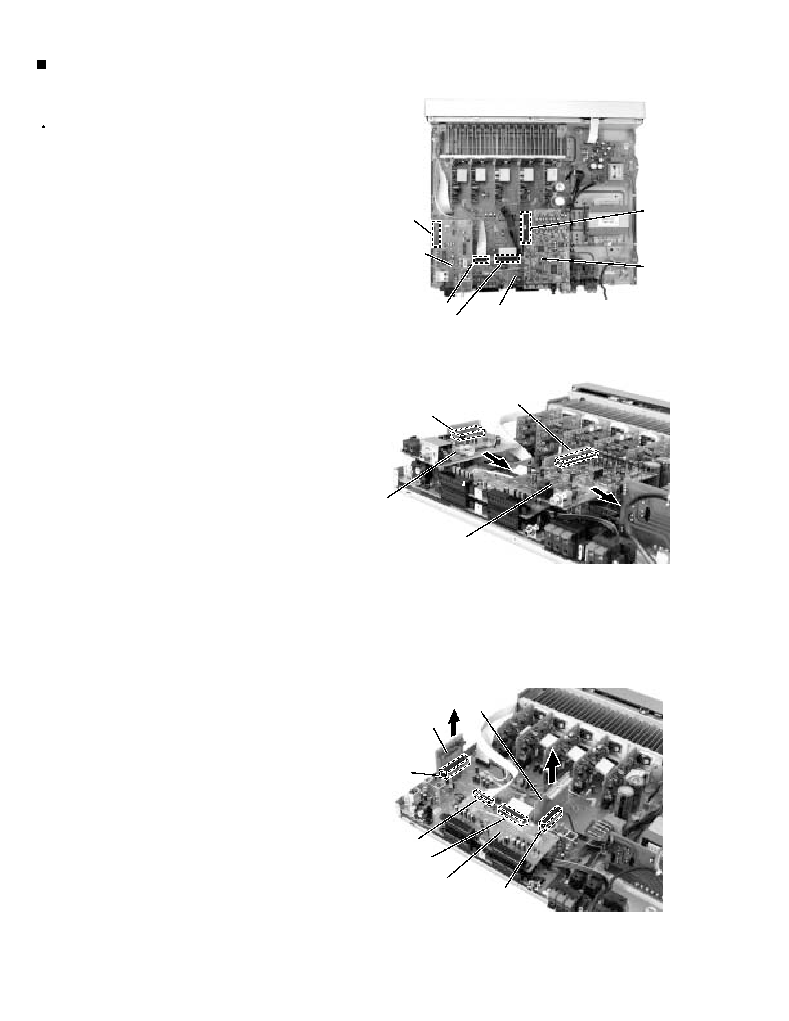
Prior to performing the following procedure, remove
the top cover and the rear panel.
Cut off the tie band fixing the harness.
Disconnect the tuner board and DSP board from
connector CN111,CN112 and CN681 on the each
Relay board.
Disconnect the Relay board from connector CN503,
CN504 and CN501 on the audio board.
Disconnect the card wire connected to connector
CN412 and CN512 on the Input board.
1.
2.
3.
4.
Removing each board connected to the
rear side of the audio board
(See Fig.5 to 7)
Fig.5
Fig.6
Fig.7
DSP
board
Input
board
Tuner
board
DSP board
CN111
CN111
CN112
CN681
CN512
CN503
CN504
CN412
CN512
Relay
board
CN412
CN501
Relay
board
Tuner
board
CN681
CN112
Input
board
RX-E100RSL/RX-E100RSB
1-5
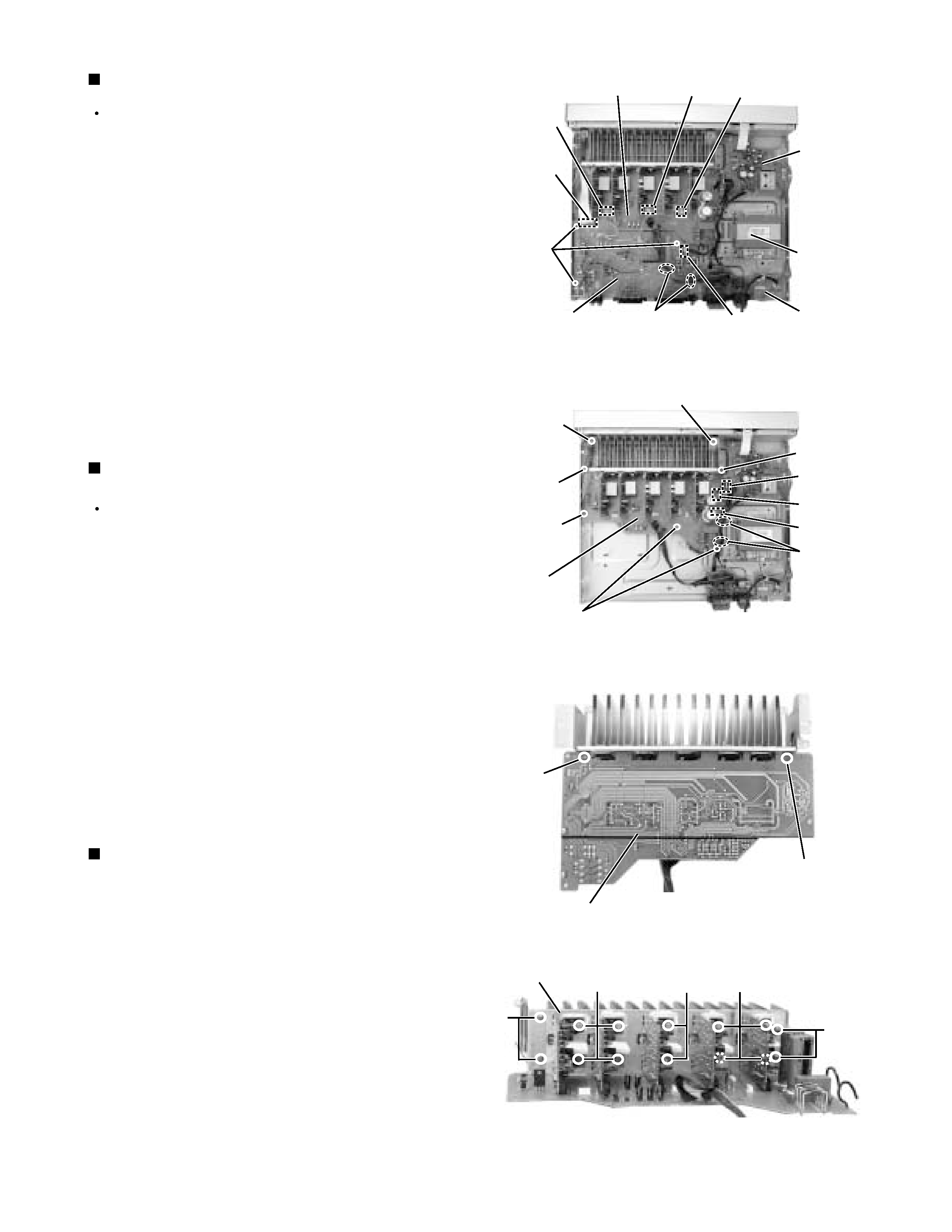
Prior to performing the following procedure, remove
the top cover , the rear panel and the each board.
Removing the audio board
(See Fig.8)
Disconnect the card wire from connector CN411 on
the audio board.
Disconnect the harness from connector CN205 on the
audio board.
Disconnect the harness from connector CN515,
CN516, and CN517on the main board.
Remove the harness band fixing the harness.
Remove the three screws G
attaching the audio
board assembly.
1.
2.
3.
4.
5.
Remove the ten screws K and four screws L
attaching the heat sink.
Remove the two screws J attaching the heat sink
from the rear side of main board.
1.
2.
Removing the Heat sink
(See Fig.10 to 11)
Prior to performing the following procedure, remove
the top cover, the rear panel and audio board.
Remove the harness band fixing the harness.
Disconnect the harness from connector CN707 on
the power supply board .
Disconnect the harness from connector CN202 and
CN206 on the main board .
Remove the five screws H and the two screws I
attaching the main board.
1.
2.
3.
4.
Removing the main board
(See Fig.9)
Fig.8
Fig.9
Fig.11
Fig.10
power
supply
board
Power / Fuse
board
CN411
Audio
board
Main board
rear side
Main
board
Heat sink
CN206
CN205
G
CN516
Power
transformer
CN707
H
H
H
H
I
I
L
L
K
K
K
J
J
CN515
CN517
CN202
Harness
band
Harness
band
Main board